ENGINE PERFORMANCE
3.5L
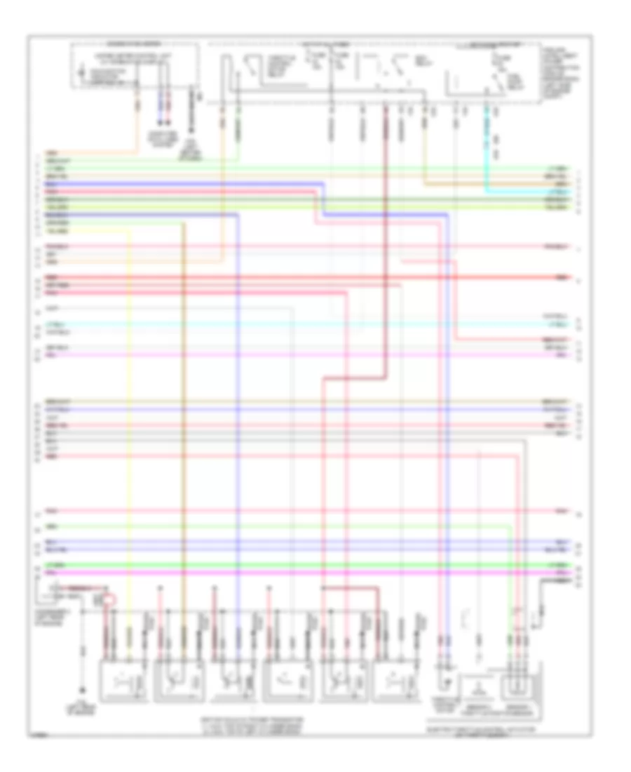
3.5L, Engine Performance Wiring Diagram (1 of 4) for Nissan Maxima SV 2012

List of elements for 3.5L, Engine Performance Wiring Diagram (1 of 4) for Nissan Maxima SV 2012:
- (1, 3 & 5: top of right cylinder bank) (2, 4 & 6: top of left cylinder bank) fuel injectors
- 12m
- Af+1
- Af+2
- Af-1
- Af-2
- Afh1
- Afh2
- Avcc1
- Avcc1-cursen,int
- Avcc1-pspres
- Avcc1-tps-b1
- Avcc2
- Battery current sensor
- Cursen
- E18
- E44
- E46
- E9 (left rear of engine compt)
- Ecm (engine control module) (left front of engine compt)
- Electronic controlled engine mount control solenoid valve
- Emmnv
- Engine coolant temperature sensor (left rear of engine)
- Engine oil temperature sensor (lower right front of engine)
- Enmn1
- Evap
- Evap canister purge volume control solenoid valve (top rear of engine)
- F13
- F14
- F2 e11
- Fpr
- Fuse 10a
- Fuse block (j/b) (lower left side of dash)
- Gnd
- Gnda-cursen,int
- Gnda-o2sr1, o2sr2
- Gnda-pdpres
- Gnda-pspres
- Gnda-tps-b1
- Gnda-tw,to1
- Hot in on or start
- Ign 1
- Ign 2
- Ign 3
- Ign 4
- Ign 5
- Ign 6
- Inj 1
- Inj 2
- Inj 3
- Inj 4
- Inj 5
- Inj 6
- Ipdm e/r (intelligent power distribution e201
- Junction block e44 & e46
- Module engine room) (left side of engine compt)
- Motor1-b1
- Motor2-b2
- Motrly-b1
- O2hr1
- O2hr2
- O2sr1
- O2sr2
- Output
- Pdpres
- Pnk
- Power steering pressure sensor (on power steering high pressure tube)
- Pspres
- Pwr
- Qa1-gnda-ta1
- Red
- Refrigerant pressure sensor (on a/c liquid tank)
- Sig
- Ssoff
- Ta1
- To1
- Tps1-b1
- Tps2-b1
- Vias 1
- Vias 2
- Vmot-b1
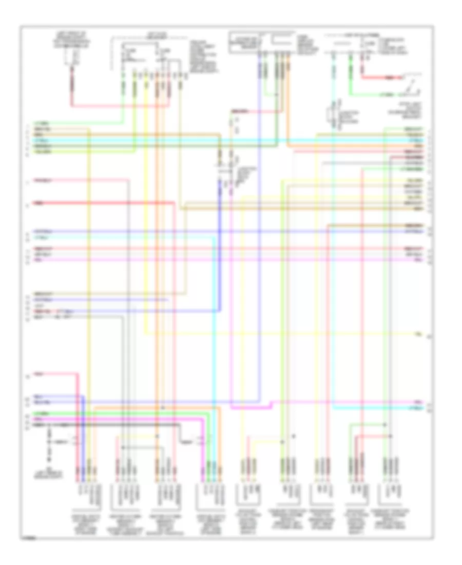
3.5L, Engine Performance Wiring Diagram (2 of 4) for Nissan Maxima SV 2012
List of elements for 3.5L, Engine Performance Wiring Diagram (2 of 4) for Nissan Maxima SV 2012:
- Combination meter
- Computer data lines system
- Condenser 2 (left rear of engine)
- E18
- E29 b10
- Ecm relay
- Electric throttle control actuator (on throttle body)
- F10
- F16 (left rear of engine)
- Fuel pump relay
- Fuse 15a
- Hot at all times
- Hot in on or start
- Ignition coils (w/ power transistor) (1, 3 & 5: top of right cylinder bank) (2, 4 & 6: top of left cylinder bank)
- Ipdm e/r (intelligent power distribution module engine room) (left side of engine compt)
- Loop wire
- M24
- M79 (left center of dash)
- Malfunction indicator lamp (mil)
- Nca
- Plug spark
- Pnk
- Red
- Sensor 1
- Sensor 2
- Spark plug
- Throttle control motor
- Throttle control motor relay
- Throttle positon sensor
- Unified meter control unit (w/ information display)
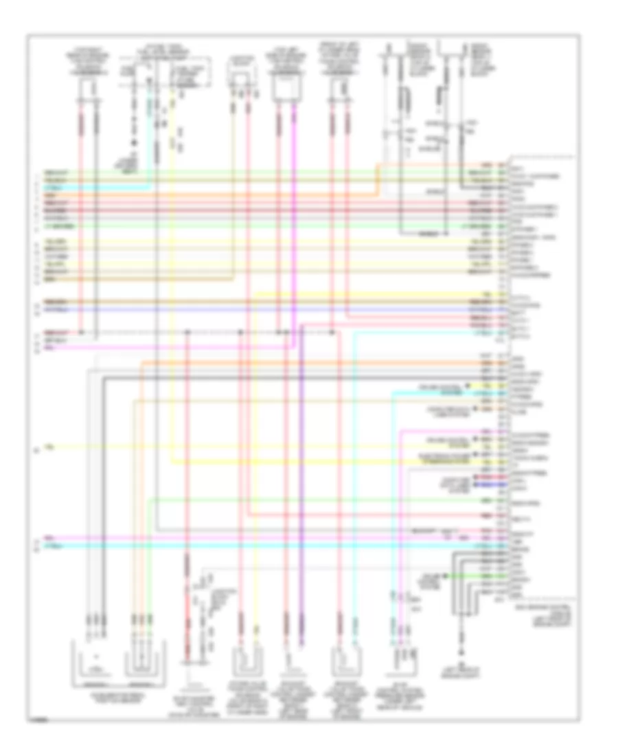
3.5L, Engine Performance Wiring Diagram (3 of 4) for Nissan Maxima SV 2012
List of elements for 3.5L, Engine Performance Wiring Diagram (3 of 4) for Nissan Maxima SV 2012:
- (left front of engine compt) tcm (transmission control module)
- Af (+)
- Af (-)
- Air/fuel ratio (a/f) sensor 1 (bank 1) (right side of engine)
- Air/fuel ratio (a/f) sensor 1 (bank 2) (left side of engine)
- Avcc1
- Avcc2
- Camshaft position sensor (phase) (bank 1) (rear of right cylinder head)
- Camshaft position sensor (phase) (bank 2) (rear of left cylinder head)
- Crankshaft position sensor (pos) (left rear of engine)
- E11
- E18
- E44
- E44 junction block e44 & e45 e45
- E45
- E9 (left rear of engine compt)
- Exhaust valve timing control position sensor (bank 1)
- Exhaust valve timing control position sensor (bank 2)
- F10
- Fuse 10a
- Fuse 15a
- Fuse block (j/b) (lower left side of dash)
- Gnd
- Heated oxygen sensor 2 (bank 1) (on right exhaust tube assembly)
- Heated oxygen sensor 2 (bank 2) (on left exhaust manifold)
- Heater (+)
- Heater (-)
- Hot at all times
- Hot in on or start
- Intake air temperature sensor
- Ipdm e/r (intelligent power distribution module engine room) (left side of engine compt)
- Junction block e44 & e45
- Mass airflow sensor (on intake air duct)
- Nca
- Output
- Phase
- Pnk
- Pos
- Pwr
- Red
- Sens (+)
- Sens (-)
- St rly
- Stop light switch (on brake pedal bracket)
3.5L, Engine Performance Wiring Diagram (4 of 4) for Nissan Maxima SV 2012
List of elements for 3.5L, Engine Performance Wiring Diagram (4 of 4) for Nissan Maxima SV 2012:
- (front of left cylinder head) intake valve timing control solenoid valve (bank 1)
- (in fuel tank) fuel level sensor unit & fuel pump
- (top left side of engine) vias control solenoid valve (bank 1)
- (top right rear of engine) vias control solenoid valve (bank 2)
- 30j
- 63g
- Accelerator pedal position sensor
- Aps1
- Aps2
- Ascdsw
- Avcc & e phase 1
- Avcc & e phase 2
- Avcc 1 & e phase1
- Avcc1-aps1
- Avcc2-aps2
- Avcc2-ftpres
- Avcc2-pdpres
- Avcc2-pos
- B10
- B42
- B7 (under driver's seat)
- Batt
- Bncsw
- Brake
- Can-h
- Can-l
- Cdcv
- Computer data lines system
- Cruise control system
- Cvtc 1
- Cvtc 2
- E phase 1
- E-phase 2
- E10
- E11
- E29
- E30
- E45
- E50
- E9 (left rear of engine compt)
- Ecm (engine control module) (left front of engine compt)
- Electronic power steering system
- Evap canister vent control valve (on evap canister)
- Evap control system pressure sensor (under left
- Evtc 1
- Evtc 2
- Exhaust valve timing control magnet retarder (bank 1) (left rear of engine)
- Exhaust valve timing control magnet retarder (bank 2) (left front of engine)
- F13
- F201
- F69
- Ftpres
- Fuel pump
- Fuel tank temper- ature sensor
- Gnd
- Gnd-pos
- Gnda-aps1
- Gnda-aps2
- Gnda-ascdsw
- Gnda-ftpres
- Gnda-knk1, knk2
- Gnda-tf
- Ignsw
- Intake valve timing control solenoid valve (bank 2) (front of right cylinder head)
- Junction block
- Junction block e44 & e45 e44
- Kline
- Knk
- Knk1
- Knk2
- Knock sensor (bank 1) (top of cylinder block)
- Knock sensor (bank 2) (top of cylinder block)
- Neut-h
- Phase 1
- Phase 2
- Pnk
- Pos
- Ptpres
- Pwr
- Qa1+
- Rear of vehicle)
- Red
- Sensor 1
- Sensor 2
- Shield
- Tacho (cabin)
- Vbr