ENGINE PERFORMANCE
3.5L
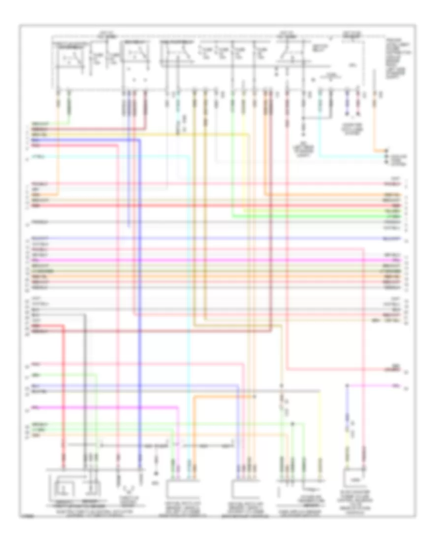
3.5L, Engine Performance Wiring Diagram (1 of 4) for Nissan Murano CrossCabriolet 2012

List of elements for 3.5L, Engine Performance Wiring Diagram (1 of 4) for Nissan Murano CrossCabriolet 2012:
- (front of engine) f83
- (front of engine) f84
- (ignition coils 1, 3 & 5: top of right cylinder bank) (ignition coils 2, 4 & 6: top of left cylinder bank) ignition coils (w/ power transistor)
- A/f+1
- A/f+2
- A/f-1
- A/f-2
- A/fh1
- A/fh2
- Avcc1-cur,intp
- Avcc1-pspres
- Avcc1-tps-b1
- Battery current sensor (near battery)
- Can-h
- Can-l
- Computer data lines system
- Condenser (f13)
- Cursen
- E10
- E346
- E38
- Emmnv
- Engine control module (ecm) (left side of engine compt)
- Engine coolant temperature sensor (left rear of engine)
- Engine oil temp sr
- Engine oil temperature sensor
- Evap
- F121 e7
- F123
- Fpr
- Gnd
- Gnda-curs,inpt
- Gnda-o2sr1,o2sr2
- Gnda-pspres
- Gnda-tps-b1
- Gnda-tw,to1
- Ign 1
- Ign 2
- Ign 3
- Ign 4
- Ign 5
- Ign 6
- Inj 1
- Inj 2
- Inj 3
- Inj 4
- Inj 5
- Inj 6
- Intake air temp sr
- Ipdm e/r (intelligent power distribution module engine room) (left side of engine compt)
- Mass a/f sensor
- Motor1-b1
- Motor2-b1
- Motrly-b1
- Nca
- O2hr1
- O2hr2
- O2sr1
- O2sr2
- Pdpres
- Plug spark
- Pnk
- Power steering pressure sensor
- Pspres
- Qa-gnda-ta1
- Red
- Refrigerant pressure sensor (left front of engine compt)
- Sensor gnd
- Spark plug
- Ssoff
- St rly
- Tcm (transmission control module) (on transmission)
- Temp sr
- Tps1-b1
- Tps2-b1
- Vias1
- Vias2
- Vmot1-b1
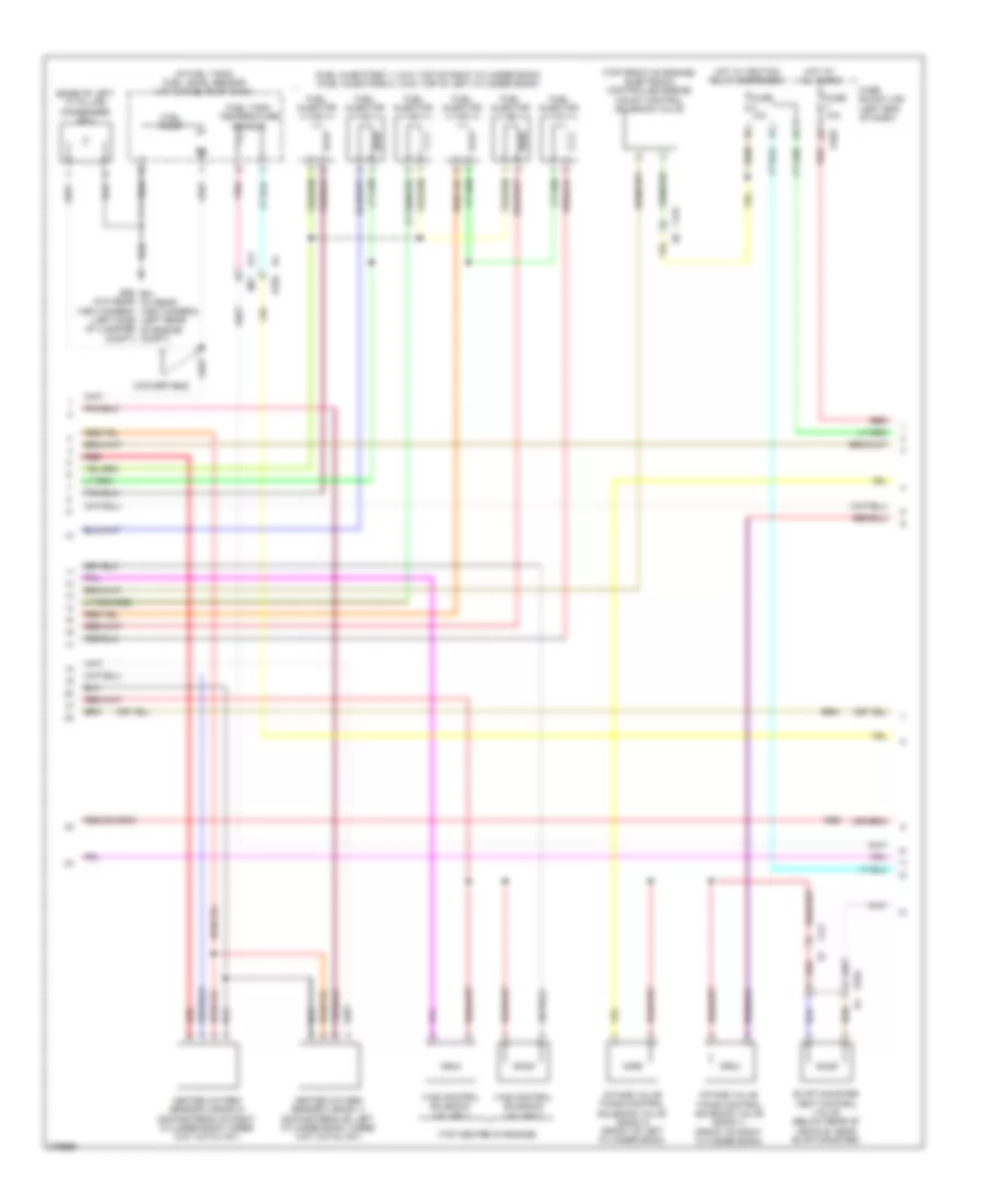
3.5L, Engine Performance Wiring Diagram (2 of 4) for Nissan Murano CrossCabriolet 2012
List of elements for 3.5L, Engine Performance Wiring Diagram (2 of 4) for Nissan Murano CrossCabriolet 2012:
- Air fuel ratio (a/f) sensor 1 (bank 1) (on right cylinder bank exhaust manifold)
- Air fuel ratio (a/f) sensor 1 (bank 2) (on left cylinder bank exhaust manifold)
- Close
- Computer data lines system
- Cooling fans system
- Cpu
- E10
- E104 b4
- E11
- E21 (left rear of engine compt)
- E38
- Ecm relay
- Electric throttle control actuator (integral to throttle body)
- Evap canister purge volume control solenoid valve (rear of intake manifold)
- F12
- F121
- Fuel pump relay
- Fuse 10a
- Fuse 15a
- Hot at all times
- Hot in on or start
- Ignition relay
- Intake air temperature sensor
- Ipdm e/r (intelligent power distribution module engine room) (left side of engine compt)
- Mass airflow sensor (on intake air duct)
- Nca
- Open
- Pnk
- Red
- Sensor 1
- Sensor 2
- Throttle control motor
- Throttle control motor relay
- Throttle position sensor
3.5L, Engine Performance Wiring Diagram (3 of 4) for Nissan Murano CrossCabriolet 2012
List of elements for 3.5L, Engine Performance Wiring Diagram (3 of 4) for Nissan Murano CrossCabriolet 2012:
- (base of left "c" pillar) condenser (b81)
- (fuel injectors 1, 3 & 5: top of right cylinder bank) (fuel injectors 2, 4 & 6: top of left cylinder bank)
- (in fuel tank) fuel level sensor unit & fuel pump (main)
- (top center of engine)
- (top front of engine) electronic controlled engine mount control solenoid valve
- (w/o rear view camera) (left side of luggage compt)
- B11
- B26 e21 (w/ rear view camera) (left rear of engine compt)
- Convertible
- E103
- E104
- Evap canister vent control valve (below rear of vehicle, near evap canister)
- F121
- F123 e6
- Fuel injector
- Fuel pump
- Fuel tank temperature sensor
- Fuse 10a
- Fuse block (j/b) (left end of dash)
- Heated oxygen sensor 2 (bank 1) (downstream of left cylinder bank three way catalyst)
- Heated oxygen sensor 2 (bank 2) (downstream of right cylinder bank three way catalyst)
- Hot at all times
- Hot w/ ignition relay energized
- Intake valve timing control solenoid valve (bank 1) (front of right cylinder bank)
- Intake valve timing control solenoid valve (bank 2) (front of left cylinder bank)
- M77
- Pnk
- Red
- Vias control solenoid valves 1
- Vias control solenoid valves 2
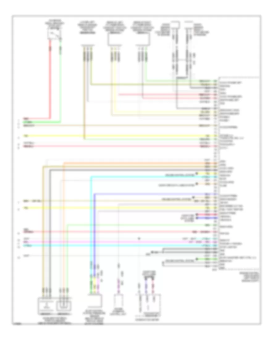
3.5L, Engine Performance Wiring Diagram (4 of 4) for Nissan Murano CrossCabriolet 2012
List of elements for 3.5L, Engine Performance Wiring Diagram (4 of 4) for Nissan Murano CrossCabriolet 2012:
- (lower left rear of engine) crankshaft position sensor (pos)
- (on brake pedal bracket) stoplight switch
- (rear of left cylinder bank) camshaft position sensor (phase) (bank 2)
- (rear of right cylinder bank) camshaft position sensor (phase) (bank 1)
- Accelerator pedal position sensor (above accelerator pedal)
- Aps1
- Aps2
- Ascd sw
- Avcc1-aps1
- Avcc1-phase1,ep1
- Avcc1-phase2,ep2
- Avcc2-aps2
- Avcc2-ftpres
- Avcc2-pdpres
- Avcc2-pos
- Break sw
- Can-h
- Can-l
- Combination meter
- Computer data lines system
- Cruise control system
- Cvtc 1
- E104
- E105
- E16
- E38
- Eng speed out sig
- Engine control module (ecm) (left side of engine compt)
- Evap
- Evap canister vent ctrl vlv
- Evap control system pressure sensor (below rear of vehicle, near evap canister)
- F200 f78
- Fuel lvl sens
- Fuel tank temp sr
- Gnd
- Gnd-phase1,ep1
- Gnd-phase2,ep2
- Gnd-pos
- Gnda-aps1
- Gnda-aps2
- Gnda-ascdsw
- Gnda-ftpres
- Gnda-knk1,knk2
- Gnda-tf
- Ign sw
- Intake vlv timing ctrl sol vlv
- Kline
- Knk1
- Knk2
- Knock sensor (bank 1) (top center of engine)
- Knock sensor (bank 2) (top center
- M11
- Malfunction indicator
- Phase 1
- Phase 2
- Pnk
- Pnp sig
- Pos
- Power steering control unit
- Pwr sply for ecm
- Red
- Sensor 1
- Sensor 2
- Sheild
- Shield
- Stop lamp sw
- Vehcan-h
- Vehcan-l