ENGINE PERFORMANCE
3.5L
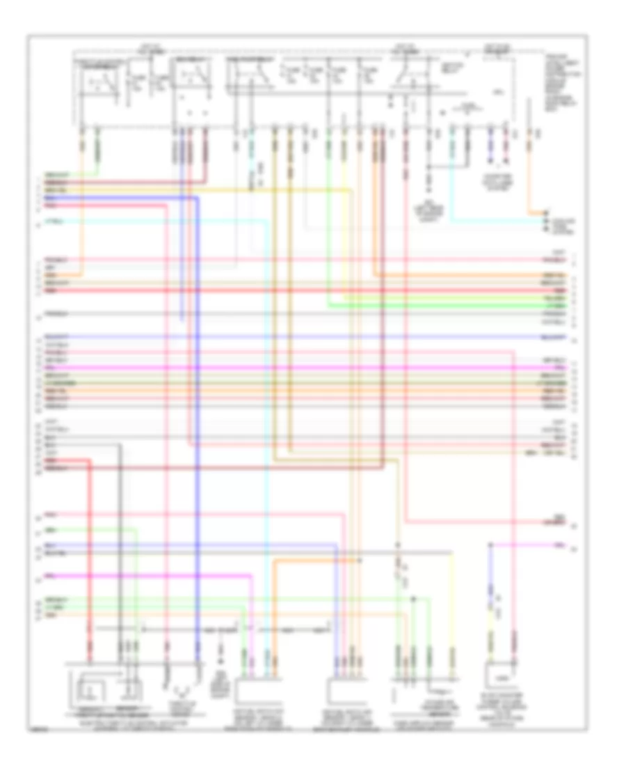
3.5L, Engine Performance Wiring Diagram (1 of 4) for Nissan Murano S 2013

List of elements for 3.5L, Engine Performance Wiring Diagram (1 of 4) for Nissan Murano S 2013:
- (front of engine) f83
- (front of engine) f84
- (ignition coils 1, 3 & 5: top of right cylinder bank) (ignition coils 2, 4 & 6: top of left cylinder bank) ignition coils (w/ power transistor)
- (top left rear of engine) condenser (f13)
- A/f sens 1 (b1)
- A/f sens 1 (b2)
- Batt cur sens
- Battery current sensor (near battery)
- Can-h
- Can-l
- Computer data lines system
- E10
- E346
- E38 (left side of engine compt)
- Ecm (engine control module) (left front of engine compt)
- Ecm rly
- Emmnv
- Eng colt temp sens
- Eng oil temp sens
- Engine coolant temperature sensor (left rear of engine)
- Engine oil temperature sensor (lower right front of engine)
- Evap
- F121 e7
- F123
- Furl pmp rly
- Gnd
- Heatd o2 sens2 (b1)
- Heatd o2 sens2 (b2)
- Ign 1
- Ign 2
- Ign 3
- Ign 4
- Ign 5
- Ign 6
- Inj 1
- Inj 2
- Inj 3
- Inj 4
- Inj 5
- Inj 6
- Intake air temp sens
- Ipdm e/r (intelligent power distribution module engine room) (in engine room relay box)
- Mass a/f sens
- Nca
- Plug spark
- Pnk
- Power steering pressure sensor
- Pwr str press sens
- Red
- Refr press sens
- Refrigerant pressure sensor (left front of engine compt)
- Sens gnd
- Sens pwr sply
- Spark plug
- St rly
- Tcm (transmission control module) (on transmission)
- Thrl ctrl mtr clse
- Thrl ctrl mtr opn
- Thrl ctrl mtr pwr sply
- Thrl ctrl mtr rly
- Thrl pos sens 1
- Thrl pos sens 2
- Vias1
- Vias2
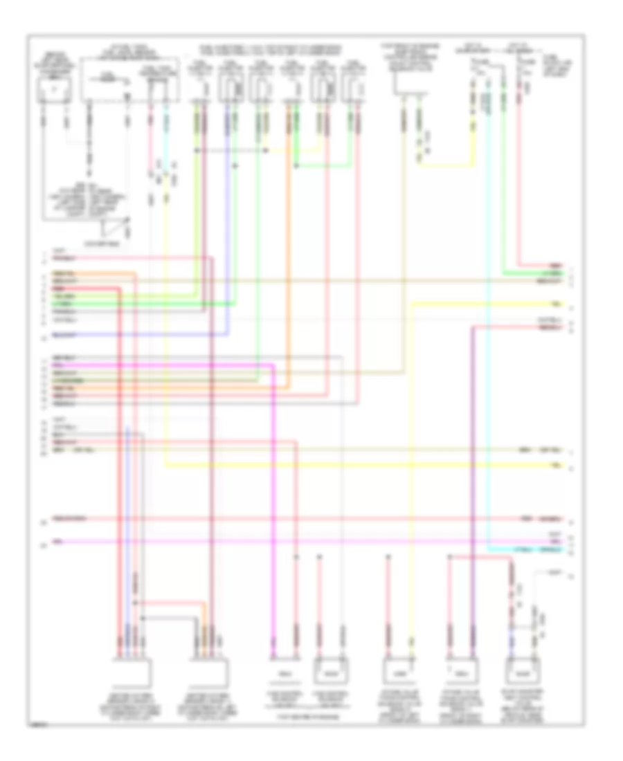
3.5L, Engine Performance Wiring Diagram (2 of 4) for Nissan Murano S 2013
List of elements for 3.5L, Engine Performance Wiring Diagram (2 of 4) for Nissan Murano S 2013:
- Air fuel ratio (a/f) sensor 1 (bank 1) (on right cylinder bank exhaust manifold)
- Air fuel ratio (a/f) sensor 1 (bank 2) (on left cylinder bank exhaust manifold)
- Close
- Computer data lines system
- Cooling fans system
- Cpu
- E10
- E104 b4
- E11
- E21 (left rear of engine compt)
- E38 (left side of engine compt)
- Ecm relay
- Electric throttle control actuator (integral to throttle body)
- Evap canister purge volume control solenoid valve (rear of intake manifold)
- F12
- F121
- Fuel pump relay
- Fuse 10a
- Fuse 15a
- Hot at all times
- Hot in on or start
- Ignition relay
- Intake air temperature sensor
- Ipdm e/r (intelligent power distribution module engine room) (in engine room relay box)
- Mass airflow sensor (on intake air duct)
- Nca
- Open
- Pnk
- Red
- Sensor 1
- Sensor 2
- Throttle control motor
- Throttle control motor relay
- Throttle position sensor
3.5L, Engine Performance Wiring Diagram (3 of 4) for Nissan Murano S 2013
List of elements for 3.5L, Engine Performance Wiring Diagram (3 of 4) for Nissan Murano S 2013:
- (behind left rear quarterpanel) condenser (b81)
- (fuel injectors 1, 3 & 5: top of right cylinder bank) (fuel injectors 2, 4 & 6: top of left cylinder bank)
- (in fuel tank) fuel level sensor unit & fuel pump (main)
- (top center of engine)
- (top front of engine) electronic controlled engine mount control solenoid valve
- (w/o rear view camera) (left side of luggage compt)
- B11
- B26 e21 (w/ rear view camera) (left rear of engine compt)
- Convertible
- E103
- E104
- Evap canister vent control valve (below rear of vehicle, near evap canister)
- F121
- F123 e6
- Fuel injector
- Fuel pump
- Fuel tank temperature sensor
- Fuse 10a
- Fuse block (j/b) (left end of dash)
- Heated oxygen sensor 2 (bank 1) (downstream of left cylinder bank three way catalyst)
- Heated oxygen sensor 2 (bank 2) (downstream of right cylinder bank three way catalyst)
- Hot at all times
- Hot in on or start
- Intake valve timing control solenoid valve (bank 1) (front of right cylinder bank)
- Intake valve timing control solenoid valve (bank 2) (front of left cylinder bank)
- M77
- Pnk
- Red
- Vias control solenoid valve 1
- Vias control solenoid valve 2
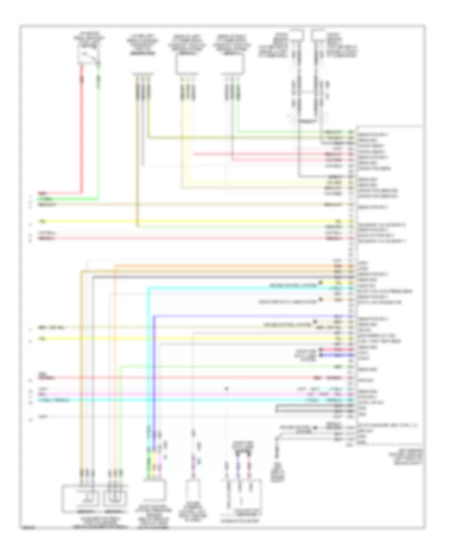
3.5L, Engine Performance Wiring Diagram (4 of 4) for Nissan Murano S 2013
List of elements for 3.5L, Engine Performance Wiring Diagram (4 of 4) for Nissan Murano S 2013:
- (lower left rear of engine) crankshaft position sensor (pos)
- (on brake pedal bracket) stop lamp switch
- (rear of left cylinder bank) camshaft position sensor (phase) (bank 2)
- (rear of right cylinder bank) camshaft position sensor (phase) (bank 1)
- Accelerator pedal position sensor (above accelerator pedal)
- Aps1
- Aps2
- Ascd sw
- Back-up pwr sply
- Brk sw
- Can-h
- Can-l
- Combination meter
- Computer data lines system
- Crank pos sens
- Crank pos sens (b1)
- Crank pos sens (b2)
- Cruise control system
- Cylinder bank)
- Data link connector
- E104
- E105
- E16
- E38 (left side of engine compt)
- Ecm (engine control module) (left front of engine compt)
- Eng speed out sig
- Evap canister vent ctrl vlv
- Evap control system pressure sensor (below rear of vehicle, near evap canister)
- Evap ctrl sys press sens
- F200 f78
- Fuel lvl sens
- Fuel tank temp sens
- Gnd
- Ign sw
- Knock sens 1
- Knock sens 2
- Knock sensor (bank 1) (top center of engine, in right cylinder bank)
- M11
- Malfunction indicator
- Pnk
- Pnp sig
- Power steering control unit (right center of dash)
- Pwr sply
- Red
- Sens gnd
- Sens pwr sply
- Sensor 1
- Sensor 2
- Sheild
- Shield
- Solenoid valve (bank 1)
- Solenoid valve (bank 2)
- Stop lmp sw