ENGINE PERFORMANCE
4.0L
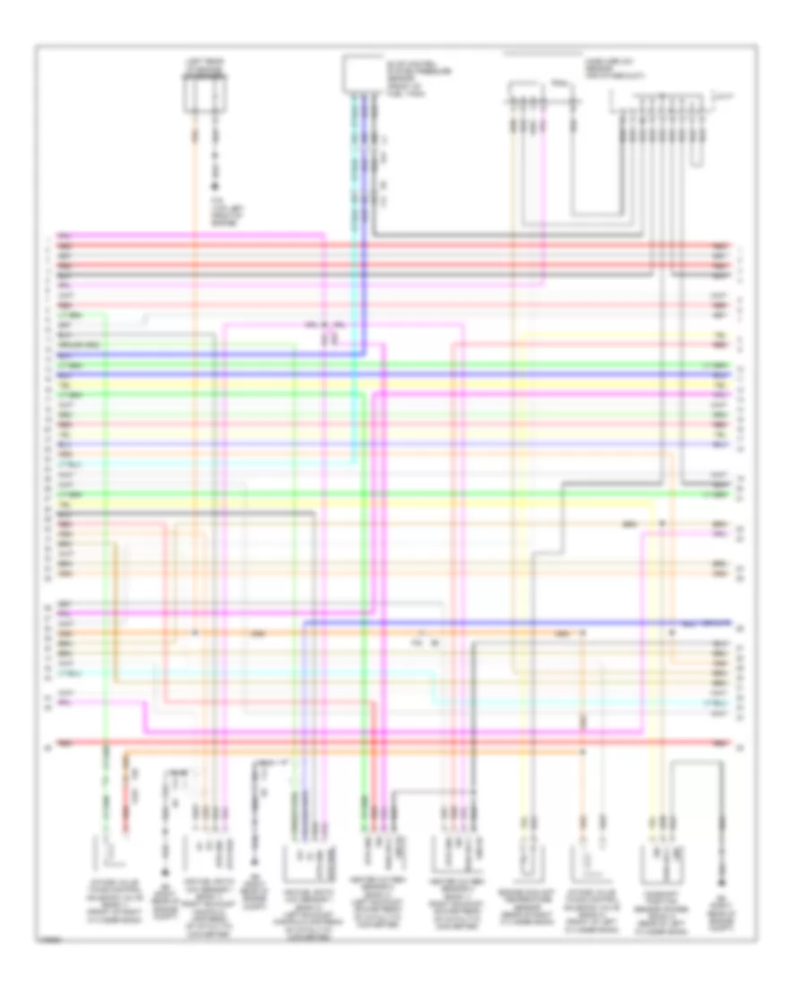
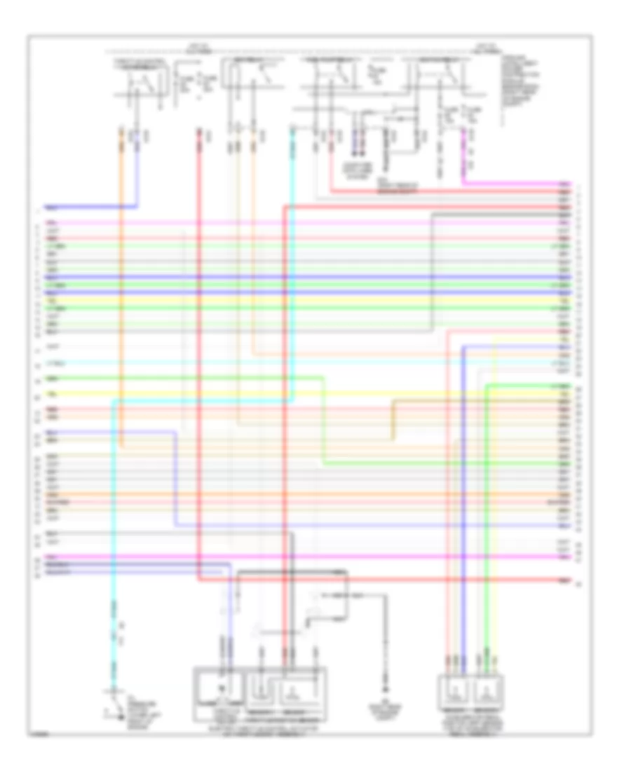
4.0L, Engine Performance Wiring Diagram (1 of 4) for Nissan NV3500 HD S 2012

List of elements for 4.0L, Engine Performance Wiring Diagram (1 of 4) for Nissan NV3500 HD S 2012:
- (right rear of engine compt)
- (top of left cylinder bank) fuel injectors
- (top of right cylinder bank) fuel injectors
- 17g
- Af+1
- Af+2
- Af-1
- Af-h1
- Af-h2
- Avcc
- Avcc (pdp)
- Avcc 2
- Camshaft position sensor (phase) (bank 1) (rear of right cylinder bank)
- Combination meter
- Computer data lines system
- Crankshaft position sensor (pos) (lower right rear of engine)
- Cvtcl
- Cvtcr
- E152
- E212
- E213
- E9 (right rear of engine compt)
- Ecm (right rear corner of engine compt)
- Evap
- Evap canister purge volume control solenoid valve (left side of engine)
- F14
- F201
- F204
- F204 f37
- F26
- F35 f202
- F37
- F54
- Ftprs
- Gnd
- Ignition coil 5 (w/ power transistor) (top of right cylinder bank)
- Inj 1
- Inj 2
- Inj 3
- Inj 4
- Inj 5
- Inj 6
- Knk 1
- Knk 2
- Knock sensor (bank 1) (top rear of right cylinder bank)
- Knock sensor (bank 2) (top rear of left cylinder bank)
- M23
- M24
- M31
- M61 (left side of dash)
- Malfunction indicator lamp
- Motor 1
- Motor 2
- Nca
- O2hrl
- O2hrr
- O2srl
- Oil pressure switch (lower left front of engine)
- Phase (lh)
- Phase (rh)
- Pnk
- Pos
- Pspres
- Pwr sply
- Pwr sup
- Qa+
- Red
- Refrigerant pressure sensor (left front of engine compt)
- Sig
- Spark plug
- Tps 1
- Unified meter control unit (w/ information display)
- Vias
- Vmot
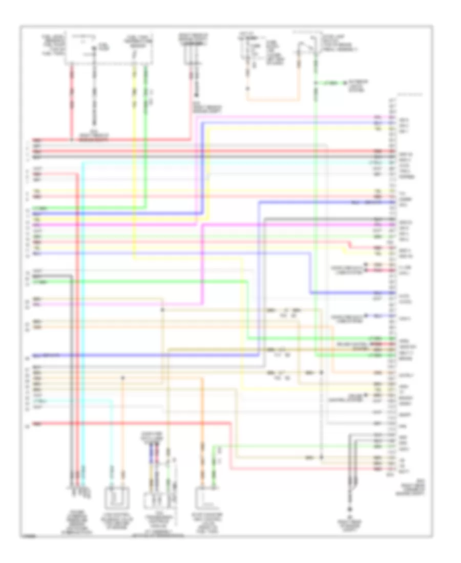
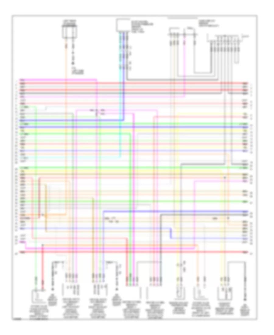
4.0L, Engine Performance Wiring Diagram (2 of 4) for Nissan NV3500 HD S 2012
List of elements for 4.0L, Engine Performance Wiring Diagram (2 of 4) for Nissan NV3500 HD S 2012:
- Accelerator pedal position (app) sensor (top of accelerator pedal assembly)
- Close
- Computer data lines system
- Cpu
- E119
- E121
- E122
- E124
- E15 (right rear of engine compt)
- E207
- E51
- E70
- E9 (right rear of engine compt)
- Ecm relay
- Electric throttle control actuator (on throttle body assembly)
- F16 (top left front of engine)
- F201
- F26
- F26 f201
- F32
- Fuel pump relay
- Fuse 10a
- Fuse 15a
- Fuse 20a
- Fuse block (j/b) (lower left end of dash)
- Hot at all times
- Hot in on or start
- Ignition coil 1 (w/ power transistor) (top of right cylinder bank)
- Ignition coil 2 (w/ power transistor) (top of left cylinder bank)
- Ignition coil 3 (w/ power transistor) (top of right cylinder bank)
- Ignition coil 4 (w/ power transistor) (top of left cylinder bank)
- Ignition coil 6 (w/ power transistor) (top of left cylinder bank)
- Ignition relay
- Ipdm e/r (intelligent power distribution module engine room) (right rear of engine compt)
- M39
- Nca
- Open
- Pnk
- Red
- Sensor 1
- Sensor 2
- Spark plug
- Throttle control motor
- Throttle control motor relay
- Throttle position sensor
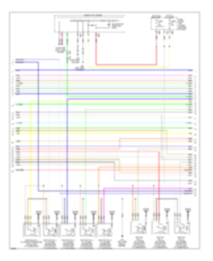
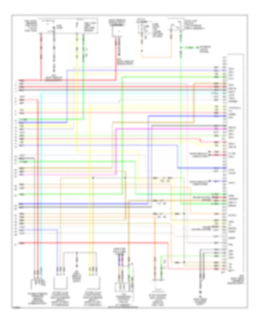
4.0L, Engine Performance Wiring Diagram (3 of 4) for Nissan NV3500 HD S 2012
List of elements for 4.0L, Engine Performance Wiring Diagram (3 of 4) for Nissan NV3500 HD S 2012:
- (left rear of engine) condenser 1
- 45c
- 46c
- 47c
- Af+
- Af-
- Air fuel ratio (a/f) sensor 1 (bank 1) (right exhaust manifold, upstream of catalytic converter)
- Air fuel ratio (a/f) sensor 1 (bank 2) (left exhaust manifold,upstream of catalytic converter)
- Camshaft position sensor (phase) (bank 2) (rear of left cylinder bank)
- E41
- E9 (right rear of engine compt)
- Engine coolant temperature sensor (rear of right cylinder bank)
- Evap control system pressure sensor (front of fuel tank)
- F14
- F16 (top left front of engine)
- F201
- F26
- F32
- Gnd
- Gnd 02
- Heated oxygen sensor 2 (bank 1) (right exhaust, downstream of catalytic converter)
- Heated oxygen sensor 2 (bank 2) (left exhaust, downstream of catalytic converter)
- Htr gnd
- Htr pwr
- Intake valve timing control solenoid valve (bank 1) (front of right cylinder bank)
- Intake valve timing control solenoid valve (bank 2) (front of left cylinder bank)
- J/c f1
- Mass airflow sensor (air intake duct)
- Pwr sply
- Red
- Sig
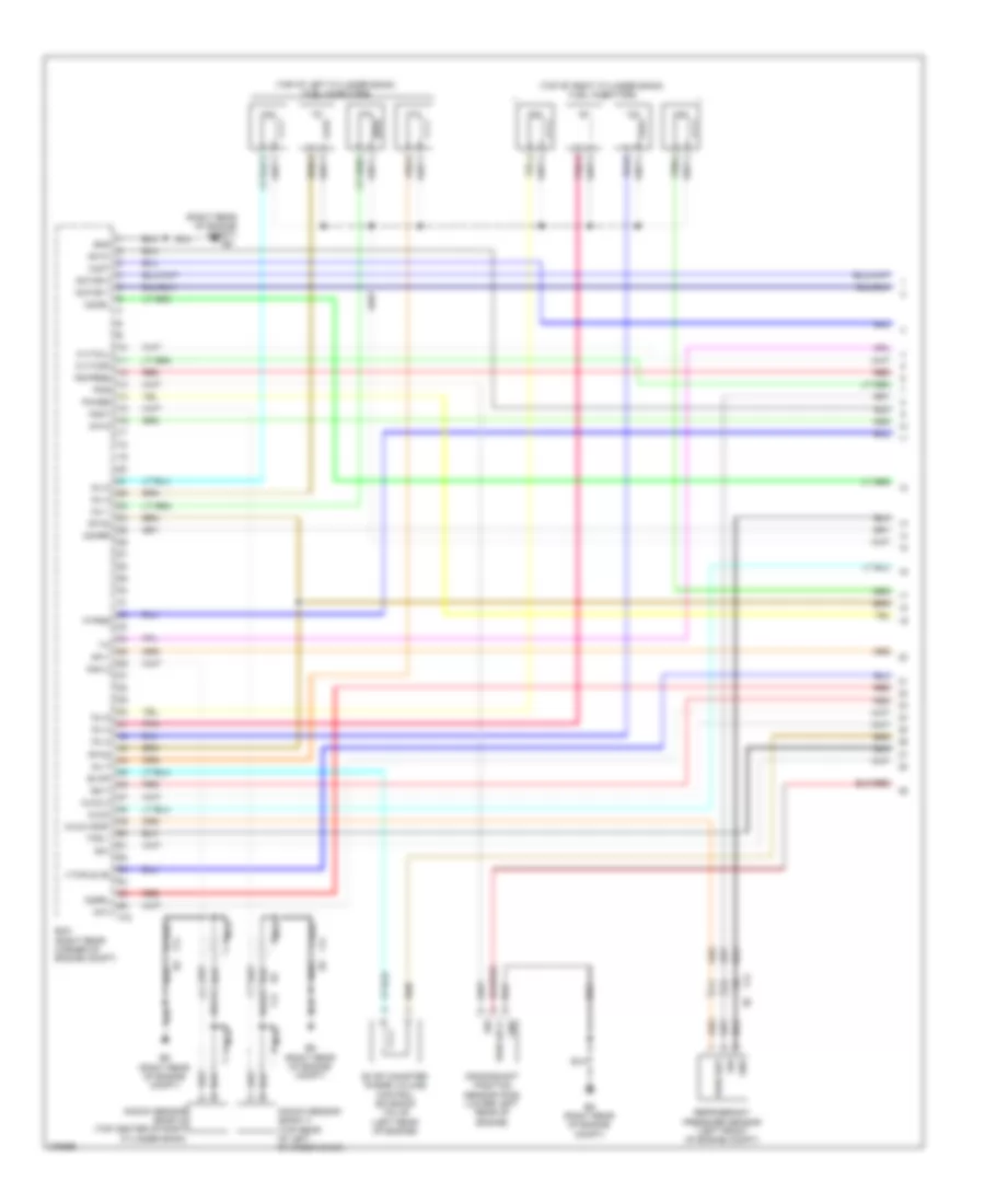
4.0L, Engine Performance Wiring Diagram (4 of 4) for Nissan NV3500 HD S 2012
List of elements for 4.0L, Engine Performance Wiring Diagram (4 of 4) for Nissan NV3500 HD S 2012:
- (right rear of engine compt) condenser 2
- 30c
- 31c
- 42c
- 44c
- 48c
- 52c
- A/t assembly (bottom of transmission)
- Af-2
- Aps1
- Aps2
- Ascd sw
- Avcc
- Avcc2
- Batt
- Bncsw
- Brake
- C1 e41
- Can h
- Can l
- Cdcv
- Computer data lines system
- Cruise control system
- E15 (right rear of engine compt)
- E16
- E41
- E51
- E9 (right rear of engine compt)
- Ecm (right rear corner of engine compt)
- Evap canister vent control valve (front of fuel tank)
- Exterior lights system
- F14
- F32
- F502 rly
- F54
- Fpr
- Fuel level sensor & fuel pump (top of fuel tank)
- Fuel pump
- Fuel tank temperature sensor
- Fuse 10a
- Fuse block (j/b) (lower left end of dash)
- Gnd
- Gnd 02
- Gnd a
- Gnd a2
- Hot at all times
- Ign 1
- Ign 2
- Ign 3
- Ign 4
- Ign 5
- Ign 6
- Ignsw
- K line
- Motrly
- Neut h
- O2srr
- Pdpres
- Pnk
- Power steering pressure sensor (on power steering pump)
- Pwr
- Red
- Sig
- Sply
- Ssoff
- Stop lamp switch (top of brake pedal assembly)
- Tcm (transmisson controle module)
- Tps 2
- Vias control solenoid valve (top center of engine)
5.6L
5.6L, Engine Performance Wiring Diagram (1 of 5) for Nissan NV3500 HD S 2012
List of elements for 5.6L, Engine Performance Wiring Diagram (1 of 5) for Nissan NV3500 HD S 2012:
- (right rear of engine compt)
- (top of left cylinder bank) fuel injectors
- (top of right cylinder bank) fuel injectors
- A/f+2
- A/f1
- Af+1
- Af-h1
- Af-h2
- Avcc
- Avcc (pdp)
- Avcc 2
- C-vtc(l)
- C-vtc(r)
- Crankshaft position sensor (pos) (lower left rear of engine)
- E9 (right rear of engine compt)
- Ecm (right rear corner of engine compt)
- Evap
- Evap canister purge volume control solenoid valve (left rear of engine)
- F14
- F72
- Ftprs
- Gnd
- Ign 7
- Inj 1
- Inj 2
- Inj 3
- Inj 4
- Inj 5
- Inj 6
- Inj 7
- Knk 2
- Knk1
- Knock sensor (bank 1) (top rear of left cylinder bank)
- Knock sensor (bank 2) (top center of right cylinder bank)
- Motor 1
- Motor 2
- Nca
- O2hrl
- O2hrr
- O2srl
- Phase
- Pnk
- Pos
- Ps-pres
- Pwr sply
- Pwr sup
- Qa+
- Red
- Refrigerant pressure sensor (left front of engine compt)
- Sig
- Tps 1
- Vmot
- Vtcpus (r)
5.6L, Engine Performance Wiring Diagram (2 of 5) for Nissan NV3500 HD S 2012
List of elements for 5.6L, Engine Performance Wiring Diagram (2 of 5) for Nissan NV3500 HD S 2012:
- 17g
- Combination meter
- Computer data lines system
- E152
- E51
- F16 (left side side of engine)
- Fuse 10a
- Fuse block (j/b) (lower left end of dash)
- Hot at all times
- Hot in on or start
- Ignition coil 1 (w/ power transistor) (top of left cylinder bank)
- Ignition coil 2 (w/ power transistor) (top of right cylinder bank)
- Ignition coil 3 (w/ power transistor) (top of left cylinder bank)
- Ignition coil 4 (w/ power transistor) (top of right cylinder bank)
- Ignition coil 5 (w/ power transistor) (top of left cylinder bank)
- Ignition coil 6 (w/ power transistor) (top of right cylinder bank)
- Ignition coil 7 (w/ power transistor) (top of left cylinder bank)
- Ignition coil 8 (w/ power transistor) (top of right cylinder bank)
- M23
- M24
- M31
- M39
- M57 (left end of dash)
- M61 (left side of dash)
- Malfunction indicator lamp
- Nca
- Pnk
- Red
- Spark plug
- Unified meter control unit (w/ information display)
5.6L, Engine Performance Wiring Diagram (3 of 5) for Nissan NV3500 HD S 2012
List of elements for 5.6L, Engine Performance Wiring Diagram (3 of 5) for Nissan NV3500 HD S 2012:
- Accelerator pedal position (app) sensor (top of accelerator pedal assembly)
- Close
- Computer data lines system
- Cpu
- E119
- E121
- E122
- E124
- E15 (right rear of engine compt)
- E9 (right rear of engine compt)
- Ecm relay
- Electric throttle control actuator (on throttle body assembly)
- F14
- F32
- Fuel pump relay
- Fuse 15a
- Fuse 20a
- Hot at all times
- Ignition relay
- Ipdm e/r (intelligent power distribution module engine room) (right rear of engine compt)
- Nca
- Oil pressure switch (lower left front of engine)
- Open
- Pnk
- Red
- Sensor 1
- Sensor 2
- Throttle control motor
- Throttle control motor relay
- Throttle position sensor
5.6L, Engine Performance Wiring Diagram (4 of 5) for Nissan NV3500 HD S 2012
List of elements for 5.6L, Engine Performance Wiring Diagram (4 of 5) for Nissan NV3500 HD S 2012:
- (left rear of engine) condenser 1
- 45c
- 46c
- 47c
- Af+
- Af-
- Air fuel ratio (a/f) sensor 1 (bank 1) (left exhaust manifold, upstream of catalytic converter)
- Air fuel ratio (a/f) sensor 1 (bank 2) (right exhaust manifold, upstream of catalytic converter)
- Camshaft position sensor (phase) (front of left cylinder bank)
- E41
- E9 (right rear of engine compt)
- Engine coolant temperature sensor (top front of engine)
- Evap control system pressure sensor (front of fuel tank)
- F14
- F16 (left side of engine)
- F203
- F32
- F36
- Gnd
- Heated oxygen sensor 2 (bank 1) (left exhaust, downstream of catalytic converter)
- Heated oxygen sensor 2 (bank 2) (right exhaust, downstream of catalytic converter)
- Htr gnd
- Htr pwr
- Intake valve timing control solenoid valve (bank 1) (front of left cylinder bank)
- Intake valve timing control solenoid valve (bank 2) (front of right cylinder bank)
- J/c f1
- Mass airflow sensor (air intake duct)
- Pwr sply
- Red
- Sig
5.6L, Engine Performance Wiring Diagram (5 of 5) for Nissan NV3500 HD S 2012
List of elements for 5.6L, Engine Performance Wiring Diagram (5 of 5) for Nissan NV3500 HD S 2012:
- (right rear of engine compt) condenser 2
- 30c
- 31c
- 42c
- 44c
- 48c
- 52c
- A/t assembly (bottom of transmission)
- Af-2
- Aps1
- Aps2
- Ascdsw
- Avcc
- Avcc2
- Batt
- Bncsw
- Brake
- C1 e41
- Can h
- Can l
- Cdcv
- Computer data lines system
- Cruise control system
- E15 (right rear of engine compt)
- E41
- E51
- E77
- E9 (right rear of engine compt)
- Ecm (right rear corner of engine compt)
- Evap canister vent control valve (front of fuel tank)
- Exterior lights system
- F14
- F32
- F502 rly
- F72
- Fpr
- Fuel level sensor & fuel pump (top of fuel tank)
- Fuel pump
- Fuel tank temp- erature sensor
- Fuse 10a
- Fuse block (j/b) (lower left end of dash)
- Gnd
- Gnd 02
- Gnd a
- Gnd a2
- Hot at all times
- Ign 1
- Ign 2
- Ign 3
- Ign 4
- Ign 5
- Ign 6
- Ign 8
- Ignsw
- Inj 8
- Intake valve timing control position sensor (bank 1) (front of left cylinder bank)
- Intake valve timing control position sensor (bank 2) (front of right cylinder bank)
- K line
- Motrly
- Neut h
- O2srr
- Pdpres
- Pnk
- Power steering pressure sensor (on power steering pump)
- Pwr
- Red
- Sig
- Sply
- Ssoff
- Stop lamp switch (top of brake pedal assembly)
- Tcm (transmisson controle module)
- Tps 2
- Vts pus (l)