ENGINE PERFORMANCE
2.5L
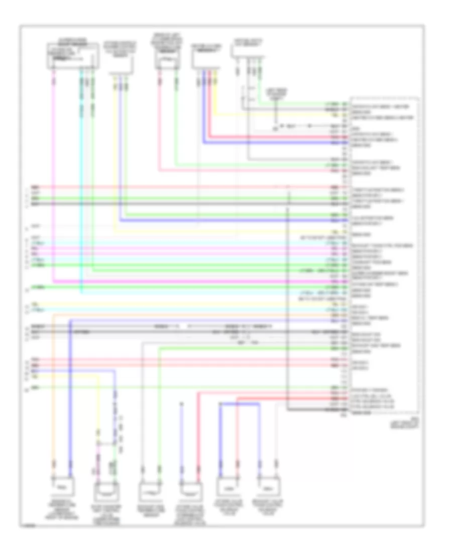
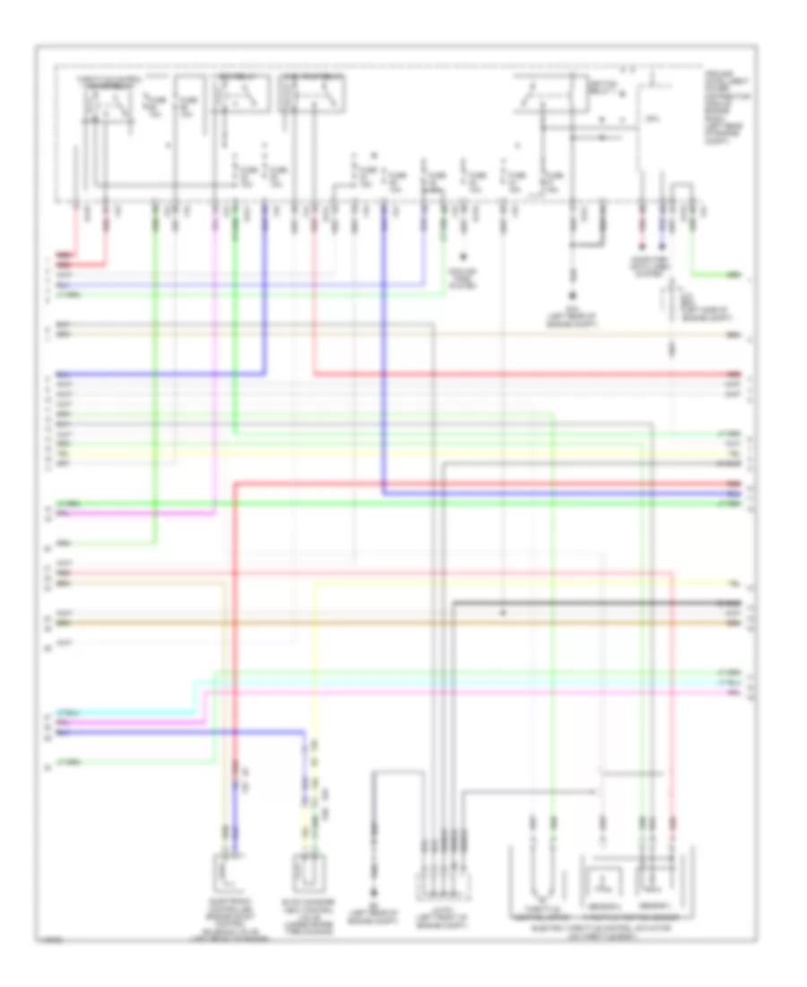
2.5L, Engine Controls Wiring Diagram (1 of 6) for Nissan Pathfinder S 2014

List of elements for 2.5L, Engine Controls Wiring Diagram (1 of 6) for Nissan Pathfinder S 2014:
- (left rear of engine compt) e9
- Canister ctrl solenoid valve
- Crankshaft position sensor (pos) (lower left rear of engine)
- E119
- E19 f33
- E58
- Ecm (left front of engine compt)
- Ecm rly (self shut-off)
- Eng oil press sens
- Engine oil pressure sensor (lower front of engine)
- F51
- Fuel inj 1
- Fuel inj 2
- Fuel inj 3
- Fuel inj 4
- Fuel pmp rly
- Fuel rail pressure sensor
- Fuel rly press sens
- Gnd
- Intake air air temp sens
- Intake air temperature sensor
- Intake manifold runner control valve
- Ipdm e/r (intelligent power distribution e218 module engine room) (left rear of engine compt)
- Knock sens
- Knock sensor
- Mass air flow sens
- Mass airflow sensor (on air cleaner box)
- Pnk
- Position sens
- Press sens
- Red
- Refrigerant pressure sensor (front left side of radiator)
- Sens gnd
- Sens pwr sply
- Sens sply
- Shield
- Supercharger bypass valve control motor relay (in fuse, fusible link & relay box 1)
- Temp sens
- Thr pos sens 1
- Thr pos sens 2
- Throttle ctrl mtr (close)
- Throttle ctrl mtr (open)
- Throttle ctrl mtr pwr sply
- Throttle ctrl mtr rly
- Valve (close)
- Valve (open)
- Valve ctrl mtr
- Valve ctrl mtr pwr sply
- Valve ctrl mtr rly
- Valve position sens 1
- Valve position sens 2
- Valve pwr sply
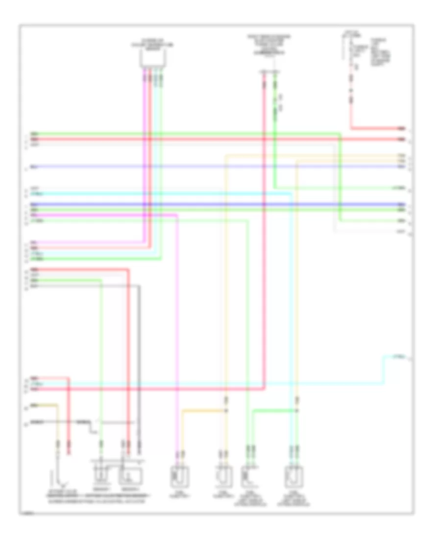
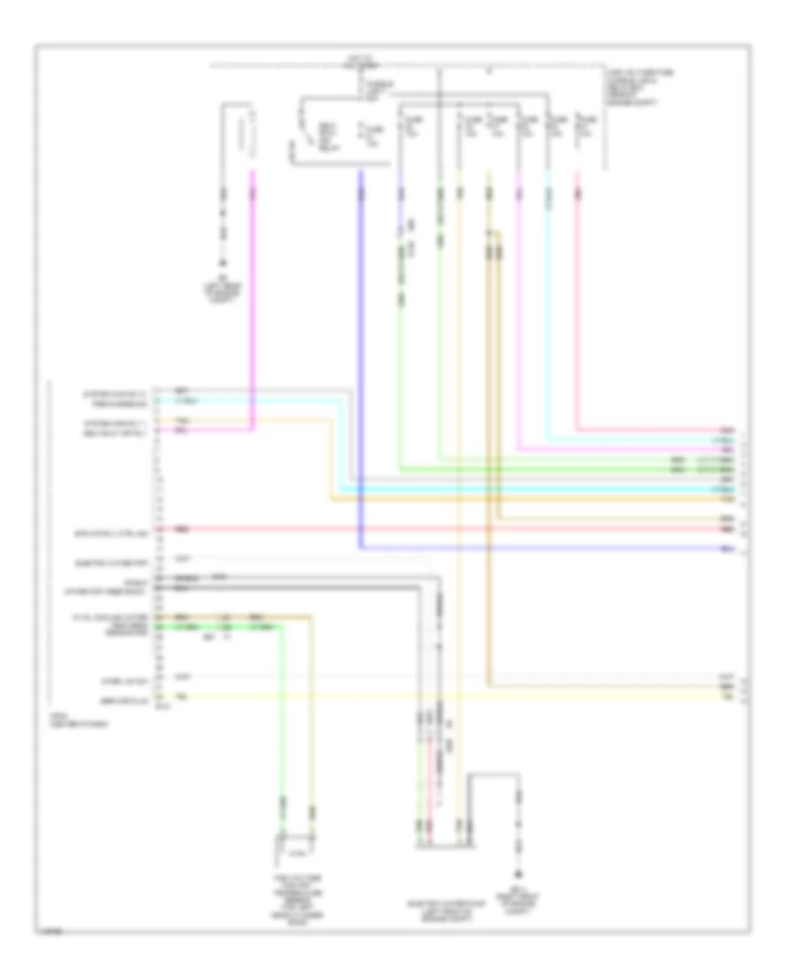
2.5L, Engine Controls Wiring Diagram (2 of 6) for Nissan Pathfinder S 2014
List of elements for 2.5L, Engine Controls Wiring Diagram (2 of 6) for Nissan Pathfinder S 2014:
- (right rear of engine) evap canister purge volume control solenoid valve
- Bypass valve control motor
- Bypass valve position sensor
- Charge air cooler temperature sensor
- E27
- F33 e19
- Fuel injector 1
- Fuel injector 2 (left side of intake manifold)
- Fuel injector 3
- Fuel injector 4 (left side of intake manifold)
- Fusible link box (battery) (left side of engine compt)
- Fusible link c 80a
- Hot at all times
- Pnk
- Red
- Sensor 1
- Sensor 2
- Shield
- Supercharger bypass valve control actuator
- Tan
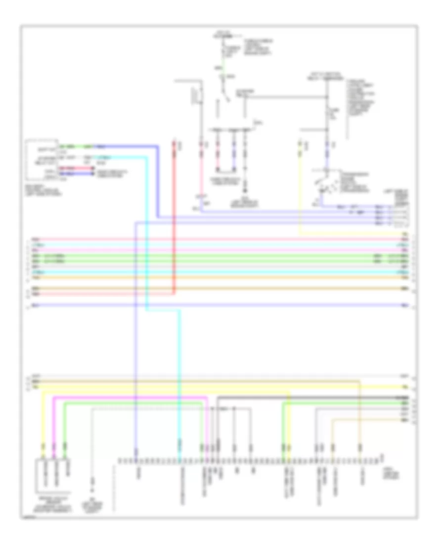
2.5L, Engine Controls Wiring Diagram (3 of 6) for Nissan Pathfinder S 2014
List of elements for 2.5L, Engine Controls Wiring Diagram (3 of 6) for Nissan Pathfinder S 2014:
- B40
- Brk pdl position sw
- Can-h
- Can-l
- Computer data lines system
- Cooling fans system
- Cpu
- E118
- E119
- E121
- E15 (left rear of engine compt)
- E16
- E34
- E9 (left rear of engine compt)
- Ecm (left front of engine compartment)
- Ecm relay
- Eng spd o/p sig
- Evap canister vent ctrl valve
- Evap control system pressure sensor (under spare tire housing)
- Evap ctrl system press sens
- F19
- F24
- Fuel pmp ctrl module
- Fuel pump relay
- Fuel tank press sens
- Fuse 10a
- Fuse 15a
- Gnd
- Hev can-h
- Hev can-l
- Ignition relay 1
- Ignition sw
- Ipdm e/r (intelligent power distribution module engine room) (left rear of engine compt)
- Pnk
- Pwr sply
- Red
- Sens gnd
- Sens pwr sply
- Sound systems
- Stp lmp sw
- Tan
- Throttle control motor relay
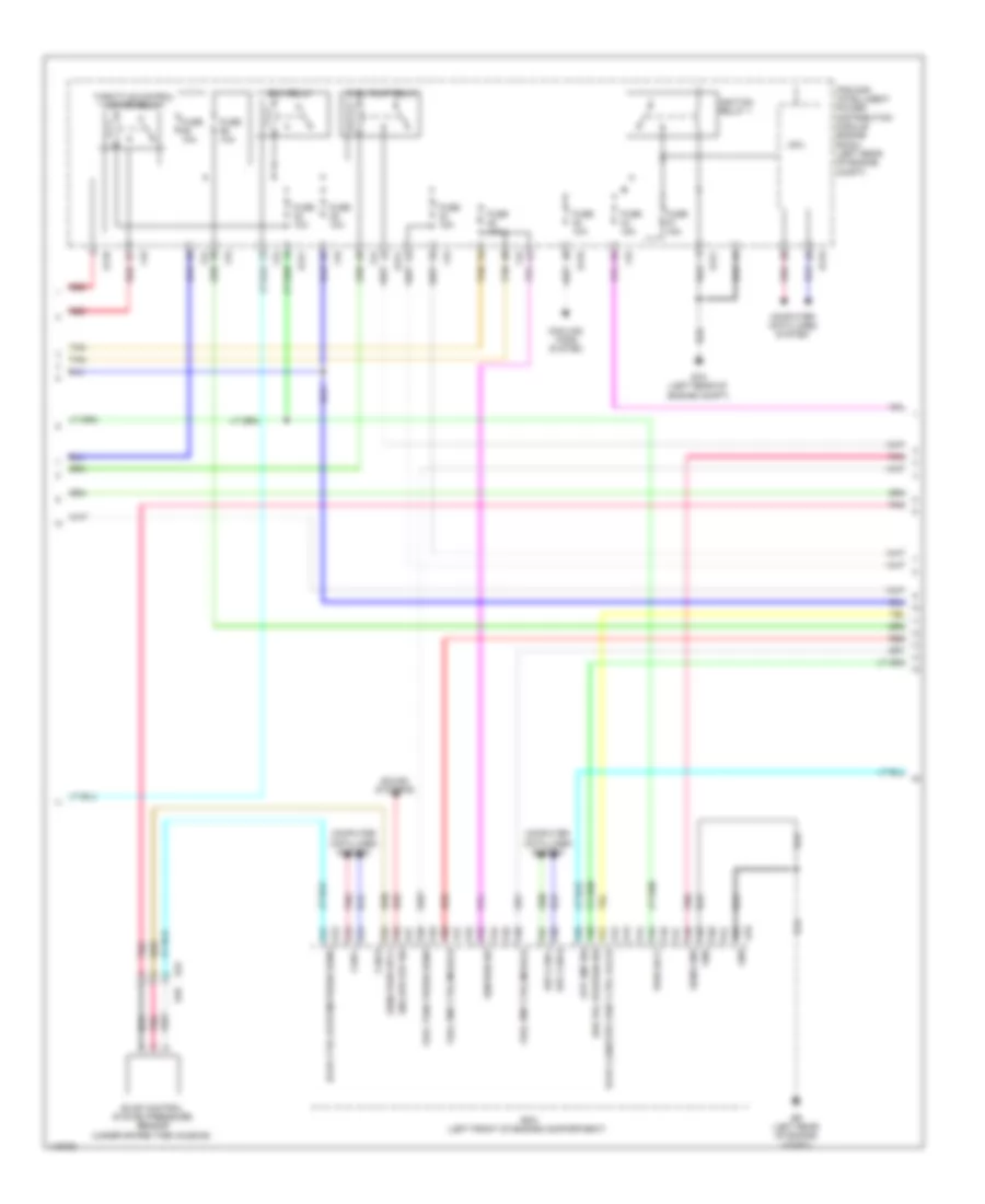
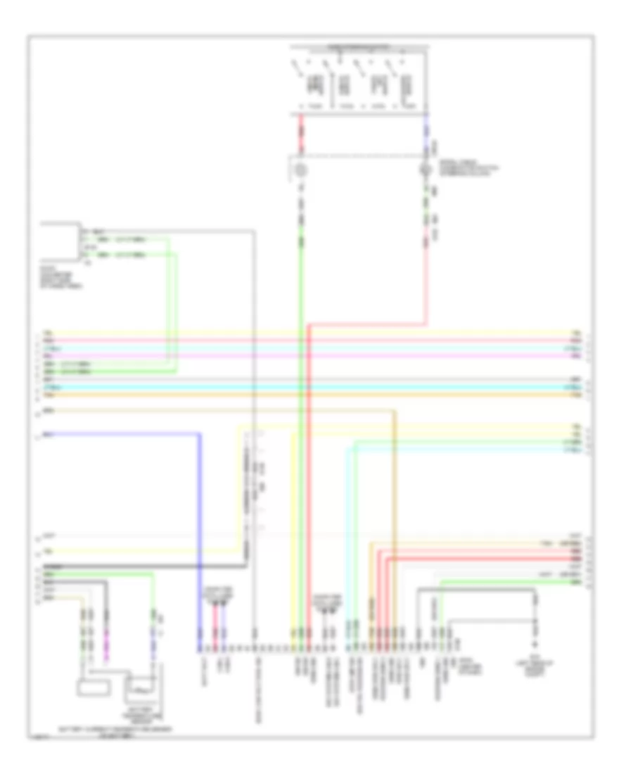
2.5L, Engine Controls Wiring Diagram (4 of 6) for Nissan Pathfinder S 2014
List of elements for 2.5L, Engine Controls Wiring Diagram (4 of 6) for Nissan Pathfinder S 2014:
- (in fuel tank) fuel level sensor unit & fuel pump
- (left "d" pillar) j/c b16
- (left rear of cargo area)
- 13p
- B19
- B40 e34
- B43 e33
- Bat
- Brake pedal position switch (top of brake pedal assembly)
- Brk pdl pos sw
- Can-h
- Can-l
- Combination meter
- Computer data lines system
- E130
- E28
- Fuel level sensor
- Fuel pump
- Fuel pump control module (fpcm)
- Fuel tank temperature sensor
- Fuse 10a
- Fuse 30 10a
- Fuse 5a
- Fuse block (j/b) (left end of dash)
- Gnd 1
- Gnd 2
- Hev can-h
- Hev can-l
- Hot at all times
- Hot w/ ignition relay 2 energized
- Hpcm
- Ign
- Instrument cluster system
- J/c e01 (left end of dash)
- J/c e22 (left end of dash)
- M24
- M57 (left side of dash)
- Malfunction indicator lamp (mil)
- Pnk
- Red
- Shield
- Stop lamp switch (top of brake pedal assembly)
- Tan
- Unified meter control unit (w/ information display)
2.5L, Engine Controls Wiring Diagram (5 of 6) for Nissan Pathfinder S 2014
List of elements for 2.5L, Engine Controls Wiring Diagram (5 of 6) for Nissan Pathfinder S 2014:
- (left rear of engine compt) e15
- (left rear of engine) condenser-1
- (on throttle body) electric throttle control actuator
- (or red)
- (top of left cylinder head) ignition coil 2 (w/ power transistor)
- (top of left cylinder head) ignition coil 4 (w/ power transistor)
- (top of right cylinder head) ignition coil 1 (w/ power transistor)
- (top of right cylinder head) ignition coil 3 (w/ power transistor)
- Camshaft position sensor
- E87
- Eng mount drive sig
- Eng mount ground
- Eng mount pwr sply 1
- Eng mount pwr sply 2
- Eng mount sig
- Engine mount control module
- Exhaust valve timing control position sensor
- F40
- F60 (left front of engine)
- Front electronic controlled engine mount
- Fuse & fusible link box (left side of engine compt)
- Fuse 5a
- Ground
- Hot at all times
- J/c e06 (left side of dash)
- Nca
- Plug spark
- Pnk
- Rear electronic controlled engine mount
- Red
- Sensor 1
- Sensor 2
- Shield
- Spark plug
- Throttle control motor
- Throttle position sensor
- Wire loop
2.5L, Engine Controls Wiring Diagram (6 of 6) for Nissan Pathfinder S 2014
List of elements for 2.5L, Engine Controls Wiring Diagram (6 of 6) for Nissan Pathfinder S 2014:
- (80 to 85 not used pins)
- (96 to 100 not used pins)
- (left rear of engine compt)
- (or red)
- (rear of left cylinder bank) engine coolant temperature sensor
- Air fuel ratio (a/f) sensor 1
- Air ratio (a/f) sens 1
- Air ratio (a/f) sens 1 heater
- Camshaft pos sens
- Ctrl solenoid valve
- E34 b40
- E87
- Ecm (left front of engine compt)
- Eng coolant temp sens
- Eng mount sig
- Eng oil temp sens
- Engine oil temperature sensor (lower right front of engine)
- Evap canister vent control valve (under spare tire housing)
- Exhaust gas temp sens
- Exhaust gas temperature sensor
- Exhaust timing ctrl pos sens
- Exhaust valve timing control solenoid valve
- F2 e58
- F40
- F52
- Gnd
- Heated oxygen sens 2
- Heated oxygen sens 2 heater
- Heated oxygen sensor 2
- Ign sig 1
- Ign sig 2
- Ign sig 3
- Ign sig 4
- Intake air temp sens 2
- Intake air temperature sensor 2
- Intake manifold runner control valve position sensor
- Intake valve timing control intermediate lock control solenoid valve
- Intake valve timing control solenoid valve
- Lck ctrl sol valve
- Pnk
- Pwr sply for ecm
- Red
- Sens gnd
- Sens pwr sply
- Shield
- Super charger boost sens
- Supercharge boost sensor
- Throttle position sens 1
- Throttle position sens 2
- Valve position sens
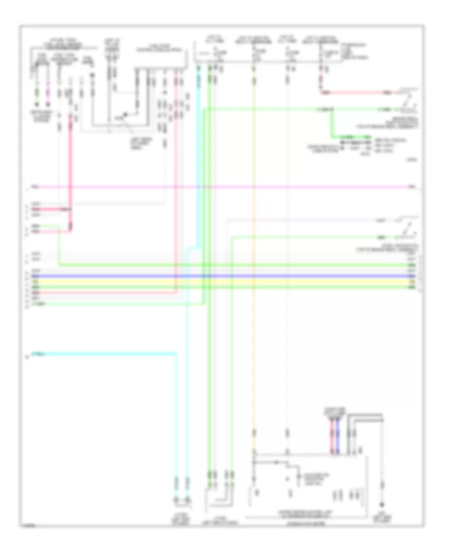
2.5L, Hybrid System Wiring Diagram (1 of 5) for Nissan Pathfinder S 2014
List of elements for 2.5L, Hybrid System Wiring Diagram (1 of 5) for Nissan Pathfinder S 2014:
- B148
- E131
- E207
- E214 (right front of engine compt)
- E57
- E68
- E9 (left rear of engine compt)
- Electric water pmp
- Electric water pump (left front of engine compt)
- Fuse 10a
- Fusible link v 50a
- Hi vol cooling water
- High voltage coolant temperature sensor (top left near cylinder bank)
- High voltage fuse, fusible link & relay box (rear of engine compt)
- Hot at all times
- Hpcm (center of dash)
- Inter lck sw
- Nca
- Pnk
- Pre-charge sig
- Red
- Self shut off relay
- Self shut off rly
- Sensor gnd
- Service plug
- Shield
- Str mtr rly ctrl sig
- System main rly 1
- System main rly 2
- Tan
- Temp sens
- Water pmp (feed back)
2.5L, Hybrid System Wiring Diagram (2 of 5) for Nissan Pathfinder S 2014
List of elements for 2.5L, Hybrid System Wiring Diagram (2 of 5) for Nissan Pathfinder S 2014:
- (left side of engine compt) j/c e21
- 44g
- 78g
- Avcc-mvpres
- Batt current sens
- Batt temp sens
- Bcm (body control module) (left side of dash)
- Brake vacuum sensor (on brake vacuum booster assembly)
- Brk vacuum sw
- Can-h
- Can-l
- Computer data lines system
- Cpu
- E119
- E120
- E132
- E15 (left rear of engine compt)
- E152
- E57
- E57 f1
- E9 (left rear of engine compt)
- F24
- Fuse & fusible link box (left side of engine compt)
- Fuse 10a
- Fusible link k 40a
- Gnd
- Gnda-mvpres
- Hot at all times
- Hot w/ ignition relay 1 energized
- Hpcm (center of dash)
- Ipdm e/r (intelligent power distribution module engine room) (left rear of engine compt)
- M18
- M19
- M31
- Mvpres
- P/n sig
- Pnk
- Pwr sply
- Red
- Sens gnd
- Sens pwr sply
- Shield
- Shift n/p
- Starter relay
- Starter relay out
- Str mtr status sig
- Tan
- Transmission range switch (left side of transmission)
2.5L, Hybrid System Wiring Diagram (3 of 5) for Nissan Pathfinder S 2014
List of elements for 2.5L, Hybrid System Wiring Diagram (3 of 5) for Nissan Pathfinder S 2014:
- (or red)
- 80g
- 81g
- Ascd steering switch
- B135
- B148
- Batt volt
- Battery current/temperature sensor (on battery)
- Battery temperature sensor
- Brk pdl position sw
- Can-h
- Can-l
- Cancel switch
- Coast/ set switch
- Computer data lines system
- Dc/dc con volt stbl sig
- Dc/dc converter (right side of cargo area)
- E130
- E15 (left rear of engine compt)
- E57
- E68
- Gnd
- Hev system can-h
- Hev system can-l
- Hpcm (center of dash)
- Ign sig
- Ign sw
- M149
- M30
- M31 e152
- Pnk
- Position sens 1
- Position sens 2
- Pwr sply
- Red
- Sens gnd
- Sens pwr sply
- Shield
- Spiral cable (combination switch) (steering column)
- Stop lmp sw
- Switch (main) on/off
- Switch accel/res
- Tan
2.5L, Hybrid System Wiring Diagram (4 of 5) for Nissan Pathfinder S 2014
List of elements for 2.5L, Hybrid System Wiring Diagram (4 of 5) for Nissan Pathfinder S 2014:
- (or red)
- (w/ information display)
- Accelerator pedal position sensor (top of accelerator pedal assembly)
- Brake pedal position switch (top of brake pedal assembly)
- Brk pdl pos sw
- Can-h
- Can-l
- Combination meter
- Computer data lines system
- E16
- E28
- Engine control module (ecm) (left front of engine compt)
- Ev ind lamp
- Fuse 10a
- Fuse 30 10a
- Fuse 5a
- Fuse block (j/b) (left end of dash)
- Hot at all times
- Hot w/ ignition relay 2 energized
- Hybrid system warning lamp
- J/c e01 (left end of dash)
- J/c e22 (left end of dash)
- M24
- M57 (left side of dash)
- Pnk
- Red
- Sensor 1
- Sensor 2
- Stop lamp switch (top of brake pedal assembly)
- Stop lmp sw
- Tan
- Unified meter control unit
2.5L, Hybrid System Wiring Diagram (5 of 5) for Nissan Pathfinder S 2014
List of elements for 2.5L, Hybrid System Wiring Diagram (5 of 5) for Nissan Pathfinder S 2014:
- 3-phase
- B117 (behind right rear quarterpanel)
- B131
- B148
- Bat
- Can-h
- Can-l
- Computer data lines system
- Cvt unit (left side of transmission)
- E15 (left rear of engine compt)
- E350
- E356
- E57
- E60
- E68
- F37
- F46
- Gnd 1
- Gnd 2
- Ignsw
- J/c f02 (left front of engine compt)
- Li-ion battery (right side of cargo area)
- Opsns+
- Opsns-
- Pnk
- Pre chg rly v
- Rly 1 v
- Rly 2 gnd
- Rly1 gnd
- Rly2 v
- Sd sw (+)
- Sdsw(-)
- Shield
- Tan
- Tmgnd
- Traction motor
- Traction motor inverter (left rear of engine)
- Traction motor temperature sensor
- Vb1
- Vb2
- Vbgnd1
- Vbgnd2
- Vign
3.5L
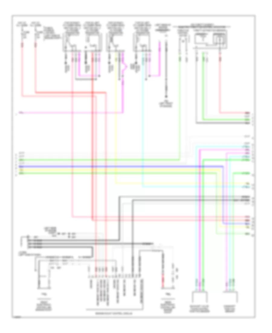
3.5L, Engine Performance Wiring Diagram (1 of 6) for Nissan Pathfinder S 2014
List of elements for 3.5L, Engine Performance Wiring Diagram (1 of 6) for Nissan Pathfinder S 2014:
- (left rear of engine) condenser 1
- (top of left cylinder bank) ignition coil 2 (w/ power transistor)
- (top of left cylinder bank) ignition coil 4 (w/ power transistor)
- (top of left cylinder bank) ignition coil 6 (w/ power transistor)
- (top of right cylinder bank) ignition coil 1 (w/ power transistor)
- (top of right cylinder bank) ignition coil 3 (w/ power transistor)
- (top of right cylinder bank) ignition coil 5 (w/ power transistor)
- A/f sens 1 htr (bank 1)
- A/f sens 1 htr (bank 2)
- E9 (left rear of engine compt)
- Ecm (left front of engine compt)
- Ecm ground
- Ecm rly (self shut-off)
- Electronic ctrl eng sol vlv
- Eng oil press sens
- F51
- F52
- F59 (left front of engine)
- Fuel inj 1
- Fuel injector 2
- Fuel injector 3
- Fuel injector 4
- Fuel injector 4 (left side of intake manifold)
- Fuel injector 5
- Fuel injector 6
- Fuel pump rly
- Heated o2 sens 2 htr 1(bank 1)
- Heated o2 sens 2 htr 2(bank 2) evap canister purge vol ctrl sol valve
- Heated oxygen sens 2 (bank 1)
- Heated oxygen sens 2 (bank 2)
- Heated oxygen sensor 2 (bank 1) (in exhaust, downstream of right three way catalyst)
- Heated oxygen sensor 2 (bank 2) (in exhaust, downstream of left three way catalyst)
- Ign sig 1
- Ign sig 2
- Ign sig 3
- Ign sig 4
- Ign sig 5
- Ign sig 6
- Intake vlv timing ctrl sol vlv (bank 2)
- J/c f04 (left front of engine compt)
- Nca
- Plug spark
- Pwr sply for ecm
- Red
- Refrigerant press sens
- Sens gnd
- Sens ground
- Sens pwr sply
- Sens pwr sply intake vlv timing ctrl sol vlv (bank 1)
- Spark plug
- Throttle ctrl mtr (close)
- Throttle ctrl mtr (open)
- Throttle ctrl mtr pwr sply
- Throttle ctrl mtr rly
- Throttle position sens 1
- Throttle position sens 2
- Vias ctrl sol valve 1
- Vias ctrl sol valve 2
- Wire loop
3.5L, Engine Performance Wiring Diagram (2 of 6) for Nissan Pathfinder S 2014
List of elements for 3.5L, Engine Performance Wiring Diagram (2 of 6) for Nissan Pathfinder S 2014:
- (left side of engine compt) j/c f07
- (left side of engine compt) j/c f08
- (right front of engine) j/c f09
- Fuel injector 1
- Fuel injector 2 (left side of intake manifold)
- Fuel injector 6 (left side of intake manifold)
- Fusible link box (battery) (near battery)
- Fusible link e 80a
- Hot at all times
- Intake valve timing control solenoid valve (bank 1) (front of right cylinder bank)
- Intake valve timing control solenoid valve (bank 2) (front of left cylinder bank)
- Red
- Vias control solenoid valve 1 (top of right cylinder bank)
- Vias control solenoid valve 2 (top of right cylinder bank)
3.5L, Engine Performance Wiring Diagram (3 of 6) for Nissan Pathfinder S 2014
List of elements for 3.5L, Engine Performance Wiring Diagram (3 of 6) for Nissan Pathfinder S 2014:
- Computer data lines system
- Cooling fans system
- Cpu
- E118
- E119
- E121
- E15 (left rear of engine compt)
- E2 f32
- E34 b40
- E9 (left rear of engine compt)
- Ecm relay
- Electric throttle control actuator (on throttle body)
- Electronic controlled engine mount control solenoid valve (left front of engine)
- Evap canister vent control valve (under spare tire housing)
- F19
- F24
- F32 e2
- Fuel pump relay
- Fuse 10a
- Fuse 15a
- Ignition relay 1
- Ipdm e/r (intelligent power distribution module engine room) (left rear of engine compt)
- J/c e05 (left side of engine compt)
- J/c f01 (left front of engine compt)
- Pnk
- Red
- Sensor 1
- Sensor 2
- Shield
- Throttle control motor
- Throttle control motor relay
- Throttle position sensor
3.5L, Engine Performance Wiring Diagram (4 of 6) for Nissan Pathfinder S 2014
List of elements for 3.5L, Engine Performance Wiring Diagram (4 of 6) for Nissan Pathfinder S 2014:
- (base of left " b" pillar) condenser 2
- (in fuel tank) fuel level sensor unit & fuel pump
- (left front of engine compt) j/c f04
- (on left exhaust manifold) air fuel ratio (a/f) sensor 1 (bank 2)
- (on right exhaust manifold) air fuel ratio (a/f) sensor 1 (bank 1)
- (right rear of engine) evap canister purge volume control solenoid valve
- B40 e34
- B43 e33
- B7 (left "c" pillar)
- Camshaft position sensor (phase) (bank 1) (rear of right cylinder bank)
- Camshaft position sensor (phase) (bank 2) (rear of left cylinder bank)
- Crankshaft position sensor (pos) (lower left rear of engine)
- E119
- F26 f201
- F32 e2
- F33 e19
- Fuel level sensor
- Fuel pump
- Fuel tank temperature sensor
- Instrument cluster system
- Ipdm e/r (intelligent power distribution e218 module engine room) (left rear of engine compt)
- J/c b01 (left "d" pillar)
- Knock sensor (bank 1) (under intake manifold, on right cylinder bank)
- Knock sensor (bank 2) (under intake manifold, on left cylinder bank)
- Pnk
- Red
- Refrigerant pressure sensor (front left side of radiator)
- Shield
3.5L, Engine Performance Wiring Diagram (5 of 6) for Nissan Pathfinder S 2014
List of elements for 3.5L, Engine Performance Wiring Diagram (5 of 6) for Nissan Pathfinder S 2014:
- (in right fuse & relay box) stop lamp relay
- (on air cleaner box) mass airflow sensor
- (top of brake pedal assembly) stop lamp switch
- 13p
- Bat
- Can-h
- Can-l
- Combination meter
- Computer data lines system
- E15 (left rear of engine compt)
- E28
- F33 e19
- Fuse 10a
- Fuse 5a
- Fuse block (j/b) (left end of dash)
- Gnd1
- Gnd2
- Hot at all times
- Hot w/ ignition relay 2 energized
- Ign
- Intake air temperature sensor
- M24
- M57 (left side of dash)
- Malfunction indicator lamp (mil)
- Pnk
- Red
- Shield
- Tan
- Transmission range switch (left side of transmission)
- Unified meter control unit (w/ information display)
3.5L, Engine Performance Wiring Diagram (6 of 6) for Nissan Pathfinder S 2014
List of elements for 3.5L, Engine Performance Wiring Diagram (6 of 6) for Nissan Pathfinder S 2014:
- (left end of dash) j/c e01
- (left front of engine compt) j/c f04
- (lower right front of engine) engine oil temperature sensor
- (on battery) battery current sensor
- (rear of left cylinder bank) engine coolant temperature sensor
- A/f sens 1 (bank 1)
- A/f sens 1 (bank 2)
- Accelerator pdl pos sens 1
- Accelerator pdl pos sens 2
- Accelerator pedal position sensor (top of accelerator pedal assembly)
- Ascd brake sw
- Ascd steering sw
- Batt current sens
- Batt temp sens
- Brake pedal position switch (top of brake pedal assembly)
- Can-h
- Can-l
- Computer data lines system
- Crankshaft pos sens (pos)
- Cruise control system
- Data link connector
- E16
- E34 b40
- E9 (left rear of engine compt)
- Ecm (left front of engine compt)
- Ecm gnd
- Eng coolant temp sens
- Eng oil temp sens
- Engine oil pressure sensor (lower front of engine)
- Evap canister vent ctrl vlv
- Evap control system pressure sensor (under spare tire housing)
- Evap ctrl sys press sens
- F32
- F52
- Fuel tank temp sens
- Ign sw
- Intake air temp sens
- J/c e01 (left end of dash)
- Knock sens (bank 1)
- Knock sens (bank 2)
- Mass air flow sens
- Pnk
- Pnp sig
- Pwr sply for ecm
- Red
- Sens gnd
- Sens gnd camshaft pos sens (phase) (bank 2) camshaft pos sens (phase) (bank 1)
- Sens pwr sig
- Sens pwr sply
- Sensor 1
- Sensor 2
- Shield
- Stp lp sw
- Tan