ENGINE PERFORMANCE
3.5L
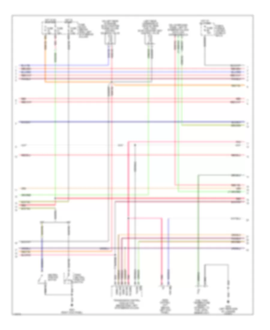
3.5L, Engine Performance Wiring Diagrams (1 of 4) for Nissan Pathfinder SE 2001

List of elements for 3.5L, Engine Performance Wiring Diagrams (1 of 4) for Nissan Pathfinder SE 2001:
- (on left rear of engine) iacv-aac valve
- (on top of engine) condenser
- A/c system
- Acpdcut
- Acrly
- Arcon
- Bstsw
- Cdcv
- Crtn
- Cvbv
- Cvtcl
- Cvtcr
- Defogger system, headlights system
- Engine control module (ecm) (behind center of dash)
- Evap
- Fprly
- G110 (left front of engine)
- G119 (right front of engine)
- Gnd-a
- Gnd-c
- Idle
- Ign 1
- Ign 2
- Ign 3
- Ign 4
- Ign 5
- Ign 6
- Ignition coils
- Ignsw
- Isc 1
- Isc 2
- Isc 3
- Isc 4
- Led
- Left intake valve timing control valve (on left side of engine)
- Load
- Neut
- O2hfl
- O2hfr
- O2hrl
- O2hrr
- Power steering oil pressure switch (lower right front of engine, on power steering high pressure tube)
- Pwst
- Red
- Right intake valve timing control valve (on right side of engine)
- Scv
- Ssoff
- Stsw
- Swirl control valve control solenoid valve (on top left of engine)
- Swirl control valve control vacuum check switch (near brake fluid reservoir)
- Tacho
- Vacuum cut valve by-pass valve (left rear underside of vehicle, near fuel tank)
- Vias
- Vias control solenoid valve (on top front of engine)
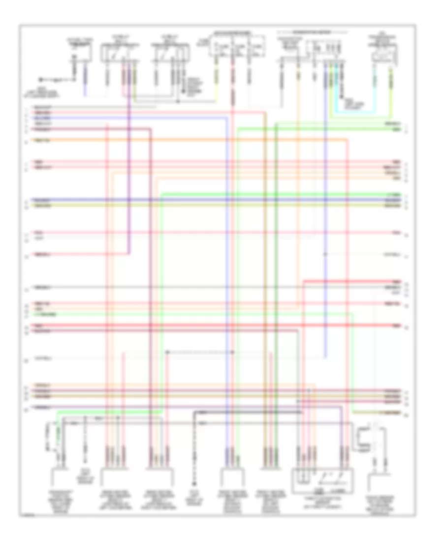
3.5L, Engine Performance Wiring Diagrams (2 of 4) for Nissan Pathfinder SE 2001
List of elements for 3.5L, Engine Performance Wiring Diagrams (2 of 4) for Nissan Pathfinder SE 2001:
- (left rear underside of vehicle, near fuel tank) evap canister vent control valve
- (on left rear of engine) evap canister purge volume control solenoid valve
- (on lower dash panel, left of steering column) data link connector (dlc)
- 10u
- 16u
- A/t
- Ascd control unit (behind left kick panel)
- Fuel tank temperature sensor (integral to fuel level sensor unit)
- Full sw
- Fuse & fusible link box (in relay box 2)
- Fuse 10a
- Fuse 15a
- Fuse 7.5a
- Fuse block (behind dash, left of steering column)
- G203 (right kick panel)
- G404 (left rear side of luggage compt)
- Hot at all times
- Hot in on or start
- Hot in start
- Idle sw
- Lan
- M/t
- Neutral position switch
- P/n
- Park/ neutral position switch
- Pnk
- Red
- Sens g
- Sens p
- Tacho
- Th sens
- Transmission control module (tcm) (behind dash, left of steering column)
- Vsp (in)
3.5L, Engine Performance Wiring Diagrams (3 of 4) for Nissan Pathfinder SE 2001
List of elements for 3.5L, Engine Performance Wiring Diagrams (3 of 4) for Nissan Pathfinder SE 2001:
- (front of right front fender) g101
- (in fuel tank) fuel pump
- (in relay box 1) fuel pump relay 1
- (in relay box 2) fuel pump relay 2
- (on transmission) vehicle speed sensor
- 17u
- 26u
- 37u
- Closed
- Combination meter
- Crankshaft position sensor (ref) (on lower front of engine)
- Front heated oxygen sensor (bank 1) (on right exhaust manifold)
- Front heated oxygen sensor (bank 2) (on left exhaust manifold)
- Fuse 10a
- Fuse 15a
- Fuse block
- G110 (left front of engine)
- G202 (left side of dash)
- G404 (left rear side of luggage compt)
- Hot in on or start
- Knock sensor (on top rear of engine, below intake manifold)
- Malfunction ind lamp
- Nca
- Pnk
- Rear heated oxygen sensor (bank 1) (upstream of right converter)
- Rear heated oxygen sensor (bank 2) (upstream of left converter)
- Red
- Sig tach
- Throttle position sensor (on throttle body)
- Vsp
- Vss
- Wide open
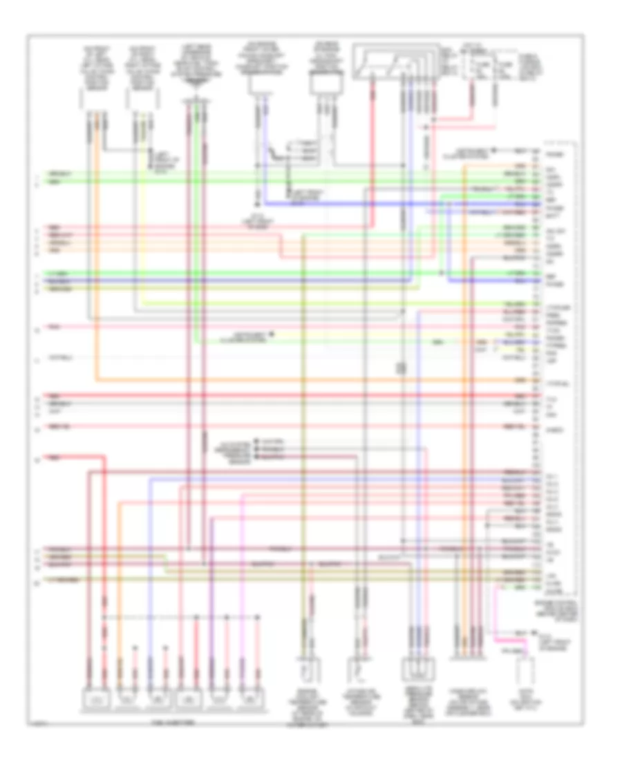
3.5L, Engine Performance Wiring Diagrams (4 of 4) for Nissan Pathfinder SE 2001
List of elements for 3.5L, Engine Performance Wiring Diagrams (4 of 4) for Nissan Pathfinder SE 2001:
- (left front nca of engine) g110
- (left front of engine) g110
- (left rear underside of vehicle, near fuel tank) evap control system pressure sensor
- (on engine front cover, facing camshaft sprocket) camshaft position sensor (phase)
- (on front of left cyl head) left intake valve timing control position sensor
- (on front of right cyl head) right intake valve timing control position sensor
- (on rear of engine oil pan) crankshaft position sensor (pos)
- A/c system (refrigerant pressure sensor)
- Absolute pressure sensor (behind center of dash, near ecm)
- Adj sw
- Avcc
- Batt
- Check
- Ecm relay (in relay box 2)
- Engine control module (ecm) (behind center of dash)
- Engine coolant temperature sensor (at rear of engine, on water outlet)
- Fgage+
- Fgage-
- Ftpres
- Fuel injectors
- Fuse & fusible link box (in relay box 2)
- Fuse 10a
- Fuse 7.5a
- G110 (left front of eng)
- G110 (left front of engine)
- Gnd-e
- Hot at all times
- Imline
- Inj 1
- Inj 2
- Inj 3
- Inj 4
- Inj 5
- Inj 6
- Instrument cluster system
- Intake air temperature sensor (in air duct housing)
- Kline
- Knk
- Lan
- Mass airflow sensor (on air intake assembly, near air cleaner box)
- Nats immu (on ignition key cyl)
- Nca
- O2sfl
- O2sfr
- O2srl
- O2srr
- Pdpres
- Phase
- Pnk
- Pos
- Pres
- Qa+
- Qa-
- Red
- Ref
- Tvo
- Tvoo
- Vsp
- Vtcpusl
- Vtcpusr