ENGINE PERFORMANCE
4.0L
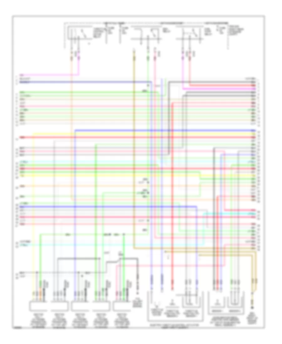
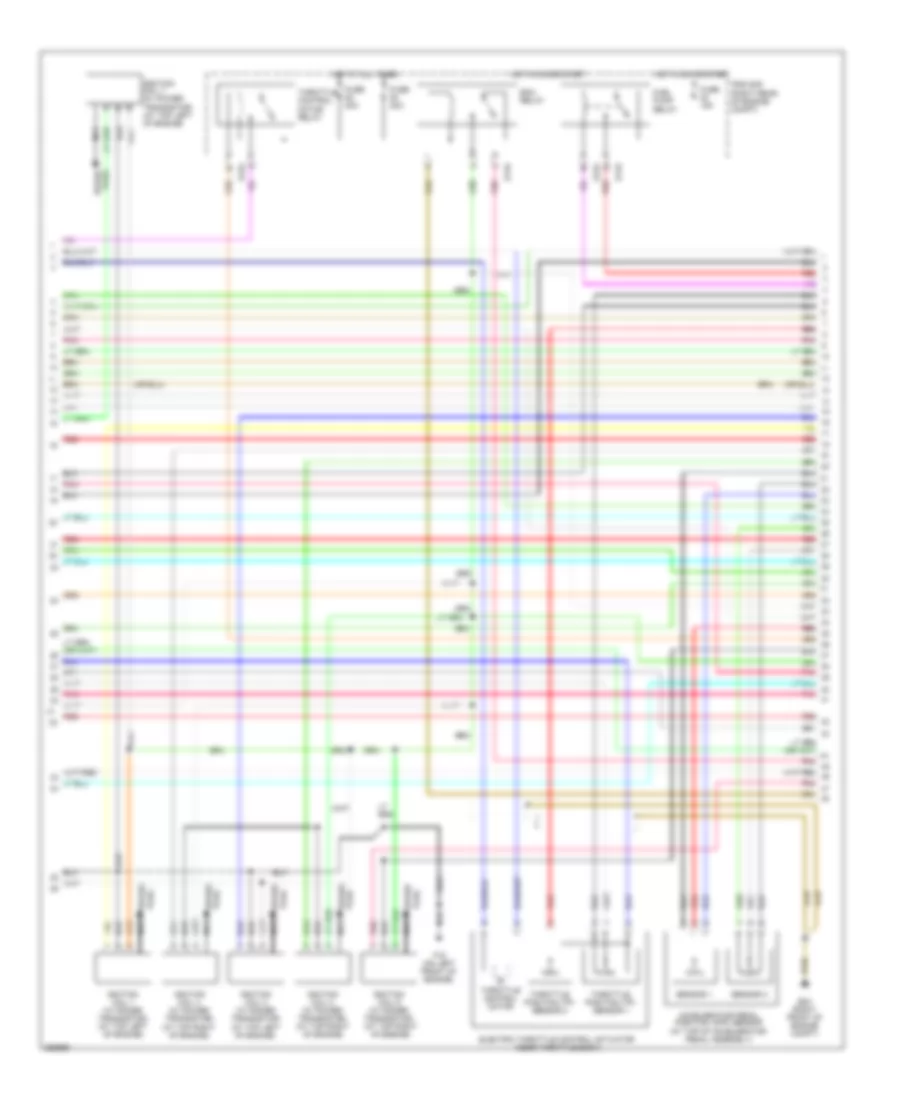
4.0L, Engine Performance Wiring Diagram (1 of 4) for Nissan Pathfinder SE 2008

List of elements for 4.0L, Engine Performance Wiring Diagram (1 of 4) for Nissan Pathfinder SE 2008:
- (at top left of engine) fuel injector
- (at top right of engine) fuel injector
- (on left side of engine) f16
- (right front of engine compt)
- (right front of engine compt) e24
- 15p
- Af+1
- Af+2
- Af-1
- Af-h1
- Af-h2
- Avcc
- Avcc (pdp)
- Avcc 2
- Battery current sensor (right front of engine compt)
- C-vtc (l)
- C-vtc (r)
- Combination meter
- Computer data lines system
- Condenser 1 (on top of engine)
- Crankshaft position sensor (pos) (at right rear of engine)
- E24
- Ecm (right rear of engine compt)
- Evap
- Evap canister purge volume control solenoid valve (on left side of engine)
- Ftprs
- Fuse 10a
- Fuse block (j/b) (behind right end of dash)
- Gnd
- Hot in on or start
- Ignition coil 5 (w/ power transistor) (at top right of engine)
- Inj 1
- Inj 2
- Inj 3
- Inj 4
- Inj 5
- Inj 6
- Intake valve timing control position sensor (bank 2) (left front of engine)
- Knk 1
- Knk 2
- Knock sensor (bank 1) (on right side of engine)
- Knock sensor (bank 2) (on right rear of engine)
- M24
- Malfunction indicator lamp
- Motor 1
- Motor 2
- Nca
- O2hrl
- O2hrr
- O2srl
- Phase (lh)
- Pnk
- Pos
- Ps pres
- Pwr sup
- Qa+
- Red
- Refrigerant pressure sensor (right front of engine compt)
- Shield
- Sig
- Spark plug
- Tps 1
- Unified meter control unit
- Vias
- Vmot
- Vtcpusr
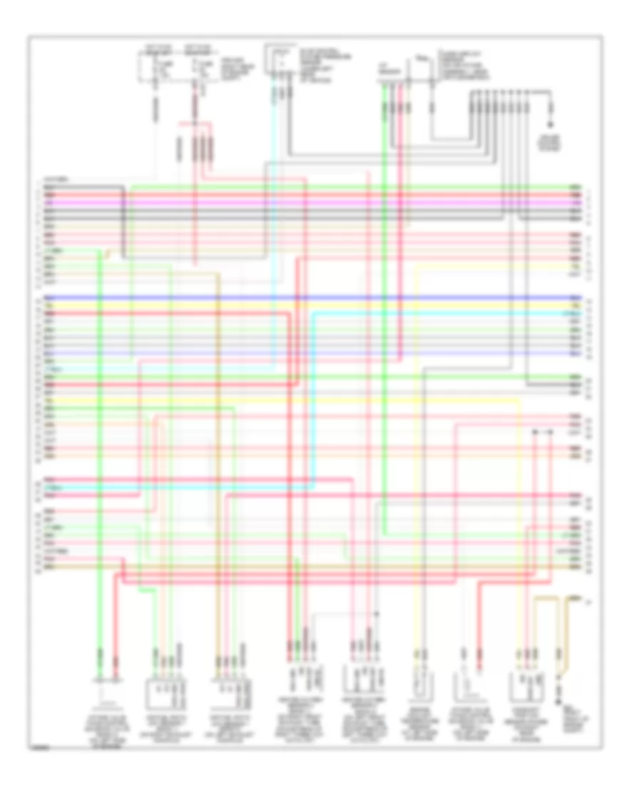
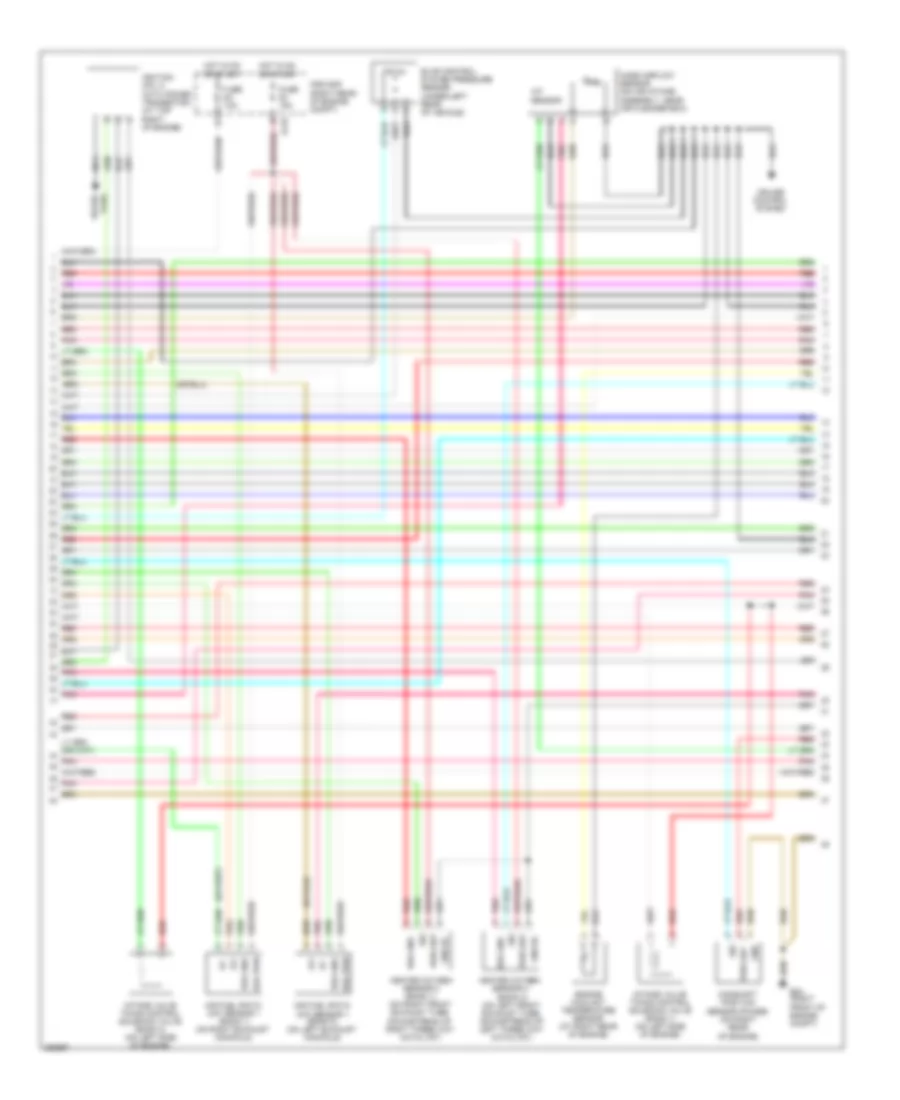
4.0L, Engine Performance Wiring Diagram (2 of 4) for Nissan Pathfinder SE 2008
List of elements for 4.0L, Engine Performance Wiring Diagram (2 of 4) for Nissan Pathfinder SE 2008:
- (at top left of engine)
- (at top right of engine)
- Accelerator pedal position (app) sensor (at top of accelerator pedal assembly)
- E119
- E122
- E24 (right front of engine compt)
- Ecm relay
- Electric throttle control actuator (near throttle body)
- F16 (on left side of engine)
- Fuel pump relay
- Fuse 15a
- Fuse 20a
- Hot at all times
- Hot in on or start
- Ignition coil 1 (w/ power transistor) (at top right of engine)
- Ignition coil 2 (w/ power transistor) (at top left of engine)
- Ignition coil 3 (w/ power transistor)
- Ignition coil 4 (w/ power transistor)
- Ignition coil 6 (w/ power transistor) (at top left of engine)
- Ipdm e/r (right rear of engine compt)
- Nca
- Plug spark
- Pnk
- Red
- Sensor 1
- Sensor 2
- Spark plug
- Throttle control motor
- Throttle control motor relay
- Throttle position (tp) sensor 1
- Throttle position (tp) sensor 2
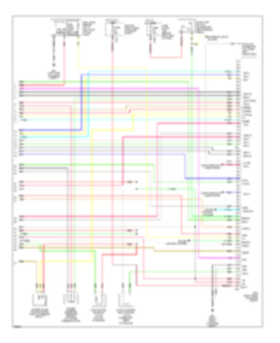
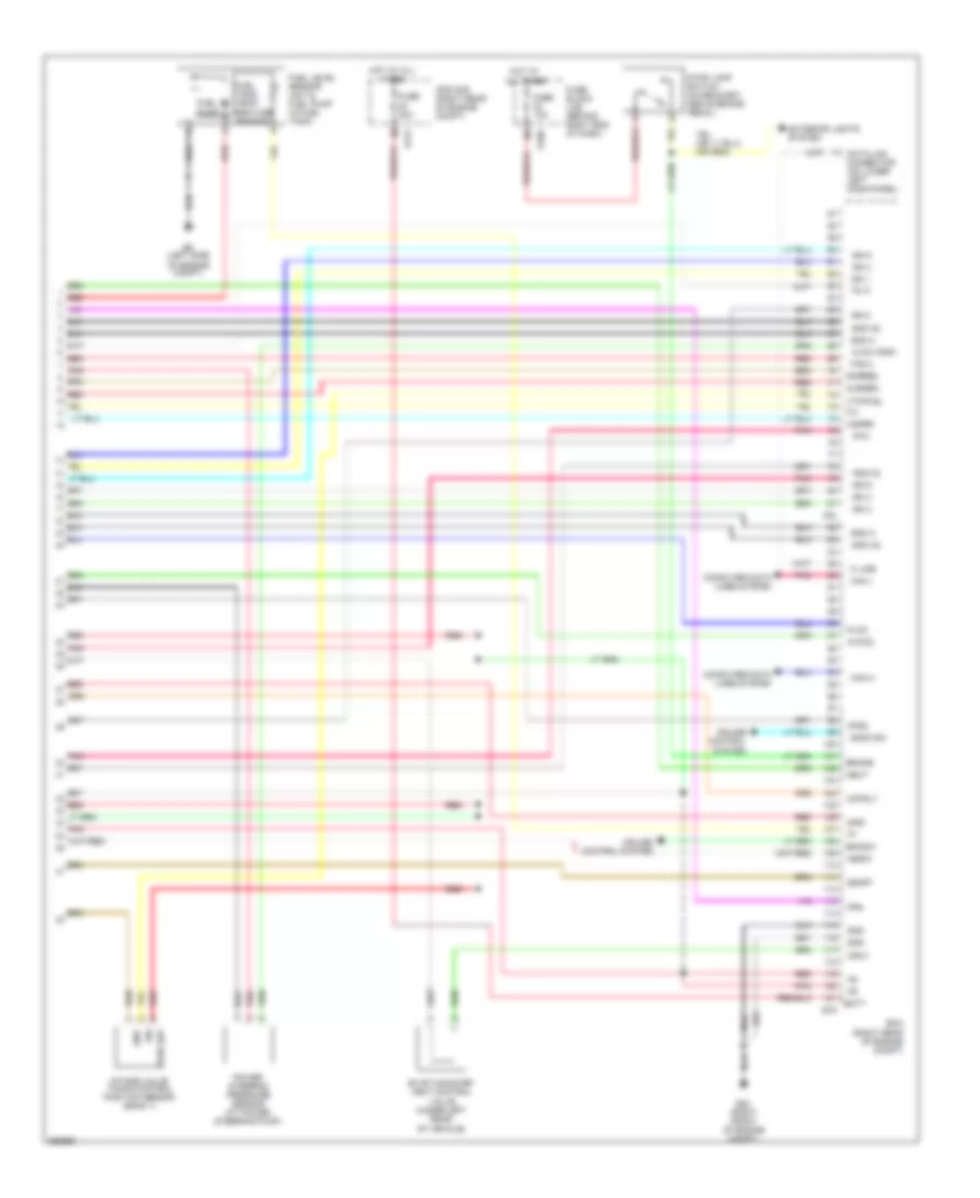
4.0L, Engine Performance Wiring Diagram (3 of 4) for Nissan Pathfinder SE 2008
List of elements for 4.0L, Engine Performance Wiring Diagram (3 of 4) for Nissan Pathfinder SE 2008:
- Af+
- Af-
- Air fuel ratio (a/f) sensor 1 (bank 1) (on right exhaust manifold)
- Air fuel ratio (a/f) sensor 1 (bank 2) (on left exhaust manifold)
- Camshaft position sensor (phase) (on right rear of engine)
- Cruise control system
- E119
- E24 (right front of engine compt)
- Engine coolant temperature sensor (at left side of engine)
- Evap control system pressure sensor (under left rear of vehicle)
- Fuse 15a
- Gnd
- Gnd 02
- Hea gnd
- Hea pwr
- Heated oxygen sensor 2 (bank 1) (on right front exhaust tube, downstream of right three way catalyst)
- Heated oxygen sensor 2 (bank 2) (on left front exhaust tube, downstream of left three way catalyst)
- Hot in on or start
- Iat sensor
- Intake valve timing control solenoid valve (bank 1) (on left side of engine)
- Intake valve timing control solenoid valve (bank 2) (on left side of engine)
- Ipdm e/r (right rear of engine compt)
- Mass airflow sensor (on air intake assembly, near air cleaner box)
- Pnk
- Pwr sup
- Red
- Sig
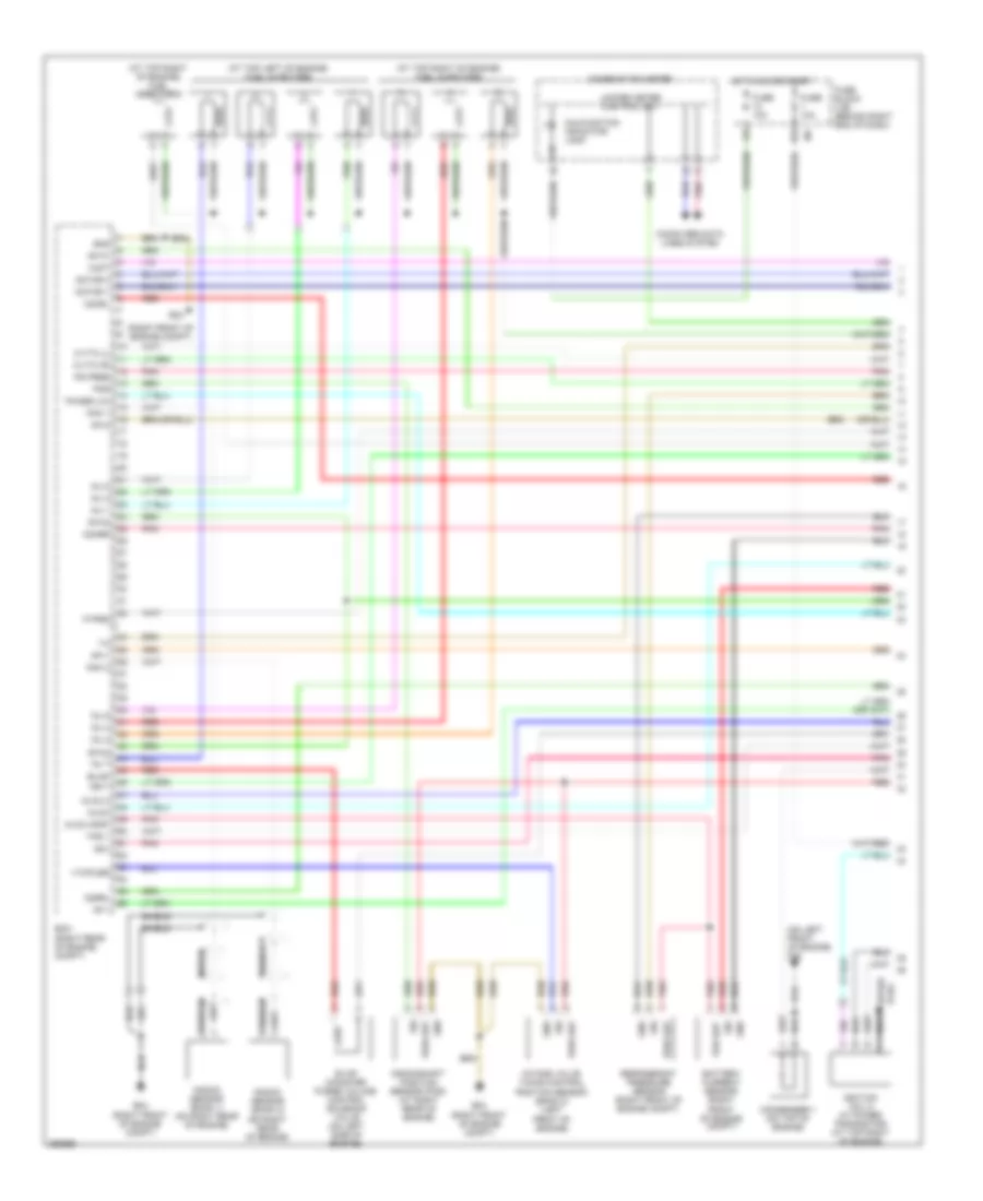
4.0L, Engine Performance Wiring Diagram (4 of 4) for Nissan Pathfinder SE 2008
List of elements for 4.0L, Engine Performance Wiring Diagram (4 of 4) for Nissan Pathfinder SE 2008:
- Af-2
- Aps1
- Aps2
- Ascd sw
- Avcc
- Avcc (psp)
- Avcc2
- Batt
- Bncsw
- Brake
- Can h
- Can l
- Cdcv
- Computer data lines system
- Cruise control system
- Cursen
- Data link connector (on lower left dash panel)
- E121
- E16
- E160
- E24 (right front of engine compt)
- E9 (left side of engine compt)
- Ecm (right rear of engine compt)
- Evap canister vent control valve (under left rear of vehicle)
- Exterior lights system
- F54
- Fpr
- Fuel level sensor unit & fuel pump (in fuel tank)
- Fuel pump
- Fuel tank temp- erature sensor
- Fuse 10a
- Fuse 20a
- Fuse block (j/b) (behind right end of dash)
- Gnd
- Gnd 02
- Gnd a
- Gnd a2
- Hot at all times
- Ign 1
- Ign 2
- Ign 3
- Ign 4
- Ign 5
- Ign 6
- Ignsw
- Intake valve timing control position sensor (bank 1)
- Ipdm e/r (right rear of engine compt)
- K line
- Motrly
- Neut
- O2srr
- Pdpres
- Pnk
- Power steering pressure sensor (at power steering pump)
- Pwr sup
- Red
- Sig
- Ssoff
- Stop lamp switch (on bracket, above brake pedal)
- Tps 2
- Vias control solenoid valve (on top of engine)
- Vtcpusl
5.6L
5.6L, Engine Performance Wiring Diagram (1 of 4) for Nissan Pathfinder SE 2008
List of elements for 5.6L, Engine Performance Wiring Diagram (1 of 4) for Nissan Pathfinder SE 2008:
- (at top left of engine) fuel injectors
- (at top right of engine) fuel injector 8
- (at top right of engine) fuel injectors
- (on left front of engine) f16
- (right front of engine compt)
- 15p
- Af+1
- Af+2
- Af-1
- Af-h1
- Af-h2
- Avcc
- Avcc (pdp)
- Avcc 2
- Battery current sensor (right front of engine compt)
- C-vtc (l)
- C-vtc (r)
- Combination meter
- Computer data lines system
- Condenser 1 (on top of engine)
- Crankshaft position sensor (pos) (at right rear of engine)
- E24
- Ecm (right rear of engine compt)
- Evap
- Evap canister purge volume control solenoid valve (on left side of engine)
- Ftprs
- Fuse 10a
- Fuse block (j/b) (behind right end of dash)
- Gnd
- Hot in on or start
- Ign 7
- Ignition coil 5 (w/ power transistor) (at top right of engine)
- Inj 1
- Inj 2
- Inj 3
- Inj 4
- Inj 5
- Inj 6
- Inj 7
- Intake valve timing control position sensor (bank 2) (left front of engine)
- Knk 1
- Knk 2
- Knock sensor (bank 1) (on right rear of engine)
- Knock sensor (bank 2) (on right rear of engine)
- Malfunction indicator lamp
- Motor 1
- Motor 2
- Nca
- O2hrl
- O2hrr
- O2srl
- Per sup
- Phase (lh)
- Pnk
- Pos
- Ps pres
- Pwr sup
- Qa+
- Red
- Refrigerant pressure sensor (right front of engine compt)
- Shield
- Sig
- Spark plug
- Tps 1
- Unified meter control unit
- Vmot
- Vtcpusr
5.6L, Engine Performance Wiring Diagram (2 of 4) for Nissan Pathfinder SE 2008
List of elements for 5.6L, Engine Performance Wiring Diagram (2 of 4) for Nissan Pathfinder SE 2008:
- (at top left of engine)
- (at top right of engine)
- Accelerator pedal position (app) sensor (at top of accelerator pedal assembly)
- E119
- E122
- E24 (right front of engine compt)
- Ecm relay
- Electric throttle control actuator (near throttle body)
- F16 (on left front of engine)
- Fuel pump relay
- Fuse 15a
- Fuse 20a
- Hot at all times
- Hot in on or start
- Ignition coil 1 (w/ power transistor) (at top left of engine)
- Ignition coil 2 (w/ power transistor) (at top right of engine)
- Ignition coil 3 (w/ power transistor)
- Ignition coil 4 (w/ power transistor)
- Ignition coil 6 (w/ power transistor) (at top right of engine)
- Ignition coil 7 (w/ power transistor) (at top left of engine)
- Ipdm e/r (right rear of engine compt)
- Nca
- Plug spark
- Pnk
- Red
- Sensor 1
- Sensor 2
- Spark plug
- Throttle control motor
- Throttle control motor relay
- Throttle position (tp) sensor 1
- Throttle position (tp) sensor 2
5.6L, Engine Performance Wiring Diagram (3 of 4) for Nissan Pathfinder SE 2008
List of elements for 5.6L, Engine Performance Wiring Diagram (3 of 4) for Nissan Pathfinder SE 2008:
- Af+
- Af-
- Air fuel ratio (a/f) sensor 1 (bank 1) (on right exhaust manifold)
- Air fuel ratio (a/f) sensor 1 (bank 2) (on left exhaust manifold)
- Camshaft position sensor (phase) (on right rear of engine)
- Cruise control system
- E119
- E24 (right front of engine compt)
- Engine coolant temperature sensor (at right rear of engine)
- Evap control system pressure sensor (under left rear of vehicle)
- Fuse 15a
- Gnd
- Gnd 02
- Hea gnd
- Hea pwr
- Heated oxygen sensor 2 (bank 1) (on right front exhaust tube, downstream of right three way catalyst)
- Heated oxygen sensor 2 (bank 2) (on left front exhaust tube, downstream of left three way catalyst)
- Hot in on or start
- Iat sensor
- Ignition coil 8 (with power transistor) (at top right of engine)
- Intake valve timing control solenoid valve (bank 1) (on left side of engine)
- Intake valve timing control solenoid valve (bank 2) (on left side of engine)
- Ipdm e/r (right rear of engine compt)
- Mass airflow sensor (on air intake assembly, near air cleaner box)
- Nca
- Pnk
- Pwr sup
- Red
- Sig
- Spark plug
5.6L, Engine Performance Wiring Diagram (4 of 4) for Nissan Pathfinder SE 2008
List of elements for 5.6L, Engine Performance Wiring Diagram (4 of 4) for Nissan Pathfinder SE 2008:
- Af-2
- Aps1
- Aps2
- Ascd sw
- Avcc
- Avcc (psp)
- Avcc2
- Batt
- Bncsw
- Brake
- Can h
- Can l
- Cdcv
- Computer data lines system
- Cruise control system
- Cursen
- Data link connector (on lower left dash panel)
- E121
- E16
- E160
- E24 (right front of engine compt)
- E9 (left side of engine compt)
- Ecm (right rear of engine compt)
- Evap canister vent control valve (under left rear of vehicle)
- Exterior lights system
- F54
- Fpr
- Fuel level sensor unit & fuel pump (in fuel tank)
- Fuel pump
- Fuel tank temp- erature sensor
- Fuse 10a
- Fuse 20a
- Fuse block (j/b) (behind right end of dash)
- Gnd
- Gnd 02
- Gnd a
- Gnd a2
- Hot at all times
- Ign 1
- Ign 2
- Ign 3
- Ign 4
- Ign 5
- Ign 6
- Ign 8
- Ignsw
- Inj 8
- Intake valve timing control position sensor (bank 1)
- Ipdm e/r (right rear of engine compt)
- K line
- Motrly
- Neut
- O2srr
- Pdpres
- Pnk
- Power steering pressure sensor (at power steering pump)
- Pwr sup
- Red
- Sig
- Ssoff
- Stop lamp switch (on bracket, above brake pedal)
- Tps 2
- Vtcpusl