ENGINE PERFORMANCE
3.5L
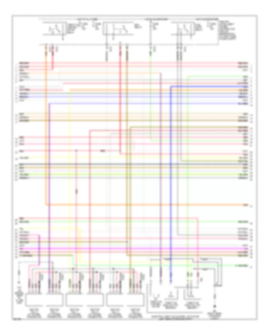
3.5L, Engine Performance Wiring Diagram (1 of 4) for Nissan Quest 2007

List of elements for 3.5L, Engine Performance Wiring Diagram (1 of 4) for Nissan Quest 2007:
- (right rear of engine compt)
- 02hr2
- 02sr2
- A/f sns 1
- A/f-h2
- A/f-ip2
- A/f-un1
- A/f-vm1
- A/f-vm2
- Af-h1
- At n sw
- At pn ecm
- At pn sw
- Avcc
- Avcc pdpres
- Avcc2
- C-vtc l
- C-vtc r
- Camshaft position sensor (phase) (bank 1) (top right rear of engine)
- Camshaft position sensor (phase) (bank 2) (left rear of engine)
- Combination meter
- Computer data lines system
- Condenser 1 (left side of engine)
- Crankshaft position sensor (pos) (left rear of engine)
- Ecm (right rear of engine compt)
- Egr volume control valve (right rear of engine)
- Egrts
- Enmn 1
- Enmn 2
- Erg 1
- Erg 2
- Erg 3
- Erg 4
- Evap
- Evap canister purge volume control solenoid valve (right rear of engine)
- F16 (on eng, near oil filler cap)
- Ftprs
- Fuel injector
- Gnd
- Ign 5 sig
- Inj 1 ctrl
- Inj 2 ctrl
- Inj 3 ctrl
- Inj 4 ctrl
- Inj 5 ctrl
- Inj 6 ctrl
- Knk1
- Knock sensor (top of engine)
- Malfunction indicator lamp
- Motor 1
- Motor 2
- Nca
- O2hr1
- Phase lh
- Phase rh
- Pnk
- Pnk/red
- Pos
- Pspres
- Qa+
- Red
- Refrigerant pressure sensor (right front of engine compt)
- Tps 1
- Unified meter control unit
- Vias ctrl sol
- Vmot
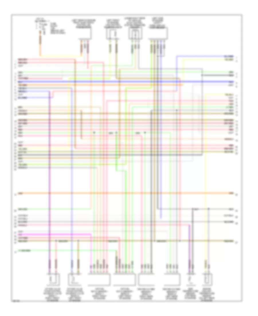
3.5L, Engine Performance Wiring Diagram (2 of 4) for Nissan Quest 2007
List of elements for 3.5L, Engine Performance Wiring Diagram (2 of 4) for Nissan Quest 2007:
- (on engine, near oil filler cap)
- E121
- E122
- E124
- E9 (right rear of engine compt)
- Ecm relay
- Electric throttle control actuator (left rear of engine compt)
- F16
- F50
- Fuel pump relay
- Fuse 15a
- Hot at all times
- Hot in on or start
- Ignition coil 1 (w/ power transistor)
- Ignition coil 2 (w/ power transistor)
- Ignition coil 3 (w/ power transistor)
- Ignition coil 4 (w/ power transistor)
- Ignition coil 5 (w/ power transistor)
- Ignition coil 6 (w/ power transistor)
- Ipdm e/r (intelligent power distribution module engine room) (at right side of eng compt)
- Nca
- Pnk
- Red
- Spark plug
- Throttle control motor
- Throttle control motor relay
- Throttle position (tp) sensor 1
- Throttle position (tp) sensor 2
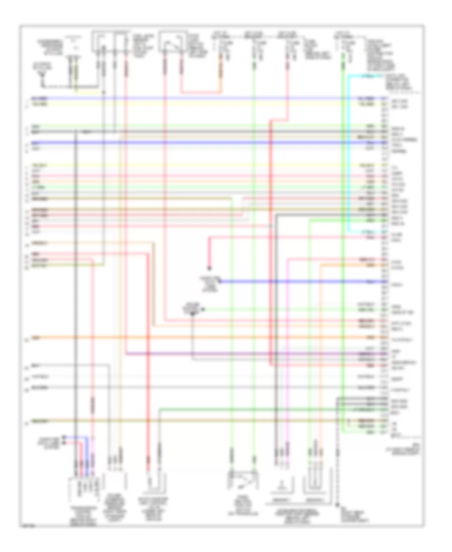
3.5L, Engine Performance Wiring Diagram (3 of 4) for Nissan Quest 2007
List of elements for 3.5L, Engine Performance Wiring Diagram (3 of 4) for Nissan Quest 2007:
- (left front of engine) vias control solenoid valve
- (left rear of engine) front electronic controlled engine mount
- (left side of engine compt)
- (under right rear of vehicle) evap control system pressure sensor
- Air fuel ratio sensor 1 (bank 1) (right front of engine)
- Air fuel ratio sensor 1 (bank 2) (left front of engine)
- E30
- Egr temperature sensor (top rear of engine)
- Engine coolant temperature sensor (on left rear of engine)
- Fuse 15a
- Fuse block (j/b) (behind left side of dash)
- Heated oxygen sensor 2 (bank 1) (right rear of engine)
- Heated oxygen sensor 2 (bank 2) (left rear of engine)
- Hot at all times
- Intake valve timing control solenoid valve (bank 1) (right front of engine)
- Intake valve timing control solenoid valve (bank 2) (left front of engine)
- Mass airflow (maf) sensor
- Pnk
- Red
3.5L, Engine Performance Wiring Diagram (4 of 4) for Nissan Quest 2007
List of elements for 3.5L, Engine Performance Wiring Diagram (4 of 4) for Nissan Quest 2007:
- (at right "b" pillar) b117
- A/f-ia1
- A/f-ia2
- A/f-un2
- Accelerator pedal position (app) sensor (behind left side of dash)
- Aps1
- Aps2
- Ascd brk sw
- Ascd st sw
- Avcc
- Avcc pspres
- Avcc2
- Batt
- Can h
- Can l
- Can-h
- Can-l
- Cdcv
- Computer data lines system
- Condenser 2 (near base of right "b" pillar)
- Cruise control system
- Data link connector (below left side of dash)
- E124
- E30
- E9 (right rear of engine compartment)
- Ecm (at right rear of engine compt)
- Ecm gnd
- Evap canister vent control valve (under left rear of vehicle)
- F pmp rly
- Fuel level sensor unit & fuel pump (in fuel tank)
- Fuse 10a
- Fuse 15a
- Fuse block (j/b) (behind left side of dash)
- Gnd
- Gnd a
- Gnd a2
- Gnd-a2
- Hot at all times
- Hot in on or start
- Ign 1 sig
- Ign 2 sig
- Ign 3 sig
- Ign 4 sig
- Ign 6 sig
- Ign sw
- Ipdm e/r (intelligent power distribution module engine room) (at right side of eng compt)
- Kline
- Neutl
- O2sr1
- Park/ neutral position switch (on transaxle)
- Pdpres
- Pnk
- Power steering pressure sensor (right rear of engine compt)
- P_n_sw
- Red
- Sen gnd
- Sensor 1
- Sensor 2
- Ssoff
- Stop lamp switch (behind left side of dash)
- Stp lp sw
- Tc mtr rly
- Tps 2
- Transmission control module (behind right side of dash)