ENGINE PERFORMANCE
3.0L
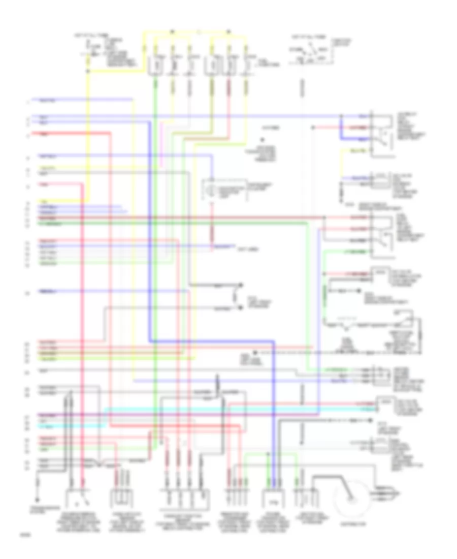
3.0L, Engine Performance Wiring Diagrams (1 of 2) for Nissan Quest GXE 1994

List of elements for 3.0L, Engine Performance Wiring Diagrams (1 of 2) for Nissan Quest GXE 1994:
- mil
- (left side of i/p, on bottom
- (w/ electronic cluster only)
- 10a
- 15a
- 25a
- Acr
- Air conditioning system
- Air conditioning system (a/c relay)
- Ckp
- Ckpref
- Closed throttle postition switch (top left rear of engine on throttle body)
- Cooling fans system
- Data link connector
- Dlc
- Dtc
- Ecm control module (behind top right side of i/p, behind glow box)
- Ecm relay (in left engine compartment fuse panel)
- Ect
- Egr temperature sensor (on underside of throttle body, air intake)
- Egrc
- Egrt
- Engine coolant temperature sensor (top right rear
- Engine, on throttle body)
- Ffs
- Fpr
- Fuse
- Fuse block
- Fuse e
- Fuse g
- Fuse h
- Fuse t
- Fuse u
- Fusible link box-1 (left side of engine compartment near battery)
- Gnd
- Hfan1/hfan2
- Ho2s
- Hot at all times
- Hot in start
- Hot in start or on
- Hps
- Iac
- Idl+
- Idl-
- Ignc
- Ing
- Ings
- Inj1
- Inj2
- Inj3
- Inj4
- Inj5
- Inj6
- Instrument cluster system
- Instrument clusters system
- Kapwr
- Knock sensor (left side of engine)
- Lfan
- Maf+
- Maf-
- Nca
- Of engine)
- Of i/p fuse/relay panel)
- Pcmr
- Pnk
- Pnps
- Psp
- Red
- Rpm
- Sigrtn
- Tcm (tp)
- Throttle position sensor (top left rear of
- Trans- missions system
- Vpwr
- Vref
- Vss
- Vst
3.0L, Engine Performance Wiring Diagrams (2 of 2) for Nissan Quest GXE 1994
List of elements for 3.0L, Engine Performance Wiring Diagrams (2 of 2) for Nissan Quest GXE 1994:
- (inside fuel tank)
- (left front of engine)
- (left side kick panel)
- (left side of engine compartment near battery)
- (not used)
- (right side of engine compartment)
- (top center of engine)
- Acc
- Air condi- tioning system (a/c high press sw)
- Camshaft position sensor (top right front of engine, below distributor)
- Ckp out
- Ckp ref
- Distributor
- Egr control solenoid valve (left rear of engine, near throttle body)
- Fuel injectors
- Fuel pump
- Fuel pump relay (in left engine compartment relay box)
- Fuse 25a
- Fusible link box-1
- G103
- G103 (right side of engine compartment)
- G110
- G110 (left front of engine)
- G200
- Gnd
- Heated oxygen sensor (below center of vehicle, in exhaust pipe)
- Hot at all times
- Iac relay ficd relay (in right engine compartment relay box)
- Iac valve aac valve
- Iac valve air regulator
- Iac valve ficd solenoid valve (top center of engine)
- Ignitiion switch
- Ignition coil (top right front of engine)
- Inertia fuel shut-off switch (behind bottom of left cowl panel)
- Instrument cluster
- Lock
- Malfunction indicator lamp
- Mass air flow sensor (top left side of engine, on air intake assembly)
- Nca
- Off
- Pnk
- Power steering pressure switch (right rear of engine compartment, on power steering line)
- Power transistor (top right front of engine, near distributor)
- Pwr in
- Red
- Resistor and condenser (top right front of engine, near distributor)
- Start
- Transmissions system