ENGINE PERFORMANCE
3.0L
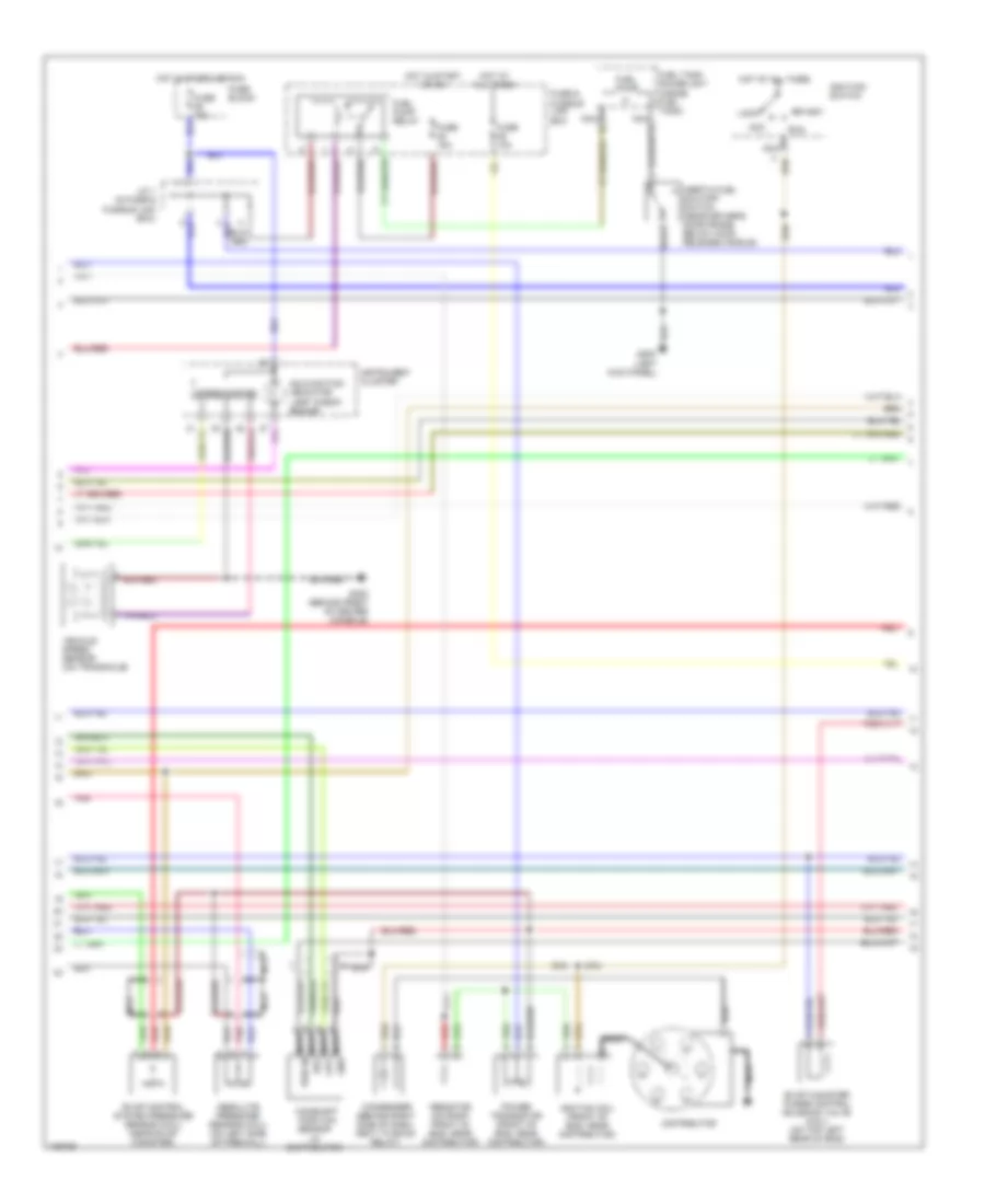
3.0L, Engine Performance Wiring Diagrams (1 of 3) for Nissan Quest XE 1998

List of elements for 3.0L, Engine Performance Wiring Diagrams (1 of 3) for Nissan Quest XE 1998:
- (between fuel tank & evap canister, on evap purge line) vacuum cut valve by-pass valve (cali)
- (on throttle body assembly)
- (right rear corner of eng compt, on power steering high pressure tube) power steering pressure (psp) switch
- (top left rear of eng) evap canister purge volume control valve (cali)
- A/c high pressure switch
- Air conditioning system (a/c relay)
- Assembly, integral to tp sensor)
- Compt, in air duct housing)
- Connector for switching diagnostic test modes without consult (left side of eng compt, near battery)
- Cooling fan relays
- Crankshaft position sensor (on transaxle housing, facing
- Eccs control module (ecm) (behind right side of dash)
- Eccs relay (behind right side of dash)
- Egr temperature (egrt) sensor (top right rear of eng, on base of egr valve)
- Engine coolant temperature (ect) sensor (front of eng,
- Flywheel teeth)
- Fuse & fusible link box
- Fuse 10a
- Fuse 47 10a
- Fuse 7.5a
- Fuse block
- G134 (top of engine)
- Hot at all times
- Hot in start
- Hot in start or on
- Instrument cluster system
- Intake air temperature (iat) sensor (left front of eng
- Nca
- Near distributor)
- Pnk
- Red
- Throttle position (tp) sensor
- Throttle position (tp) switch (on throttle body
- Transmission control module (tcm) (behind dash, right of steering column)
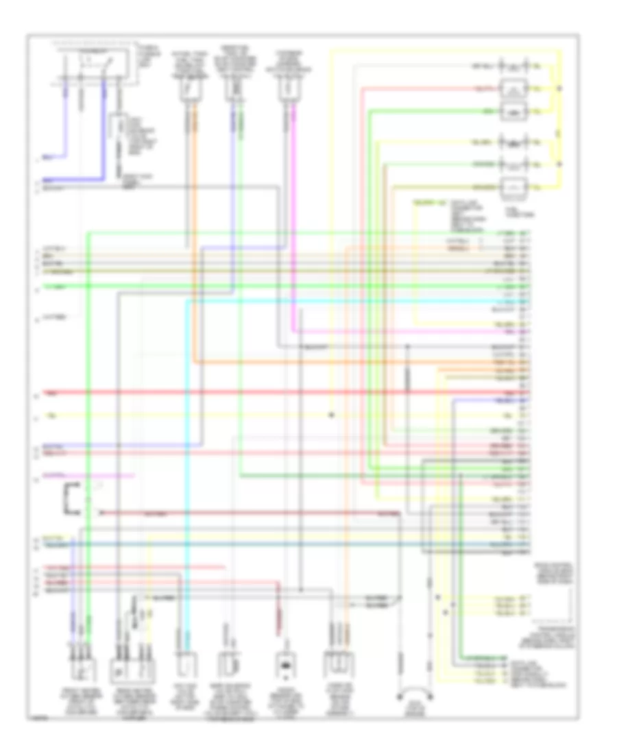
3.0L, Engine Performance Wiring Diagrams (2 of 3) for Nissan Quest XE 1998
List of elements for 3.0L, Engine Performance Wiring Diagrams (2 of 3) for Nissan Quest XE 1998:
- (left kick panel)
- Absolute pressure sensor (cali) (on left side of firewall)
- Acc
- Camshaft position
- Condenser (behind right side of dash, next to eccs relay)
- Distributor
- Evap canister purge control solenoid valve (cali) (on top left rear of eng)
- Evap control system pressure sensor (cali) (near evap canister)
- Fuel pump
- Fuel pump relay
- Fuel tank gauge unit (inside fuel tank)
- Fuse & fusible link box
- Fuse 10a
- Fuse 15a
- Fuse block
- G200
- G302 (behind front of center console)
- Hot at all times
- Hot in start or on
- Hot in start or run
- Ignitiion switch
- Ignition coil (front of eng, near distributor)
- Inertia fuel shutoff switch (near driver's door frame, below hood release handle)
- Instrument cluster
- J/c 1 (in fuse & fusible link box)
- Lock
- Malfunction indicator lamp "check engine"
- Nca
- Nca gnd
- Nca out
- Nca pwr in
- Nca ref
- Pnk
- Power transistor (front of eng, near distributor)
- Red
- Resistor (on right front of eng, near distributor)
- Run
- Sensor (in distributor)
- Speedometer
- Start
- Vehicle speed sensor (on transaxle)
3.0L, Engine Performance Wiring Diagrams (3 of 3) for Nissan Quest XE 1998
List of elements for 3.0L, Engine Performance Wiring Diagrams (3 of 3) for Nissan Quest XE 1998:
- (in fuel tank) fuel tank gauge unit (tank fuel temp sensor)
- (near fuel tank, on evap canister) evap canister vent control valve (cali)
- (right kick panel) g203
- (top rear of eng) map/baro switch solenoid valve (cali)
- Data link connector (for consult) (behind dash,
- Data link connector (gst) (behind dash next to fuse block)
- Eccs control module (ecm) (behind right side of dash)
- Egrc solenoid valve (cali) egr valve & evap canister purge control valve (except cali) (top rear of eng)
- Ficd relay
- Front heated oxygen sensor (front of catalytic converter)
- Fuel injectors
- Fuse & fusible link box
- G134 (top of engine)
- Iacv- ficd solenoid valve (top right front of eng)
- Iacv-aac valve (on top right side of eng)
- Knock sensor (ks) (top of eng, attached to cylinder clock)
- Mass air flow (maf) sensor (on air intake assembly)
- Nca
- Next to fuse block)
- Rear heated oxygen sensor (between rear catalytic converter & muffler)
- Red
- Transmission control module (behind dash, right of steering column)