ENGINE PERFORMANCE
2.4L VIN B
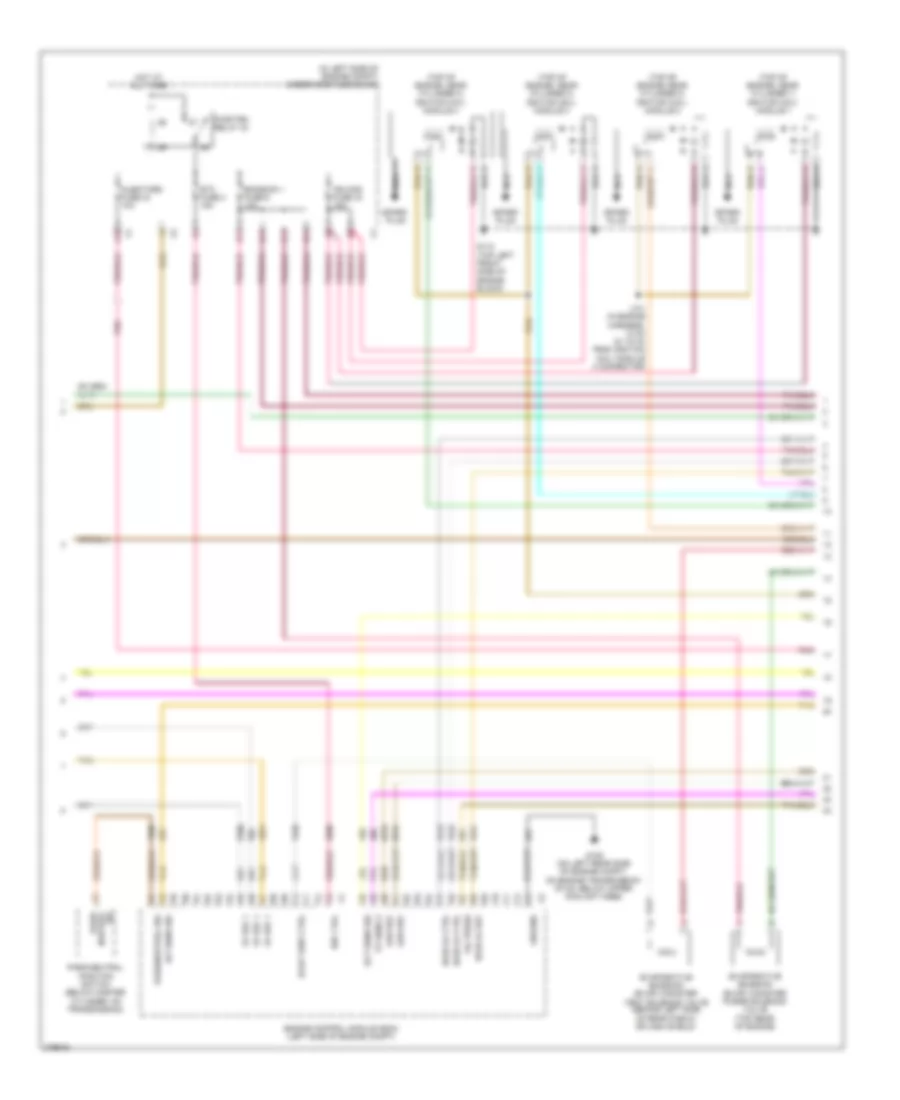
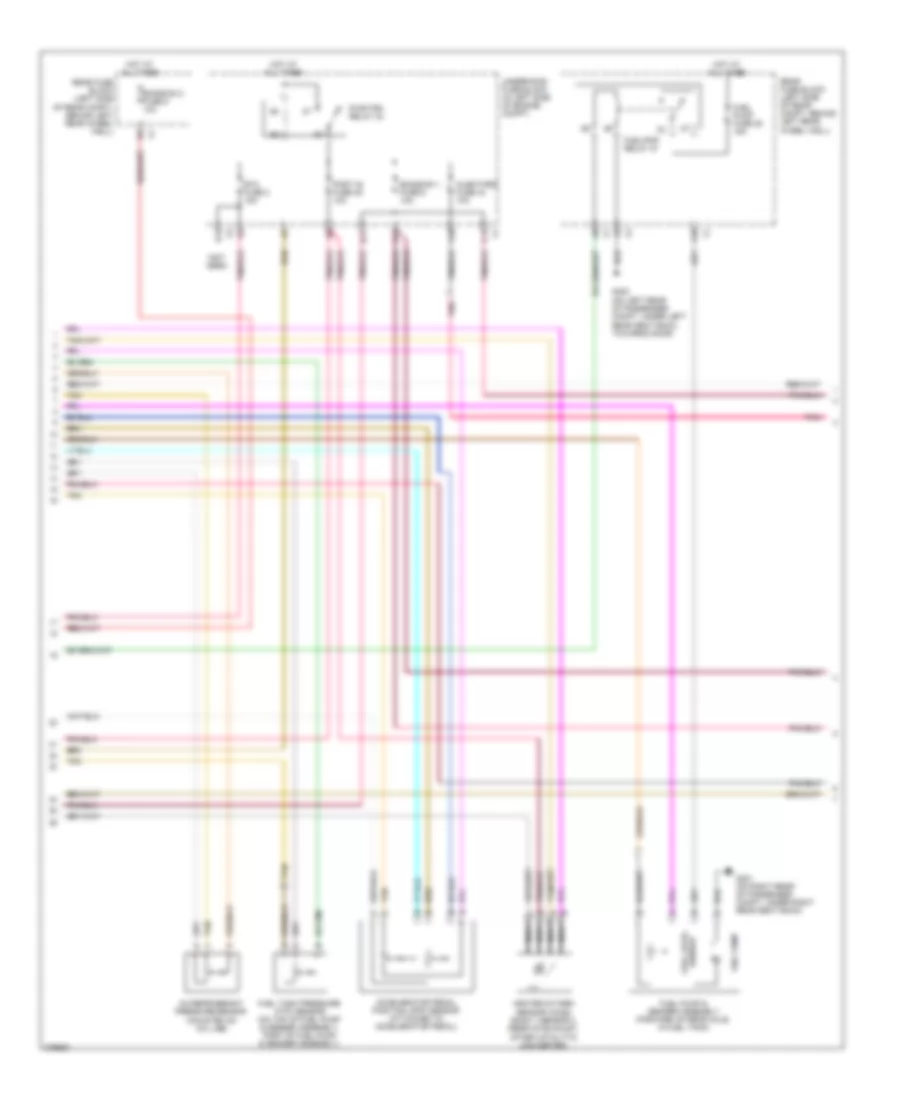
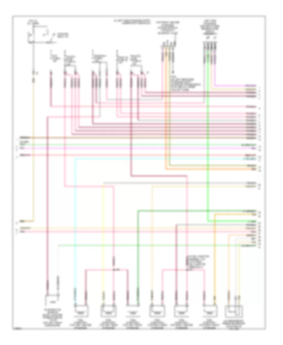
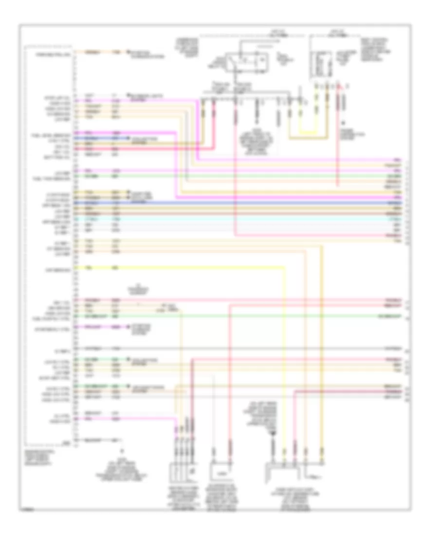
2.4L VIN B, Engine Performance Wiring Diagram (1 of 4) for Pontiac G6 GXP 2008

List of elements for 2.4L VIN B, Engine Performance Wiring Diagram (1 of 4) for Pontiac G6 GXP 2008:
- (in left side of engine compt) underhood fuse block
- 5v ref
- A/c refrigerant pressure sensor (mounted on a/c line)
- A/c rly ctrl
- A/c sens sig
- Acc vol
- Acc voltage
- Accelerator pedal position (app) sensor (attached to accelerator pedal)
- Air conditioning system
- App sens 1 sig
- App sens 2 sig
- Batt pos vol
- Body control module (bcm) (under right side of center console, near dash)
- C10
- Computer data lines system
- Cooling fans system
- Crank voltage
- Ecm fuse 13 10a
- Ecm ign 1 fuse 16 10a
- Engine control module (ecm) (left side of engine compt)
- Exterior lights system
- Fan rly ctrl
- Fuel level sens sig
- Fuel pump rly ctrl
- Fuel tank pressure (ftp) sensor (on top of fuel pump & sender assembly, part of fuel pump & sender assembly)
- Fuel tank sens sig
- G109 (left front of engine compt, on left rear side of core support, between g101 & g104)
- Gmlan data
- Hi gmlan data bus+
- Hi gmlan data bus-
- Hi rly ctrl
- Hot at all times
- Ign
- Ign 1 vol
- Instrument panel cluster (ipc)
- Logic
- Low ref
- Maf sens sig
- Malfun- ction indicator lamp
- Mil ctrl
- Pnk
- Pwr/trn rly ctrl
- Rly coil ctrl
- Run/ crank relay 32
- Starter rly ctrl
- Starting/ charging system
- Starting/charging system
- Stop lmp vol
- Tan
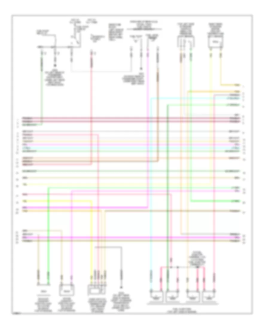
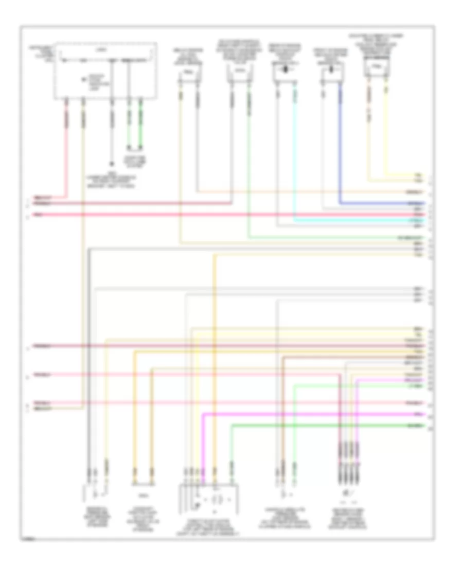
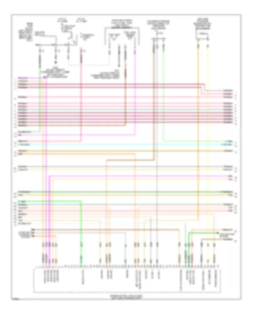
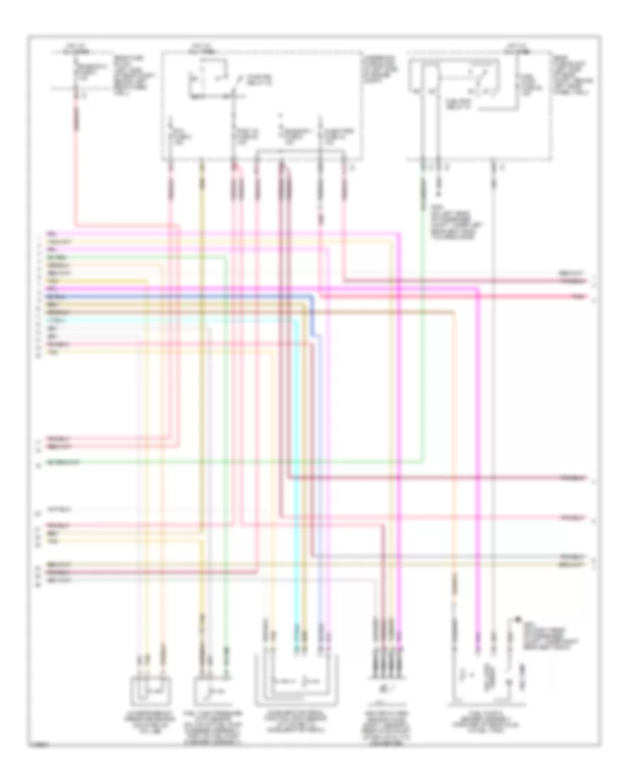
2.4L VIN B, Engine Performance Wiring Diagram (2 of 4) for Pontiac G6 GXP 2008
List of elements for 2.4L VIN B, Engine Performance Wiring Diagram (2 of 4) for Pontiac G6 GXP 2008:
- (in left side of engine compt) underhood fuse block
- (top of engine, near cylinder 1) ignition coil/ module 1
- (top of engine, near cylinder 2) ignition coil/ module 2
- (top of engine, near cylinder 3) ignition coil/ module 3
- (top of engine, near cylinder 4) ignition coil/ module 4
- 5v ref 1
- A10
- B11
- C11
- D11
- E11
- Ect sens sig
- Emission 1 fuse 6 10a
- Engine control module (ecm) (left side of engine compt)
- Etc fuse 2 15a
- Evap vent ctrl
- Evaporative emission (evap) canister purge solenoid valve (top rear of engine)
- Evaporative emission (evap) canister vent solenoid valve (behind left side of rear fascia splash shield)
- G105 (on left rear side of engine compt, on engine transmission stud, below upper coolant hose)
- G110 (top left front side of engine block)
- Ground
- Ho2s lo ctrl
- Ho2s lo ref
- Hot at all times
- Iat sens sig
- Ign 1 vol
- Ign mod fuse 43 15a
- Injectors fuse 44 10a
- J101 (in engine harness, 13 cm (5.118 in) from ignition coil/ module 4 connector)
- Low ref
- Nca
- Oil press
- Park/neutral position switch (below master cylinder, on transmission)
- Park/neutral sig
- Pnk
- Pwr/trn relay 33
- Sig neutral park/
- Spark plug
- Tan
- Tp sens 2
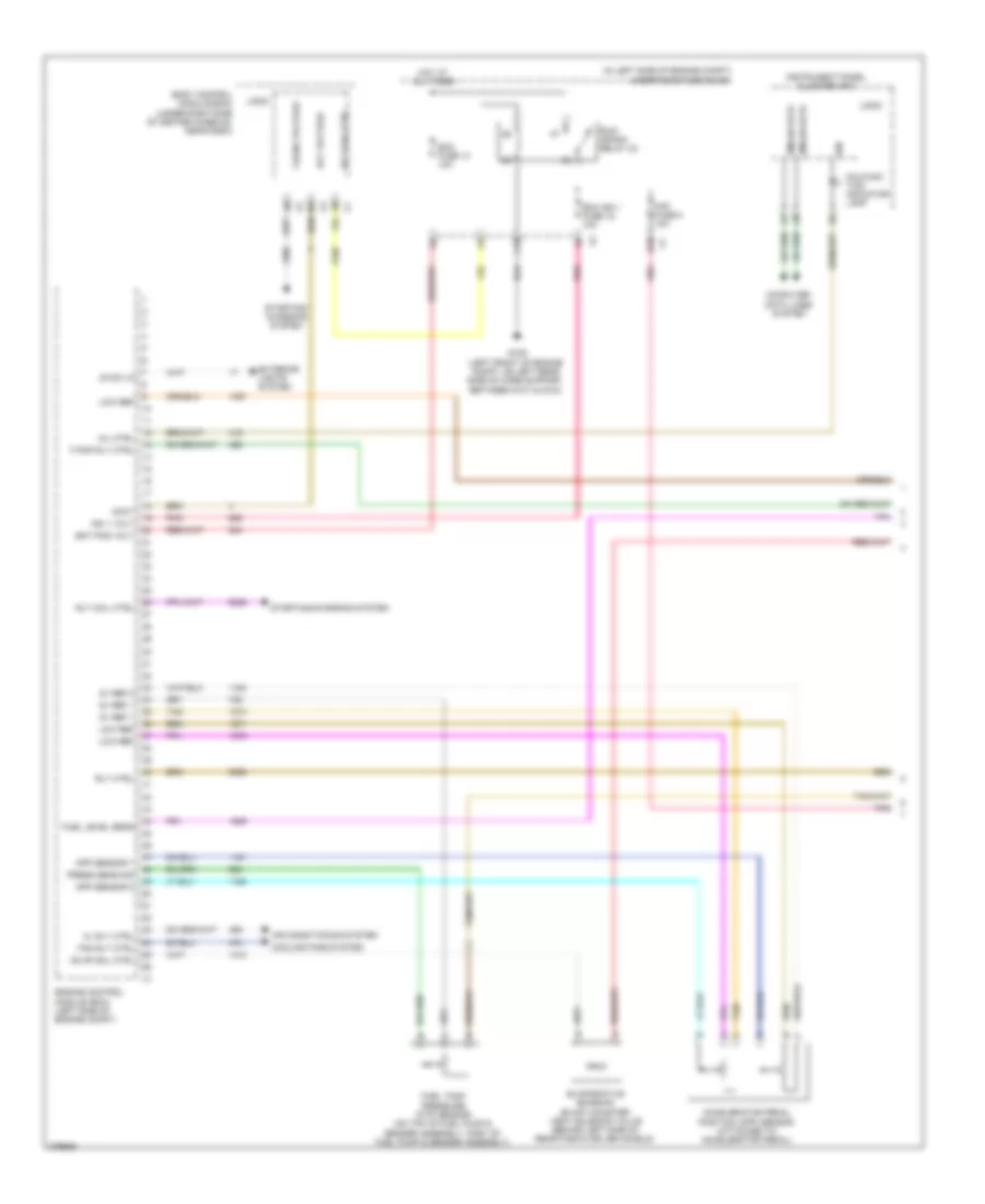
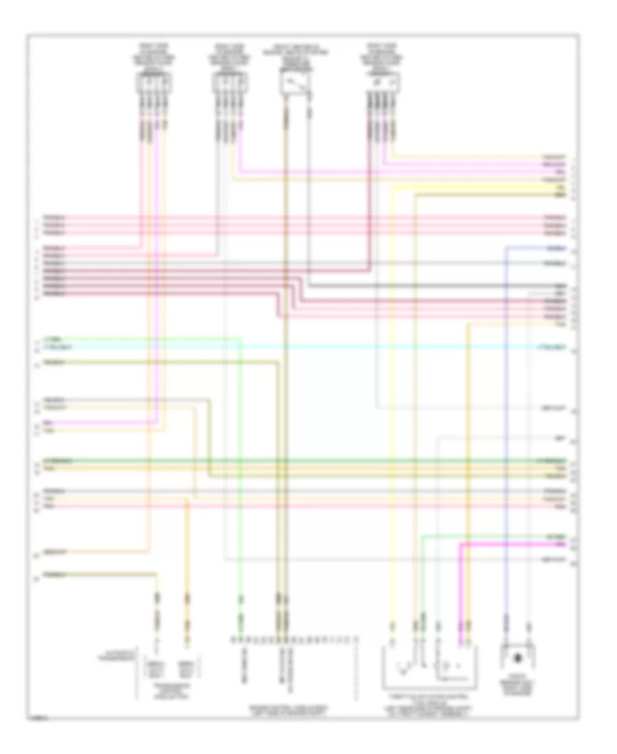
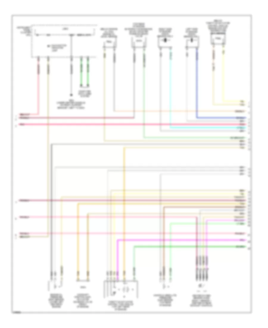
2.4L VIN B, Engine Performance Wiring Diagram (3 of 4) for Pontiac G6 GXP 2008
List of elements for 2.4L VIN B, Engine Performance Wiring Diagram (3 of 4) for Pontiac G6 GXP 2008:
- (forward of rear axle, in fuel tank) fuel pump & sender assembly
- (in fuel injector harness, 4 cm (1.6 in) from fuel injector 2 breakout) j130
- (right rear of engine) engine coolant temperature (ect) sensor
- (top left side of engine) manifold absolute pressure (map) sensor
- A10
- Emission 2 fuse 5 10a
- Exhaust camshaft position (cmp) actuator solenoid (top of engine)
- Fuel injectors (top left side of engine)
- Fuel level sensor
- Fuel pump
- Fuel pump fuse 25 15a
- Fuel/pump relay 37
- G105 (on left rear side of engine compt, on engine transmission stud, below upper coolant hose)
- G301 (on right rear of passenger compt, under right rear seat back)
- G302 (on left rear of passenger compartment, under left rear seat back, towards door)
- Hot at all times
- Intake camshaft position (cmp) actuator solenoid (top of engine)
- Mass air flow (maf)/intake air temperature (iat) sensor (left front of engine)
- Pnk
- Rear fuse block (left side of rear compt, behind left rear wheel well)
- Tan
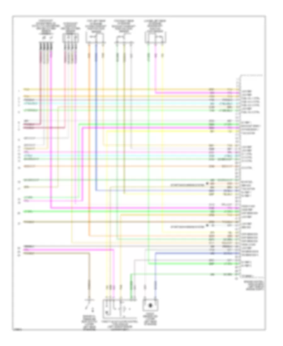
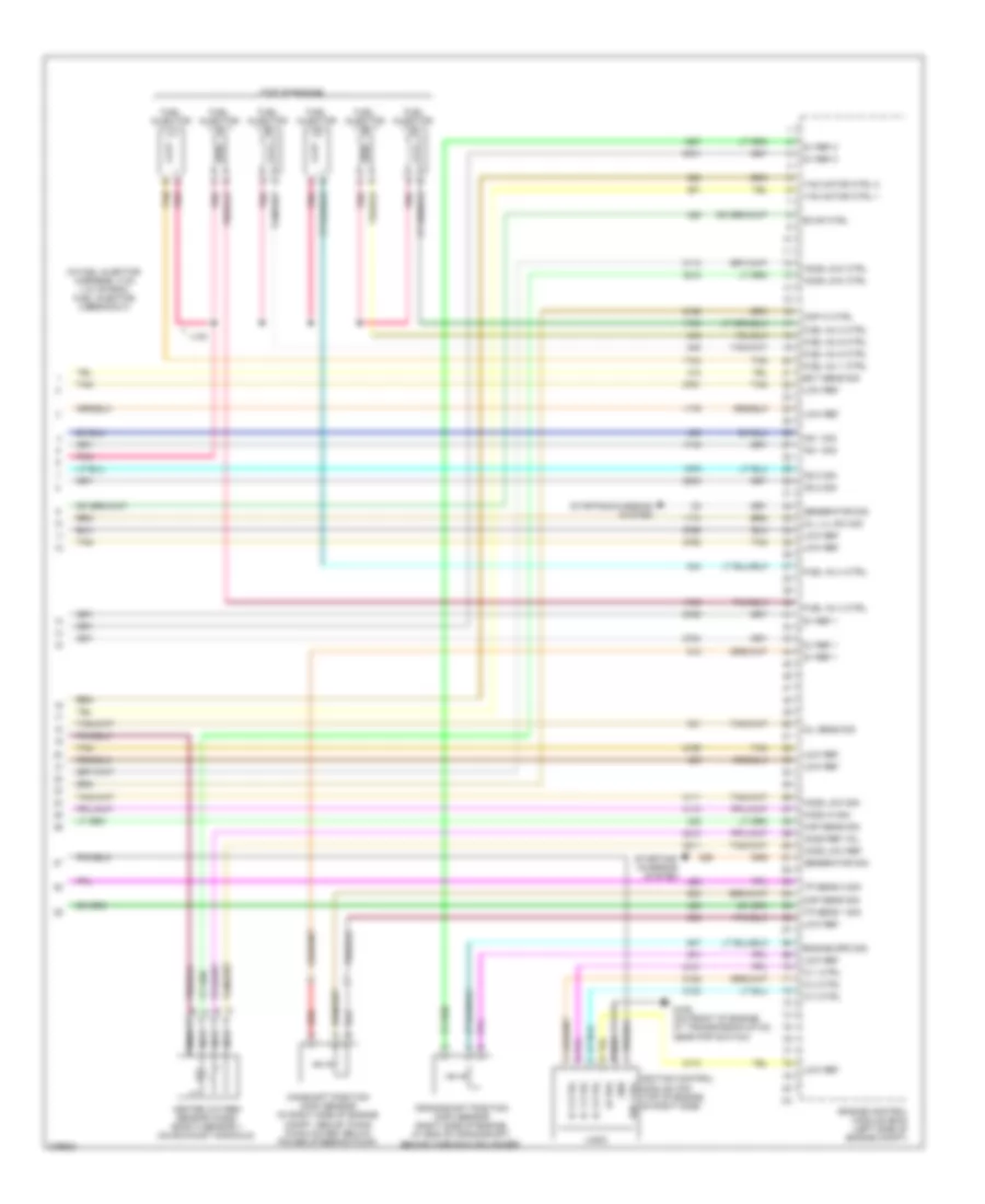
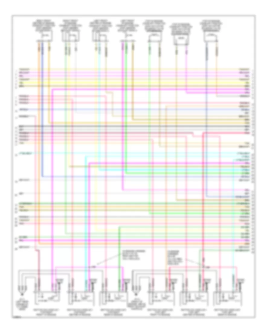
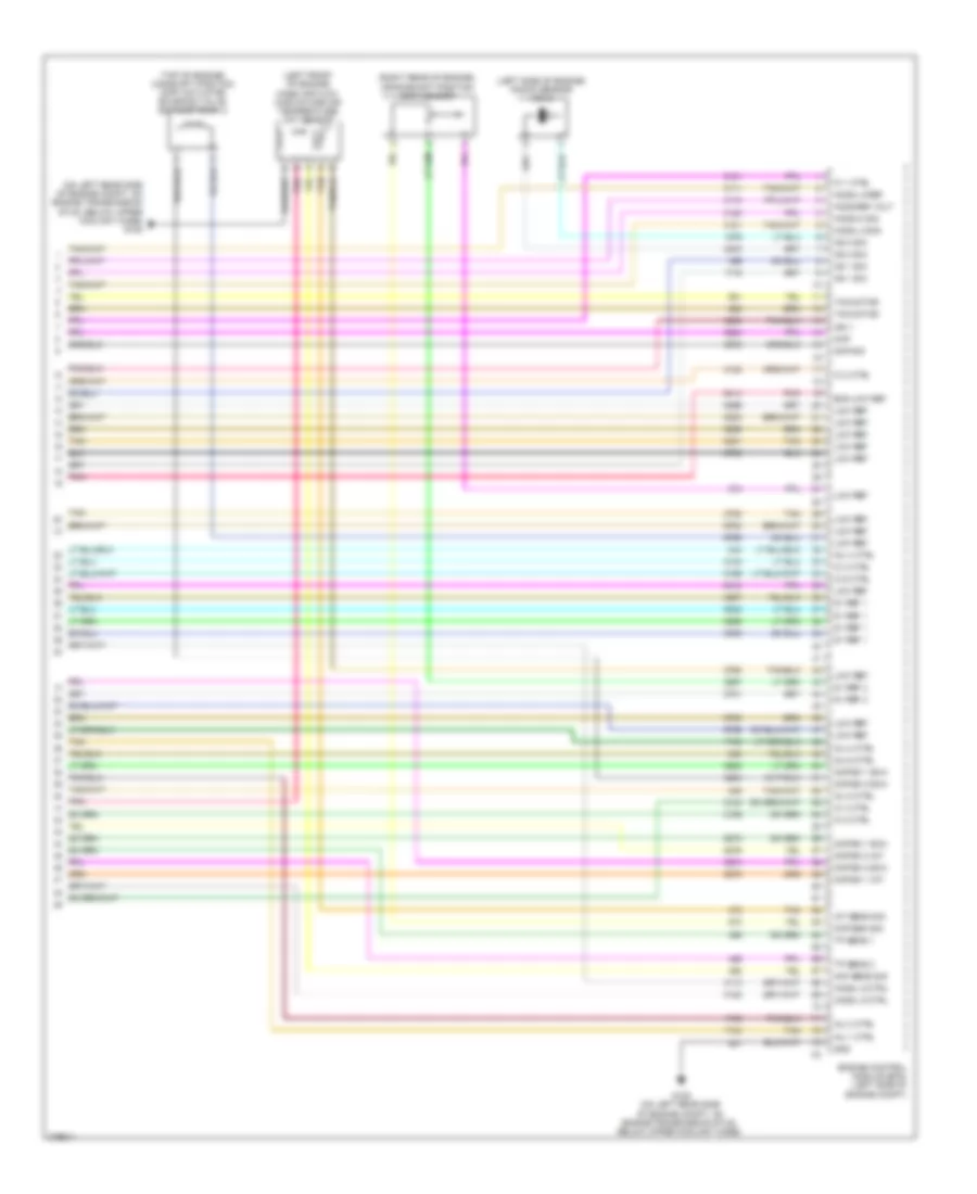
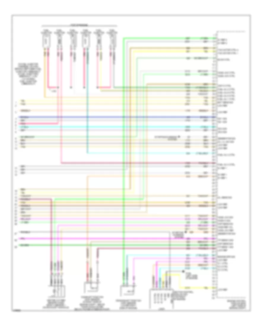
2.4L VIN B, Engine Performance Wiring Diagram (4 of 4) for Pontiac G6 GXP 2008
List of elements for 2.4L VIN B, Engine Performance Wiring Diagram (4 of 4) for Pontiac G6 GXP 2008:
- (in exhaust manifold) heated oxygen sensor (ho2s) 1
- (in exhaust, downstream of catalytic converter) heated oxygen sensor (ho2s) 2
- (lower left rear of engine) crankshaft position (ckp) sensor
- (top left rear of engine) intake camshaft position (cmp) sensor
- (top right rear of engine) exhaust camshaft position (cmp) sensor
- 5v ref 1
- 5v ref 2
- Ckp sens sig
- Cmp sens sig
- Engine control module (ecm) (left side of engine compt)
- Engine oil pressure (eop) switch (lower left rear of engine)
- Evap sol
- Exhaust bank 1
- Fuel inj 1 ctrl
- Fuel inj 2 ctrl
- Fuel inj 3 ctrl
- Fuel inj 4 ctrl
- Gen sig
- Ho2s hi sig
- Ho2s lo sig
- Ho2s ref
- Ic 1 ctrl
- Ic 2 ctrl
- Ic 3 ctrl
- Ic 4 ctrl
- Intake bank 1
- Knock sensor (ks) (lower left rear of engine)
- Ks sens sig a
- Ks sens sig b
- Low ref
- Map sens sig
- Nca
- Starting/charging system
- Tac motor
- Tan
- Throttle actuator control (tac) module (left side of engine compartment)
- Tp sens 1
3.5L VIN N
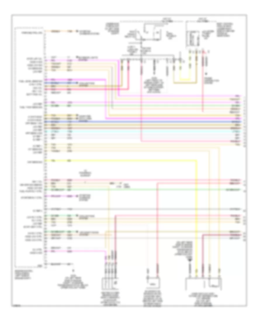
3.5L VIN N, Engine Performance Wiring Diagram (1 of 4) for Pontiac G6 GXP 2008
List of elements for 3.5L VIN N, Engine Performance Wiring Diagram (1 of 4) for Pontiac G6 GXP 2008:
- (not used)
- (on left rear side of engine compt, on engine transmission stud, below upper coolant hose) g105
- 5v ref 1
- 5v ref 2
- A/c rly ctrl
- A/c sens sig
- Acc vol
- Air conditioning system
- App sens 1 sig
- App sens 2 sig
- Batt pos vol
- Body control module (bcm) (under right side of center console, near dash)
- C10
- Cluster/ theft fuse 10a
- Computer data lines system
- Cooling fans system
- Ecm fuse 51 10a
- Engine control module (ecm) (left side of engine compt)
- Evap vent ctrl
- Evaporative emission (evap) canister vent solenoid valve (behind left side of rear fascia splash shield)
- Exterior lights system
- Fuel level sens sig
- Fuel pump rly ctrl
- Fuel tank sens sig
- G105 (on left rear side of engine compt, on engine transmission stud, below upper coolant hose)
- G109 (left front of engine compt, on left rear side of core support, between g101 & g104)
- Gnd
- Heated oxygen sensor (ho2s) bank 2 sensor 2 (in exhaust, after catalytic converter)
- Hi data bus+
- Hi data bus-
- Hi rly ctrl
- Ho2s hi sig
- Ho2s low ctrl
- Ho2s low sig
- Hot at all times
- Iat sens sig
- Ign 1 vol
- Ign 1/ ecm ign fuse 3 15a
- Ign mod fuse 43 15a
- Logic
- Low ref
- Low rly ctrl
- Maf sens sig
- Mass air flow (maf)/ intake air temperature (iat) sensor (on top left side of engine, at air cleaner)
- Mil ctrl
- Nca
- Park/neutral sig
- Pnk
- Power distribution system
- Rly ctrl
- Run/ crank relay 32
- Run/crank rly ctrl
- Starter rly ctrl
- Starting/ charging system
- Stop lmp vol
- Tan
- Underhood fuse block (in left side of engine compt)
- Veh spd sig (sedan)
- W/ panoramic sunroof
- X108
3.5L VIN N, Engine Performance Wiring Diagram (2 of 4) for Pontiac G6 GXP 2008
List of elements for 3.5L VIN N, Engine Performance Wiring Diagram (2 of 4) for Pontiac G6 GXP 2008:
- (not used)
- A/c refrigerant pressure sensor (mounted on a/c line)
- A10
- Accelerator pedal position (app) sensor (attached to accelerator pedal)
- B11
- C11
- D11
- D12
- Emission 1 fuse 6 10a
- Emission 2 fuse 5 10a
- Etc fuse 2 15a
- Fuel pump
- Fuel pump & sender assembly (forward of rear axle, in fuel tank)
- Fuel pump fuse 25 15a
- Fuel tank pressure (ftp) sensor (on top of fuel pump & sender assembly, part of fuel pump & sender assembly)
- Fuel/pmp relay 37
- G301 (on right rear of passenger compt, under right rear seat back)
- G302 (on left rear of passenger compt, under left rear seat back, towards door)
- Heated oxygen sensor (ho2s) bank 1 sensor 2 (rear of exhaust, after catalytic converter)
- Hot at all times
- Injectors fuse 44 10a
- Nca
- Pnk
- Post 02 fuse 45 10a
- Pwr/trn relay 33
- Rear fuse block (left side of rear compt, behind left rear wheel well)
- Sensor fuel level
- Tan
- Underhood fuse block (in left side of engine compt)
3.5L VIN N, Engine Performance Wiring Diagram (3 of 4) for Pontiac G6 GXP 2008
List of elements for 3.5L VIN N, Engine Performance Wiring Diagram (3 of 4) for Pontiac G6 GXP 2008:
- (below engine oil pan) engine oil level sensor
- (front of engine, above starter) knock sensor (ks) 1
- (mounted in rear cylinder head, below coolant reservoir) engine coolant temperature (ect) sensor
- (on intake manifold, near throttle body) evaporative emission (evap) canister purge solenoid valve
- (rear of engine, below exhaust manifold) knock sensor (ks) 2
- Camshaft position (cmp) actuator solenoid valve (front of engine)
- Computer data lines system
- Engine oil pressure (eop) sensor (left side of engine)
- G201 (under center console, on front support bracket, next to g203)
- Gnd
- Heated oxygen sensor (ho2s) bank 1 sensor 1 (center of rear exhaust manifold)
- Ign
- Instrument panel cluster (ipc)
- Logic
- Malfun- ction indicator lamp
- Manifold absolute pressure (map) sensor (on top rear of engine, in upper intake manifold)
- Nca
- Pnk
- Serial data
- Tan
- Throttle actuator control (tac) module (top left rear of engine compt, on throttle assembly)
3.5L VIN N, Engine Performance Wiring Diagram (4 of 4) for Pontiac G6 GXP 2008
List of elements for 3.5L VIN N, Engine Performance Wiring Diagram (4 of 4) for Pontiac G6 GXP 2008:
- (in fuel injector harness, 4 cm (1.6 in) from fuel injector 2 breakout)
- (top of engine)
- 5v ref 1
- 5v ref 2
- Camshaft position (cmp) sensor (in right side of engine compt, above timing chain cover, below power steering pump)
- Cmp hi ctrl
- Cmp sens sig
- Crankshaft position (ckp) sensor (right side of engine, at end of crankshaft, behind harmonic balancer)
- Ect sens sig
- Engine control module (ecm) (left side of engine compt)
- Engine spd sig
- Evap ctrl
- Fuel inj 1 ctrl
- Fuel inj 2 ctrl
- Fuel inj 3 ctrl
- Fuel inj 4 ctrl
- Fuel inj 5 ctrl
- Fuel inj 6 ctrl
- Fuel injector
- G106 (on front of engine, at transmission stud, near pnp switch)
- Generator sig
- Gnd
- Heated oxygen sensor (ho2s) bank 2 sensor 1 (on exhaust manifold)
- Ho2s hi sig
- Ho2s low ctrl
- Ho2s low ref
- Ho2s low sig
- Ho2s ref vol
- Ic 1 ctrl
- Ic 2 ctrl
- Ic 3 ctrl
- Ign 1 vol
- Ignition control module (icm) (top of engine, on right side)
- J130
- Ks 1 sig
- Ks 2 sig
- Lo ref
- Logic
- Low ref
- Map sens sig
- Nca
- Oil lvl sw sig
- Oil sens sig
- Pnk
- Red
- Starting/ charging system
- Starting/charging system
- Tac motor ctrl 1
- Tac motor ctrl 2
- Tan
- Tp sens 1 sig
- Tp sens 2 sig
3.6L VIN 7
3.6L VIN 7, Engine Performance Wiring Diagram (1 of 6) for Pontiac G6 GXP 2008
List of elements for 3.6L VIN 7, Engine Performance Wiring Diagram (1 of 6) for Pontiac G6 GXP 2008:
- (in left side of engine compt) underhood fuse block
- 5v ref 1
- 5v ref 2
- Acc voltage
- Accelerator pedal position (app) sensor (attached to accelerator pedal)
- Accy
- Air conditioning system
- App sensor 1
- App sensor 2
- B10
- Bat pos volt
- Body control module (bcm) (under right side of center console, near dash)
- C10
- Cl rly ctrl
- Computer data lines system
- Cooling fans system
- Crank voltage
- Ecm fuse 13 10a
- Ecm ign 1 fuse 16 10a
- Engine control module (ecm) (left side of engine compt)
- Evap sol ctrl
- Evaporative emission (evap) canister vent solenoid valve (behind left side of rear fascia splash shield)
- Exterior lights system
- F pmp rly ctrl
- Fan rly ctrl
- Fuel level sens
- Fuel tank pressure (ftp) sensor (on top of fuel pump & sender assembly, part of fuel pump & sender assembly)
- G109 (left front of engine compt, on left rear side of core support, between g101 & g104)
- Gmlan data
- Hot at all times
- Ign
- Ign 1 volt
- Instrument panel cluster (ipc)
- Logic
- Low ref
- Maf fuse 5 10a
- Malfunc- tion indicator lamp
- Mil ctrl
- Pnk
- Press sens sig
- Rly coil ctrl
- Rly ctrl
- Run/ crank relay 32
- Starting/ charging system
- Starting/charging system
- Stop lp
- Tan
3.6L VIN 7, Engine Performance Wiring Diagram (2 of 6) for Pontiac G6 GXP 2008
List of elements for 3.6L VIN 7, Engine Performance Wiring Diagram (2 of 6) for Pontiac G6 GXP 2008:
- (in left side of engine compt) underhood fuse block
- (left side of engine) heated oxygen sensor (ho2s) bank 2 sensor 1
- (top front center of engine) intake manifold tuning (imt) solenoid valve
- A/c refrigerant pressure sensor (mounted on a/c line)
- A10
- B11
- C11
- Ctrl c
- D11
- Emission 1 fuse 6 10a
- Etc fuse 2 15a
- Evaporative emission (evap) canister purge solenoid valve (top left front side engine)
- Fuel injector 1 (top right front of engine)
- Fuel injector 2 (top left front of engine)
- Fuel injector 3 (top right center of engine)
- Fuel injector 4 (top left center of engine)
- Fuel injector 5 (top right rear of engine)
- Fuel injector 6 (top left rear of engine)
- G105 (on left rear side of engine compt, on engine transmission stud, below upper coolant hose)
- Gnd b
- Hot at all times
- Ign a
- Inj/coil even fuse 44 15a
- Inj/coil odd fuse 43 15a
- J130
- J131
- Nca
- Pnk
- Post o2 fuse 45 10a
- Pwr/trn relay 33
- Sig d
- Tan
3.6L VIN 7, Engine Performance Wiring Diagram (3 of 6) for Pontiac G6 GXP 2008
List of elements for 3.6L VIN 7, Engine Performance Wiring Diagram (3 of 6) for Pontiac G6 GXP 2008:
- (forward of rear axle, in fuel tank) fuel pump & sender assembly
- (left side of engine) engine coolant temperature (ect) sensor
- (top rear of engine) manifold absolute pressure (map) sensor
- 5v ref 1
- A10
- Cooling fans system
- Ctrl actuator sig
- Ect sens sig
- Emission 2 fuse 5 10a
- Engine control module (ecm) (left side of engine compt)
- Evap sol
- Fan rly ctrl
- Fuel level sensor
- Fuel pump
- Fuel pump fuse 25 15a
- Fuel/pmp relay 37
- G301 (on right rear of passenger compt, under right rear seat back)
- G302 (on left rear of passenger compt, under left rear seat back, towards door)
- Gen on sig
- Gen sig
- Ho2s hi sig
- Ho2s lo ctrl
- Ho2s lo ref
- Ho2s lo sig
- Hot at all times
- Imt valve crtl
- Low ref
- Pnk
- Press sens sig
- Rear fuse block (left side of rear compt, behind left rear wheel well)
- Serial data bus +
- Serial data bus -
- Starting/ charging system
- Tan
3.6L VIN 7, Engine Performance Wiring Diagram (4 of 6) for Pontiac G6 GXP 2008
List of elements for 3.6L VIN 7, Engine Performance Wiring Diagram (4 of 6) for Pontiac G6 GXP 2008:
- (front center of engine, above starter) engine oil pressure (eop) switch
- (right side of engine) heated oxygen sensor (ho2s) bank 1 sensor 1
- (right side of engine) heated oxygen sensor (ho2s) bank 1 sensor 2
- (right side of engine) heated oxygen sensor (ho2s) bank 2 sensor 2
- Automatic transmission
- Engine control module (ecm) (left side of engine compt)
- Imt valve sig
- Knock sensor (ks) 1 (right side of engine)
- Map sens sig
- Nca
- Oil press sw sig
- Pnk
- Serial data bus +
- Serial data bus -
- Tan
- Throttle actuator control (tac) module (left rear side of engine compt, on throttle body assembly)
- Transmission control module (tcm)
3.6L VIN 7, Engine Performance Wiring Diagram (5 of 6) for Pontiac G6 GXP 2008
List of elements for 3.6L VIN 7, Engine Performance Wiring Diagram (5 of 6) for Pontiac G6 GXP 2008:
- (in engine harness, 20 cm (7.87 in) from ignition coil/ module 5)
- (in engine harness, 26.5 cm (10.4 in) from ignition coil/ module 6)
- (left front center of engine) camshaft position (cmp) sensor intake bank 2
- (left front of engine) camshaft position (cmp) sensor exhaust bank 2
- (right front center of engine) camshaft position (cmp) sensor intake bank 1
- (right front of engine) camshaft position (cmp) sensor exhaust bank 1
- (top of engine) camshaft position (cmp) actuator solenoid valve exhaust bank 1
- (top of engine) camshaft position (cmp) actuator solenoid valve intake bank 1
- (top of engine) camshaft position (cmp) actuator solenoid valve intake bank 2
- G111 (left rear corner of cylinder head)
- G113 (front of engine, above front exhaust manifold)
- Ignition coil/module 1 (top right front of engine)
- Ignition coil/module 2 (top left front of engine)
- Ignition coil/module 3 (top right center of engine)
- Ignition coil/module 4 (top left center of engine)
- Ignition coil/module 5 (top right rear of engine)
- Ignition coil/module 6 (top left rear of engine)
- J198
- J199
- Nca
- Pnk
- Pnk b
- Spark plug
- Tan
3.6L VIN 7, Engine Performance Wiring Diagram (6 of 6) for Pontiac G6 GXP 2008
List of elements for 3.6L VIN 7, Engine Performance Wiring Diagram (6 of 6) for Pontiac G6 GXP 2008:
- (left front of engine) mass air flow (maf)/intake air temperature (iat) sensor
- (left side of engine) knock sensor (ks) 2
- (on left rear side of engine compt, on engine transmission stud, below upper coolant hose) g105
- (right rear of engine) crankshaft position (ckp) sensor
- (top of engine) camshaft position (cmp) actuator solenoid valve exhaust bank 2
- 5v ref 1
- 5v ref 2
- Ckp sen sig
- Cmp
- Cmp bk 1 exh
- Cmp bk 1 int
- Cmp bk 2 exh
- Cmp bk 2 int
- Cmp sig
- Ecm low ref
- Engine control module (ecm) (left side of engine compt)
- G105 (on left rear side of engine compt, on engine transmission stud, below upper coolant hose)
- Gnd
- Ho2s hi sig
- Ho2s lo ctrl
- Ho2s lo ref
- Ho2s lo sig
- Ho2s ref volt
- Iat sens sig
- Ic 1 ctrl
- Ic 2 ctrl
- Ic 3 ctrl
- Ic 4 ctrl
- Ic 5 ctrl
- Ic 6 ctrl
- Ign 1
- Inj 1 ctrl
- Inj 2 ctrl
- Inj 3 ctrl
- Inj 4 ctrl
- Inj 5 ctrl
- Inj 6 ctrl
- Ks 1 sig
- Ks 2 sig
- Low ref
- Maf
- Maf sens sig
- Pnk
- Tac motor
- Tan
- Tp sens 1
- Tp sens 2
3.9L VIN 1
3.9L VIN 1, Engine Performance Wiring Diagram (1 of 4) for Pontiac G6 GXP 2008
List of elements for 3.9L VIN 1, Engine Performance Wiring Diagram (1 of 4) for Pontiac G6 GXP 2008:
- (on left rear side of engine compt, on engine transmission stud, below upper coolant hose) g105
- 5v ref 1
- 5v ref 2
- A/c rly ctrl
- A/c sens sig
- Acc vol
- Air conditioning system
- App sens 1 sig
- App sens 2 sig
- Batt pos vol
- Body control module (bcm) (under right side of center console, near dash)
- C10
- Cluster/ theft fuse 10a
- Computer data lines system
- Cooling fans system
- Ecm fuse 51 10a
- Ecm ign fuse 3 10a
- Engine control module (ecm) (left side of engine compt)
- Evap vent ctrl
- Evaporative emissions (evap) canister vent solenoid valve (behind left side of rear fascia splash shield)
- Exterior lights system
- Fuel level sens sig
- Fuel pump rly ctrl
- Fuel tank sens sig
- G105 (on left rear side of engine compt, on engine transmission stud, below upper coolant hose)
- G109 (left front of engine compt, on left rear side of core support, between g101 & g104)
- Gnd
- Heated oxygen sensor (ho2s) bank 2 sensor 2 (in exhaust, after catalytic converter)
- Hi data bus+
- Hi data bus-
- Hi rly ctrl
- Ho2s hi sig
- Ho2s low ctrl
- Ho2s low sig
- Hot at all times
- Iat sens sig
- Ign 1 vol
- Ign mod fuse 43 15a
- Logic
- Low ref
- Low rly ctrl
- Maf sens sig
- Mass air flow (maf)/ intake air temperature (iat) sensor (on top right side of engine, at air cleaner)
- Mil ctrl
- Nca
- P (not used) x108
- Park/neutral sig
- Pnk
- Power distribution system
- Rly ctrl
- Rly ctrl run/crank
- Run/ crank relay 32
- Starter rly ctrl
- Starting/ charging system
- Stop lmp vol
- Tan
- Underhood fuse block (in left side of engine compt)
- Veh spd sig
- W/ panoramic sunroof
3.9L VIN 1, Engine Performance Wiring Diagram (2 of 4) for Pontiac G6 GXP 2008
List of elements for 3.9L VIN 1, Engine Performance Wiring Diagram (2 of 4) for Pontiac G6 GXP 2008:
- A/c refrigerant pressure sensor (mounted on a/c line)
- A10
- Accelerator pedal position (app) sensor (attached to accelerator pedal)
- B11
- C11
- D11
- Emission 1 fuse 6 10a
- Emission 2 fuse 5 10a
- Etc fuse 2 15a
- Fuel pump
- Fuel pump & sender assembly (forward of rear axle, in fuel tank)
- Fuel pump fuse 25 15a
- Fuel tank pressure (ftp) sensor (on top of fuel pump & sender assembly, part of fuel pump & sender assembly)
- Fuel/pmp relay 37
- G301 (on right rear of passenger compt, under right rear seat back)
- G302 (on left rear of passenger compt, under left rear seat back, towards door)
- Heated oxygen sensor (ho2s) bank 1 sensor 2 (rear of exhaust, after catalytic converter)
- Hot at all times
- Injectors fuse 44 10a
- Nca
- Pnk
- Post 02 fuse 45 10a
- Pwr/trn relay 33
- Rear fuse block (left side of rear compt, behind left rear wheel well)
- Sensor fuel level
- Tan
- Underhood fuse block (in left side of engine compt)
3.9L VIN 1, Engine Performance Wiring Diagram (3 of 4) for Pontiac G6 GXP 2008
List of elements for 3.9L VIN 1, Engine Performance Wiring Diagram (3 of 4) for Pontiac G6 GXP 2008:
- (below engine oil pan) engine oil level sensor
- (below throttle actuator control module) engine coolant temperature (ect) sensor
- (left side of engine) knock sensor (ks) 1
- (right side of engine) knock sensor (ks) 2
- (top rear of engine) evaporative emissions (evap) canister purge solenoid valve
- Camshaft position (cmp) actuator solenoid valve (front of engine)
- Computer data lines system
- Engine oil pressure (eop) sensor (lower left center of engine)
- G201 (under center console, on front support bracket, next to g203)
- Gnd
- Heated oxygen sensor (ho2s) bank 1 sensor 1 (center of rear exhaust manifold)
- Ign
- Instrument panel cluster (ipc)
- Logic
- Malfunction indicator lamp
- Manifold absolute pressure (map) sensor (top rear of engine)
- Nca
- Pnk
- Serial data
- Tan
- Throttle actuator control (tac) module (top left rear of engine)
3.9L VIN 1, Engine Performance Wiring Diagram (4 of 4) for Pontiac G6 GXP 2008
List of elements for 3.9L VIN 1, Engine Performance Wiring Diagram (4 of 4) for Pontiac G6 GXP 2008:
- (in fuel injector harness, on main branch between fuel injector 3 breakout & fuel injector 2 breakout, 4 cm (1.6 in) from fuel injector 2 breakout)
- (top of engine)
- 5v ref 1
- 5v ref 2
- Camshaft position (cmp) sensor (in right side of engine compt, above timing chain cover, below power steering pump)
- Cmp hi ctrl
- Cmp sens sig
- Crankshaft position (ckp) sensor (lower right side of engine)
- Ect sens sig
- Engine control module (ecm) (left side of engine compt)
- Engine spd sig
- Evap ctrl
- Fuel inj 1 ctrl
- Fuel inj 2 ctrl
- Fuel inj 3 ctrl
- Fuel inj 4 ctrl
- Fuel inj 5 ctrl
- Fuel inj 6 ctrl
- Fuel injector
- G106 (left side of engine)
- Generator sig
- Gnd
- Heated oxygen sensor (ho2s) bank 2 sensor 1 (on exhaust manifold)
- Ho2s hi sig
- Ho2s low ctrl
- Ho2s low ref
- Ho2s low sig
- Ho2s ref vol
- Ic 1 ctrl
- Ic 2 ctrl
- Ic 3 ctrl
- Ign 1 vol
- Ignition control module (icm) (top right of engine)
- J130
- Ks 1 sig
- Ks 2 sig
- Lo ref
- Logic
- Low ref
- Map sens sig
- Nca
- Oil lvl sw sig
- Oil sens sig
- Pnk
- Red
- Starting/ charging system
- Starting/charging system
- Tac motor ctrl 1
- Tac motor ctrl 2
- Tan
- Tp sens 1 sig
- Tp sens 2 sig