ENGINE PERFORMANCE
3.8L VIN 2
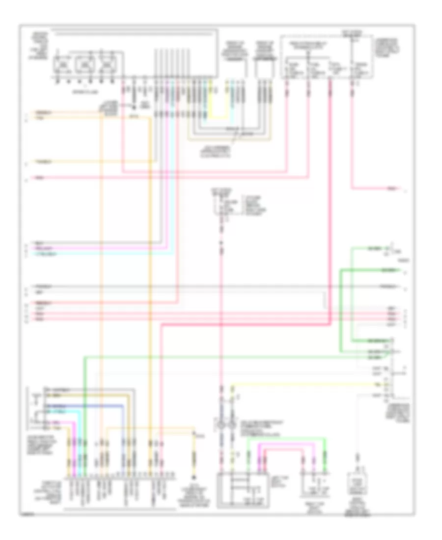
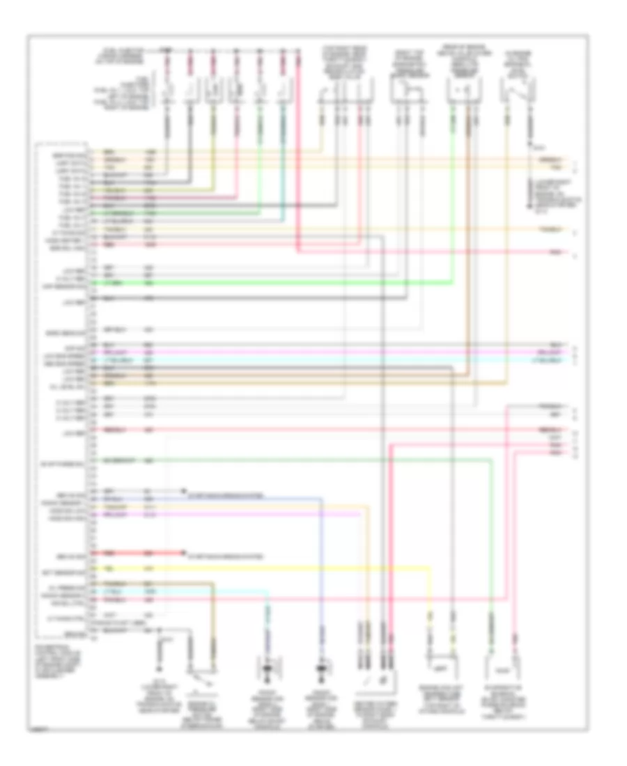
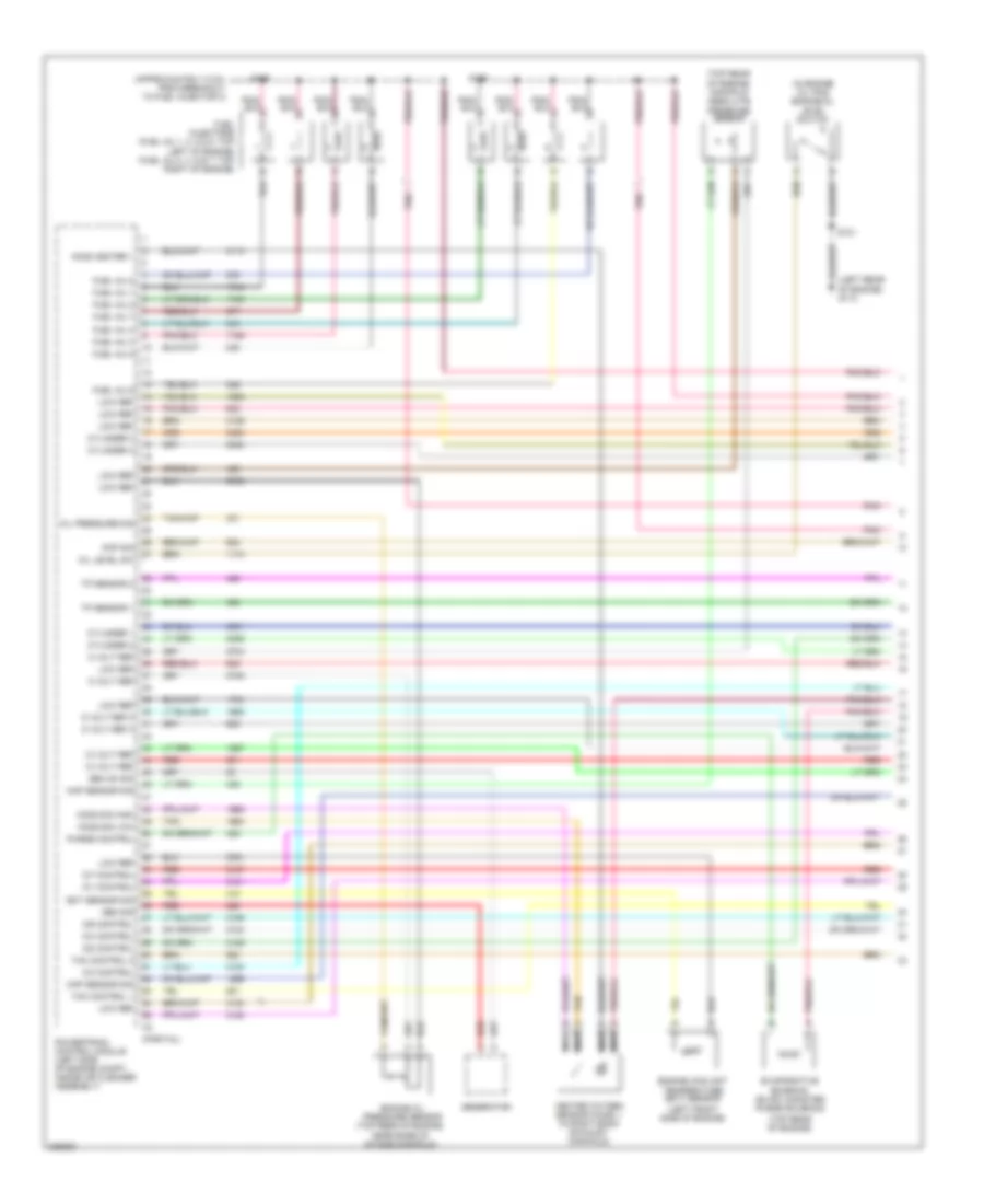
3.8L VIN 2, Engine Performance Wiring Diagram (1 of 5) for Pontiac Grand Prix GT 2006

List of elements for 3.8L VIN 2, Engine Performance Wiring Diagram (1 of 5) for Pontiac Grand Prix GT 2006:
- (fuel injector wiring harness, on top of engine)
- (in engine oil pan) engine oil level switch
- (lower right front of engine, on transaxle stud, near starter) g113
- (pins 62-72 not used)
- (top right of intake manifold)
- (top right rear of engine, near throttle body) exhaust gas recirculation (egr) valve
- (top right side of intake manifold) manifold absolute pressure sensor
- 5 volt ref
- Air sol ctrl
- Cmp sig
- Ect sensor sig
- Egr pos sig
- Egr sol high
- Engine coolant temperature (ect) sensor
- Engine oil pressure switch (below power steering pump)
- Evap purge sol
- Evaporative emission (evap) canister purge solenoid (below throttle body)
- Fuel inj 1
- Fuel inj 2
- Fuel inj 3
- Fuel inj 4
- Fuel inj 5
- Fuel inj 6
- Fuel injectors (fuel inj 1, 3 & 5: top left of engine) (fuel inj 2, 4 & 6: top right of engine)
- G113 (lower right front of engine, on transaxle stud, near starter)
- Gen on sig
- Ground
- Heated oxygen sensor (ho2s) 1 (in right bank exhaust manifold)
- Ho2s heater 1
- Ho2s sig high
- Ho2s sig low
- Ic timing ctrl
- Ic timing sig
- Knock sensor (ks) bank 1 (right side of engine, above starter)
- Knock sensor (ks) bank 2 (right side of engine, below exhst manifold)
- Knock sensor 1
- Knock sensor 2
- Low eng speed
- Low ref
- Map sensor sig
- Med eng speed
- Nca
- Oil level sw
- Oil press sig
- Pnk
- Powertrain control module (left front side of engine compt, in air cleaner assembly)
- Red
- S101
- S109
- Starting/charging system
- Tan
- Uart data
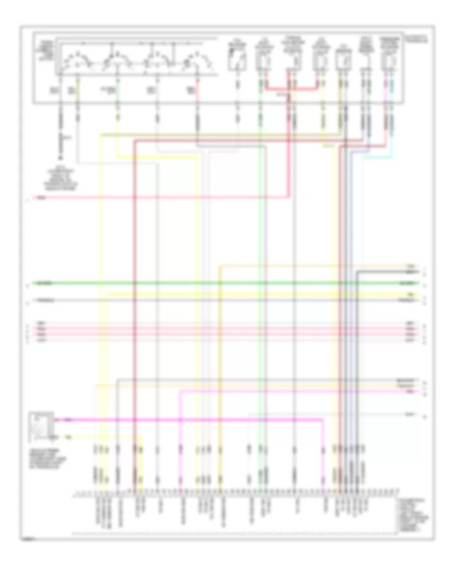
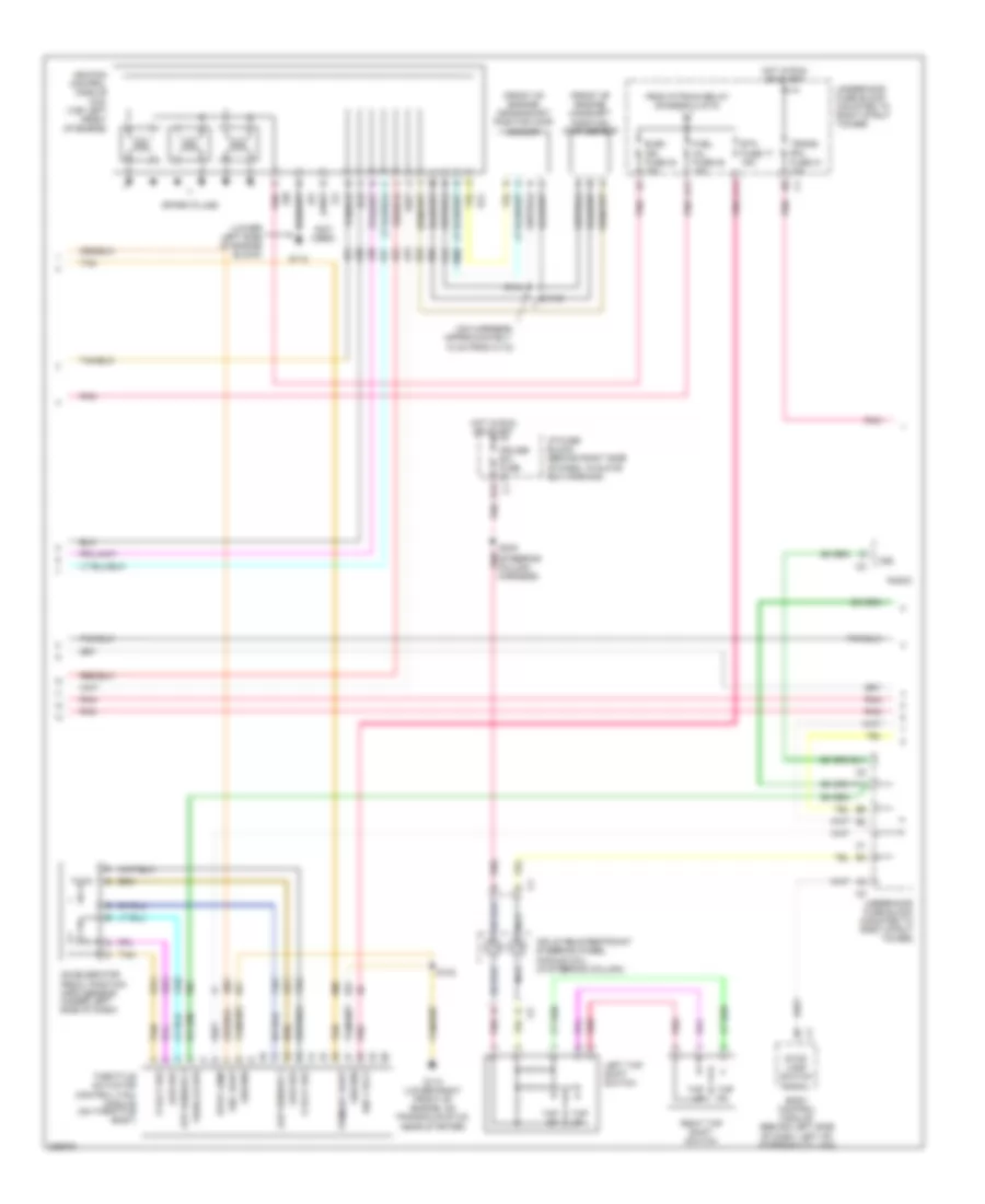
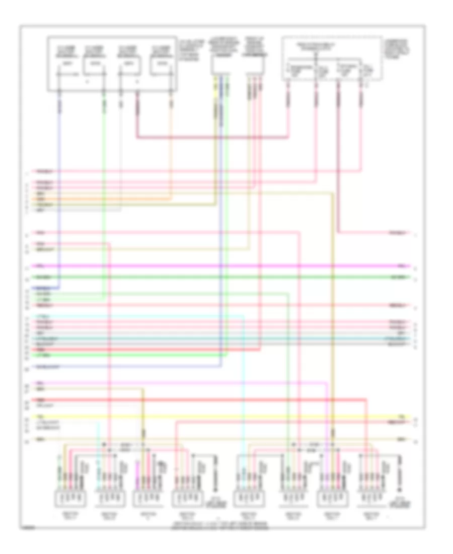
3.8L VIN 2, Engine Performance Wiring Diagram (2 of 5) for Pontiac Grand Prix GT 2006
List of elements for 3.8L VIN 2, Engine Performance Wiring Diagram (2 of 5) for Pontiac Grand Prix GT 2006:
- (front of engine) camshaft position (cmp) sensor
- (front of engine) crankshaft position (ckp) sensor
- (icm harness, approximately 12 cm from c110)
- (lower left side of engine block)
- (not used)
- 5 volt ref
- A11
- Aap sensor 1
- Accelerator pedal position (app) sensor (under left side of dash)
- App sensor 2
- B11
- Body control module (behind left side of dash)
- C11
- Cruise sw fuse 2a
- E12
- Elek ign fuse 24 15a
- Etc fuse 17 15a
- F11
- From p/train relay (diagram 4 of 5)
- Fuel inj fuse 20 15a
- G112
- G113 (lower right front of engine, on transaxle stud, near starter)
- Ground
- Hot in run or start
- I/p fuse block (behind right side of dash)
- Ign 1 volt
- Ignition control module (icm) (top left front of engine)
- Inflatable restraint steering wheel module coil (in steering column)
- Left tap shift switch
- Low ref
- Nca
- Pnk
- Primary uart
- Radio
- Right tap shift switch
- S102
- S144
- S145
- Sec uart
- Spark plugs
- Stop lamp
- Stop lamp switch signal
- Tan
- Tap dn
- Tap up
- Throttle actuator control (tac) module (on throttle body)
- Trans sol fuse 21 10a
- Underhood fuse block (mounted to right strut tower)
- Vehicle spd
- Vss
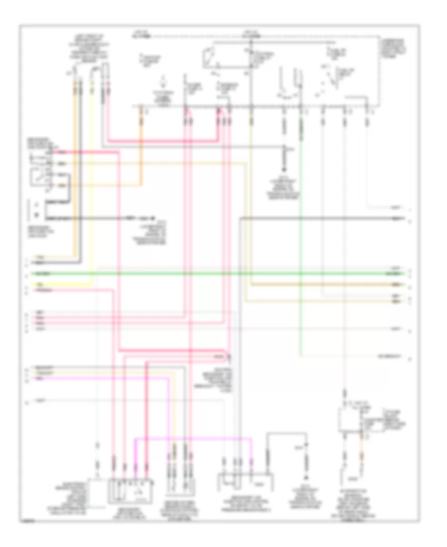
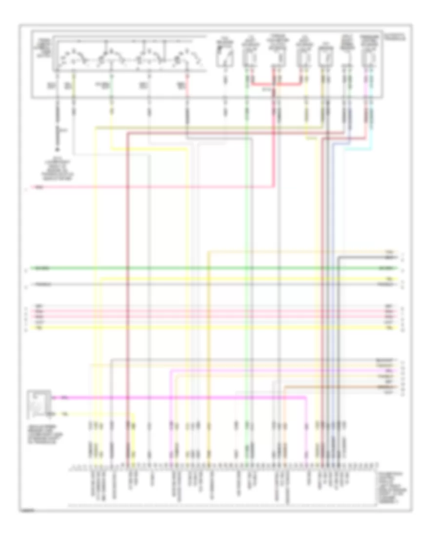
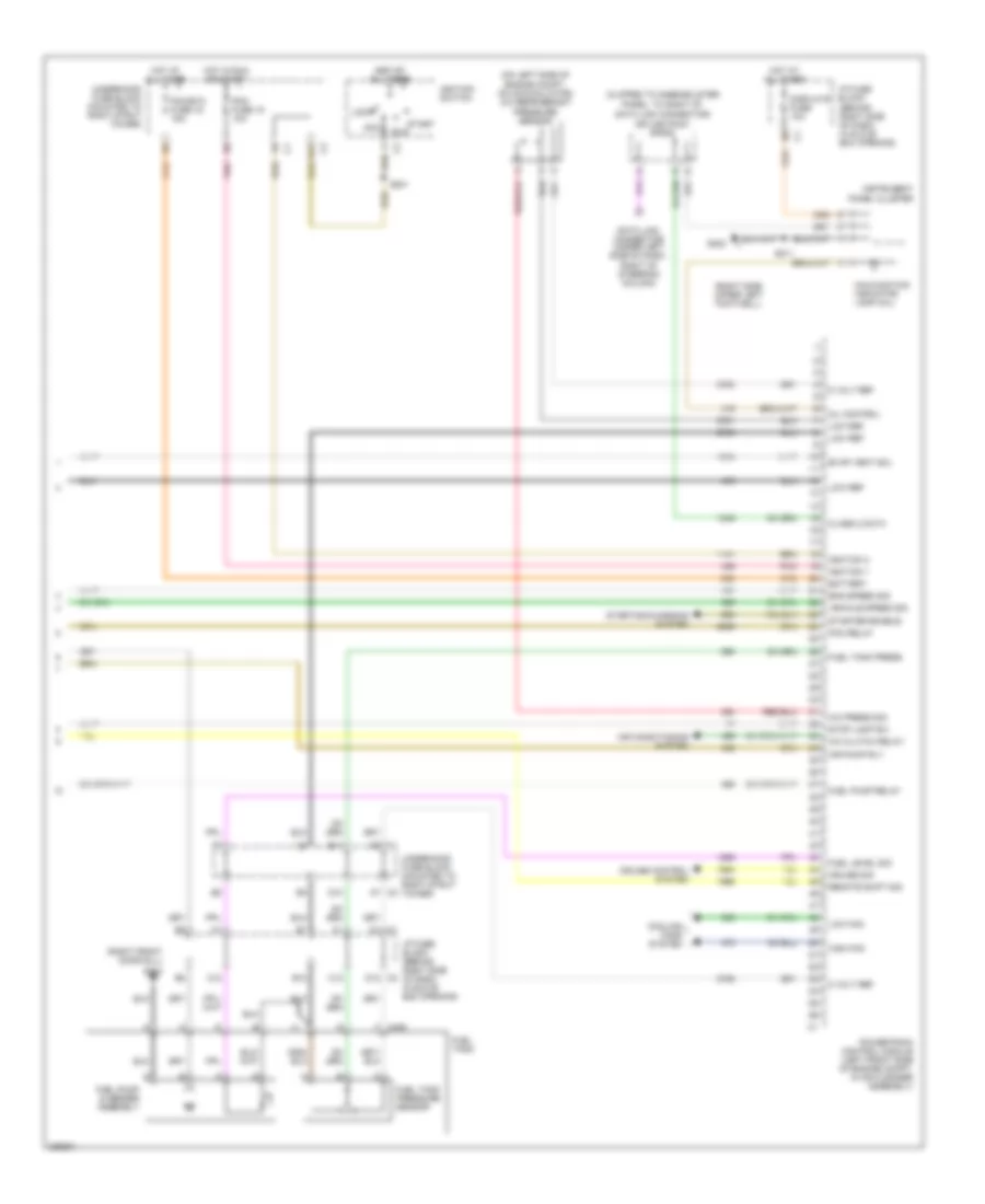
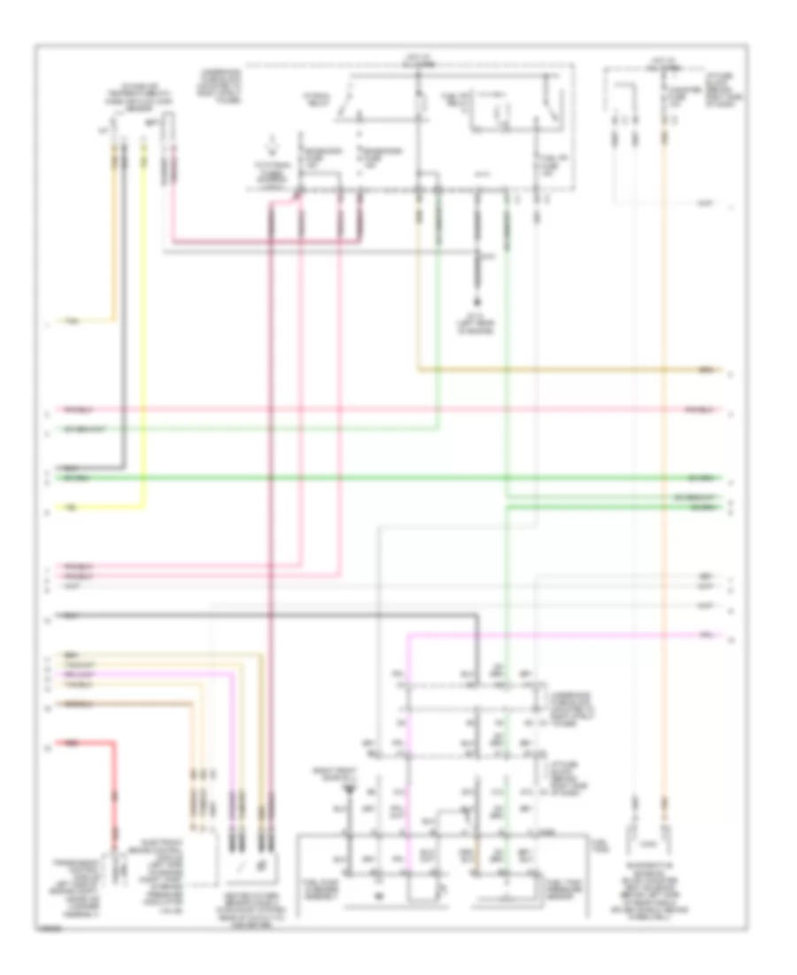
3.8L VIN 2, Engine Performance Wiring Diagram (3 of 5) for Pontiac Grand Prix GT 2006
List of elements for 3.8L VIN 2, Engine Performance Wiring Diagram (3 of 5) for Pontiac Grand Prix GT 2006:
- 1-2 shift solenoid valve
- 2-3 shift solenoid valve
- Air pres sen
- At iss sig
- Automatic transaxle
- G113 (lower right front of engine, on transaxle stud, near starter)
- Ho2s heater 2
- Ho2s sig high
- Ho2s sig low
- Iat sensor sig
- Input shaft speed sensor
- Low ref
- Maf sensor sig
- Pc sol
- Pnk
- Powertrain control module (left front side of engine compt, in air cleaner assembly)
- Pressure control solenoid valve
- Red
- S115
- Shift sol
- Tan
- Tcc release switch
- Tcc sol
- Tcc sw sig
- Tft sensor
- Tft sensor sig
- Torque converter clutch solenoid
- Tr sw a
- Tr sw b
- Tr sw c
- Tr sw p
- Trans- mission internal mode switch
- Vehicle speed sensor (vss) (lower right side of engine compt, on transaxle)
- Vss sig
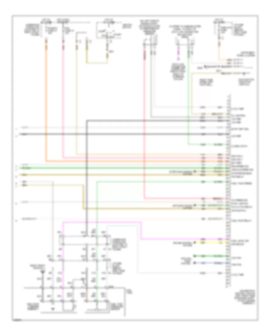
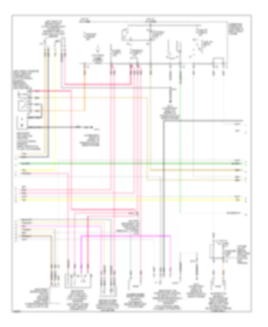
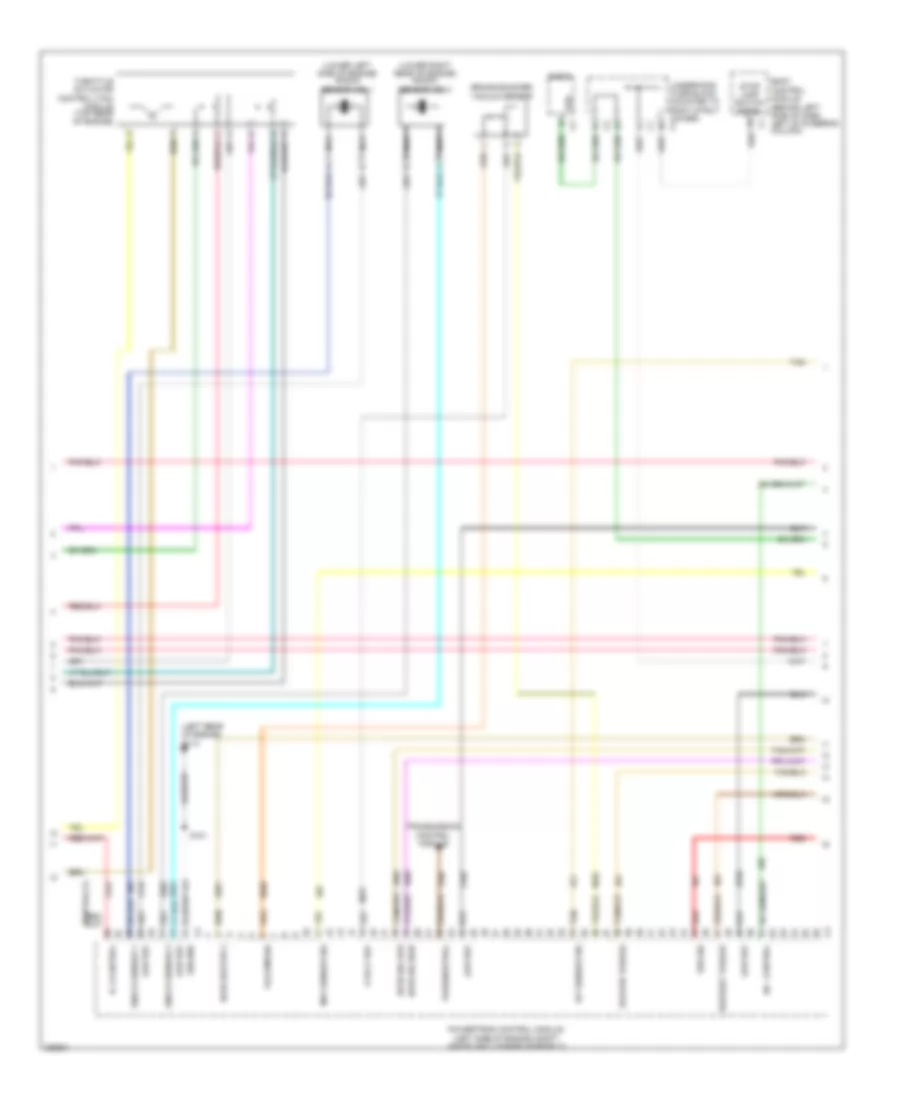
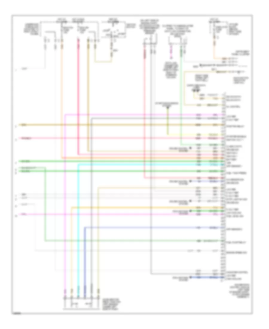
3.8L VIN 2, Engine Performance Wiring Diagram (4 of 5) for Pontiac Grand Prix GT 2006
List of elements for 3.8L VIN 2, Engine Performance Wiring Diagram (4 of 5) for Pontiac Grand Prix GT 2006:
- (left front of engine compt, in air cleaner duct) intake air temperature(iat)/ mass air flow (maf) sensor
- 5cm from secondary air injection (air) pump relay breakout, toward c1000)
- A nca
- Air pump fuse 56 50a
- B nca
- Canister fuse 10a
- D11
- Electronic brake control module (left side of engine compt, part of brake pressure modulator valve)
- Emission fuse 12 10a
- Evaporative emission (evap) canister vent solenoid (behind left side of rear fascia splash shield, behind wheelwell)
- F12
- Fuel pp fuse 22 15a
- Fuel pp relay
- G113 (lower right front of engine, on transaxle stud, near starter)
- Heated oxygen sensor (ho2s) 2 (in exhaust system, rear of catalytic converter)
- Hot at all times
- I/p fuse block (behind right side of dash)
- Iat
- Maf
- Nca
- O2 ssr fuse 14 15a
- P/train relay
- Pnk
- S101
- S103
- S104
- Secondary air injection (air) control solenoid valve/ pressure sensor bank 2
- Secondary air injection (air) pump
- Secondary air injection (air) pump relay
- Secondary air injection (air) valve relay
- Tan
- To p/train fuses (diagram 2 of 5)
- Underhood fuse block (mounted to right strut tower)
3.8L VIN 2, Engine Performance Wiring Diagram (5 of 5) for Pontiac Grand Prix GT 2006
List of elements for 3.8L VIN 2, Engine Performance Wiring Diagram (5 of 5) for Pontiac Grand Prix GT 2006:
- (clipped to knee-bolster panel, to right of data link connector)
- (on left side of engine compt, on accumulator) a/c refrigerant pressure sensor
- (right front door sill)
- (right side upper left footwell)
- 5 volt ref
- A/c clutch relay
- A/c press sig
- A12
- A7 c2
- Acc
- Air conditioning system
- Air pump rly
- B12
- Battery
- C1 d8
- C12
- Class 2 data
- Cooling fans system
- Cruise control system
- Cruise sig
- D1 c1
- D11
- D12 c2
- Data link connector (under left side of dash, right of steering column)
- Displays fuse 10a
- E11
- Eng speed sig
- Evap vent sol
- F c405
- Fuel level sig
- Fuel pump & sender assembly
- Fuel pump relay
- Fuel tank
- Fuel tank press
- Fuel tank pressure sensor
- G202
- G302
- High fan
- Hot at all times
- Hot in run or start
- I/p fuse block (behind right side of dash)
- Ignition 1
- Ignition 3
- Ignition switch
- Instrument panel cluster
- Lock
- Low fan
- Low ref
- Malfunction indicator lamp (mil)
- Mil control
- Pcm fuse 15 10a
- Pcm relay
- Pcm/etc fuse 16 15a
- Pnk
- Powertrain control module (left front side of engine compt, in air cleaner assembly)
- Run
- S201
- S211
- Splice pack sp205
- Start
- Starter enable
- Starting/charging system
- Stop lamp sw
- Underhood fuse block (mounted to right strut tower)
- Vehicle speed sig
3.8L VIN 4
3.8L VIN 4, Engine Performance Wiring Diagram (1 of 5) for Pontiac Grand Prix GT 2006
List of elements for 3.8L VIN 4, Engine Performance Wiring Diagram (1 of 5) for Pontiac Grand Prix GT 2006:
- (fuel injector wiring harness, on top of engine)
- (in engine oil pan) engine oil level switch
- (lower right front of engine, on transaxle stud, near starter) g113
- (pins 62-72 not used)
- (rear of engine, above valve cover) manifold absolute pressure sensor
- (right top of engine)
- (top right of intake manifold)
- (top right rear of engine, near throttle body) exhaust gas recirculation (egr) valve
- 5 volt ref
- Air sol ctrl
- Baro sens sig
- Barometric pressure (baro) sensor
- Cmp sig
- Ect sensor sig
- Egr pos sig
- Egr sol high
- Engine coolant temperature (ect) sensor
- Engine oil pressure switch (below power steering pump)
- Evap purge sol
- Evaporative emission (evap) canister purge solenoid (below throttle body)
- Fuel inj 1
- Fuel inj 2
- Fuel inj 3
- Fuel inj 4
- Fuel inj 5
- Fuel inj 6
- Fuel injectors (fuel inj 1, 3 & 5: top left of engine) (fuel inj 2, 4 & 6: top right of engine)
- G113 (lower right front of engine, on transaxle stud, near starter)
- Gen on sig
- Ground
- Heated oxygen sensor (ho2s) 1 (in right bank exhaust manifold)
- Ho2s heater 1
- Ho2s sig high
- Ho2s sig low
- Ic timing ctrl
- Ic timing sig
- Knock sensor (ks) bank 1 (right side of engine, above starter)
- Knock sensor (ks) bank 2 (right side of engine, below exhst manifold)
- Knock sensor 1
- Knock sensor 2
- Low eng speed
- Low ref
- Map sensor sig
- Med eng speed
- Nca
- Oil level sw
- Oil press sig
- Pnk
- Powertrain control module (left front side of engine compt, in air cleaner assembly)
- Red
- S101
- S109
- Starting/charging system
- Tan
- Uart data
3.8L VIN 4, Engine Performance Wiring Diagram (2 of 5) for Pontiac Grand Prix GT 2006
List of elements for 3.8L VIN 4, Engine Performance Wiring Diagram (2 of 5) for Pontiac Grand Prix GT 2006:
- (front of engine) camshaft position (cmp) sensor
- (front of engine) crankshaft position (ckp) sensor
- (icm harness, approximately 12 cm from c110)
- (lower left side of engine block)
- (not used)
- (steering column pnk harness)
- 5 volt ref
- A11
- Aap sensor 1
- Accelerator pedal position (app) sensor (under left side of dash)
- App sensor 2
- B11
- Body control module (behind left side of dash, left of) steering column)
- C11
- Cruise sw fuse 2a
- E12
- Elek ign fuse 24 15a
- Etc fuse 17 15a
- F11
- From p/train relay (diagram 4 of 5)
- Fuel inj fuse 20 15a
- G112
- G113 (lower right front of engine, on transaxle stud, near starter)
- Ground
- Hot in run or start
- I/p fuse block (behind right side of dash, in glove box opening)
- Ign 1 volt
- Ignition control module (icm) (top left front of engine)
- Inflatable restraint steering wheel module coil (in steering column)
- Left tap shift switch
- Low ref
- Nca
- Pnk
- Primary uart
- Radio
- Right tap shift switch
- S102
- S144
- S145
- S240
- Sec uart
- Spark plugs
- Stop lamp
- Stop lamp switch signal
- Tan
- Tap dn
- Tap up
- Throttle actuator control (tac) module (on throttle body)
- Trans sol fuse 21 10a
- Underhood fuse block (mounted to right strut tower)
- Vehicle spd
- Vss
3.8L VIN 4, Engine Performance Wiring Diagram (3 of 5) for Pontiac Grand Prix GT 2006
List of elements for 3.8L VIN 4, Engine Performance Wiring Diagram (3 of 5) for Pontiac Grand Prix GT 2006:
- 1-2 shift solenoid valve
- 2-3 shift solenoid valve
- Air pres sen
- At iss sig
- Automatic transaxle
- Boost control
- Deliver torque
- G113 (lower right front of engine, on transaxle stud, near starter)
- Ho2s heater 2
- Ho2s sig high
- Ho2s sig low
- Iat sensor sig
- Input shaft speed sensor
- Low ref
- Maf sensor sig
- Pc sol
- Pnk
- Powertrain control module (left front side of engine compt, in air cleaner assembly)
- Pressure control solenoid valve
- Red
- Request torque
- S115
- Shift sol
- Tan
- Tcc release switch
- Tcc sol
- Tcc sw sig
- Tft sensor
- Tft sensor sig
- Torque converter clutch solenoid
- Tr sw a
- Tr sw b
- Tr sw c
- Tr sw p
- Trans- mission internal mode switch
- Vehicle speed sensor (vss) (lower right side of engine compt, on transaxle)
- Vss sig
3.8L VIN 4, Engine Performance Wiring Diagram (4 of 5) for Pontiac Grand Prix GT 2006
List of elements for 3.8L VIN 4, Engine Performance Wiring Diagram (4 of 5) for Pontiac Grand Prix GT 2006:
- (left front of eng
- (left front of engine compt near air cleaner duct) (with california
- (left front of engine compt, in air cleaner duct) intake air temperature(iat)/ mass air flow (maf) sensor
- (lower right front of engine, on transaxle stud, near starter)
- (near trans stud, to left of starter)
- (top of engine, near
- (top rear of engine, above left valve cover)
- (with california
- (with california emission)
- 5cm from secondary air injection (air) pump relay breakout, toward c100)
- A nca
- Air pump fuse 56 50a
- B nca
- Canister fuse 10a
- Compt near air cleaner duct)
- Cylinder 4 intake port)
- D11
- Electronic brake control module (left side of engine compt, part of brake pressure modulator valve)
- Emission fuse 12 10a
- Emission)
- Emission) secondary air injection (air) pump relay
- Evaporative emission (evap) canister vent solenoid (behind left side of rear fascia splash shield, behind wheelwell)
- F12
- Fuel pp fuse 22 15a
- Fuel pp relay
- G113
- G113 (lower right front of engine, on transaxle stud, near starter)
- Heated oxygen sensor (ho2s) 2 (in exhaust system, rear of catalytic converter)
- Hot at all times
- I/p fuse block (behind right side of dash, in glove box opening)
- Iat
- Maf
- Nca
- O2 ssr fuse 14 15a
- P/train relay
- Pnk
- S101
- S103
- S104
- Secondary air injection (air) control solenoid valve/ pressure sensor bank 2
- Secondary air injection (air) pump
- Secondary air injection (air) valve relay
- Supercharger boost control solenoid
- Tan
- To p/train fuses (diagram 2 of 5)
- Underhood fuse block (mounted to right strut tower)
3.8L VIN 4, Engine Performance Wiring Diagram (5 of 5) for Pontiac Grand Prix GT 2006
List of elements for 3.8L VIN 4, Engine Performance Wiring Diagram (5 of 5) for Pontiac Grand Prix GT 2006:
- (clipped to knee-bolster panel, to right of data link connector)
- (on left side of engine compt, on accumulator) a/c refrigerant pressure sensor
- (right front door sill)
- (right side upper left footwell)
- 5 volt ref
- A/c clutch relay
- A/c press sig
- A12
- A7 c2
- Acc
- Air conditioning system
- Air pump rly
- B12
- Battery
- C1 d8
- C12
- Class 2 data
- Cooling fans system
- Cruise control system
- Cruise sig
- D1 c1
- D10
- D11
- D12 c2
- Data link connector (under left side of dash, right of steering column)
- Displays fuse 10a
- E11
- Eng speed sig
- Evap vent sol
- F c405
- Fuel level sig
- Fuel pump & sender assembly
- Fuel pump relay
- Fuel tank
- Fuel tank press
- Fuel tank pressure sensor
- G202
- G302
- High fan
- Hot at all times
- Hot at hot at all times all times
- Hot in run or start
- I/p fuse block (behind right side of dash, in glove box opening)
- Ignition 1
- Ignition 3
- Ignition switch
- Instrument panel cluster
- Lock
- Low fan
- Low ref
- Malfunction indicator lamp (mil)
- Mil control
- Pcm fuse 15 10a
- Pcm relay
- Pcm/etc fuse 16 15a
- Pnk
- Powertrain control module (left front side of engine compt, in air cleaner assembly)
- Remote shift sig
- Run
- S201
- S211
- Splice pack sp205
- Start
- Starter enable
- Starting/charging system
- Stop lamp sw
- Underhood fuse block (mounted to right strut tower)
- Vehicle speed sig
5.3L VIN C
5.3L VIN C, Engine Performance Wiring Diagram (1 of 5) for Pontiac Grand Prix GT 2006
List of elements for 5.3L VIN C, Engine Performance Wiring Diagram (1 of 5) for Pontiac Grand Prix GT 2006:
- (approximately 5 cm from breakout to fuel injector 3)
- (in engine oil pan) engine oil level switch
- (left front side of engine)
- (left rear of engine) g113
- (partial)
- (top rear of engine)
- (top rear of engine) manifold absolute pressure sensor
- 12 volt ref
- 5 volt ref
- 5 volt ref 2
- Ckp sensor sig
- Cmp sig
- Cylinder 1
- Cylinder 2
- Cylinder 3
- Cylinder 4
- Ect sensor sig
- Engine coolant temperature (ect) sensor
- Engine oil pressure sensor (top rear of engine, near base of intake manifold)
- Evaporative emission (evap) canister purge solenoid
- Fuel inj 1
- Fuel inj 2
- Fuel inj 3
- Fuel inj 4
- Fuel inj 5
- Fuel inj 6
- Fuel inj 7
- Fuel inj 8
- Fuel injectors (fuel inj 1, 3, 5 & 8: top left of engine) (fuel inj 2, 4, 6 & 7: top right of engine)
- Gen on sig
- Gen sig
- Generator
- Heated oxygen sensor (ho2s) 1 (in right bank exhaust manifold)
- Ho2s heater 1
- Ho2s sig high
- Ho2s sig low
- Ic1 control
- Ic3 control
- Ic4 control
- Ic5 control
- Ic6 control
- Ic7 control
- Low ref
- Map sensor sig
- Nca
- Oil level sw
- Oil pressure sig
- Pnk
- Powertrain control module (left side of engine compt, inside air cleaner assembly)
- Purge control
- Red
- S101
- S108
- S109
- Tac control 1
- Tac control 2
- Tan
- Tp sensor 1
- Tp sensor 2
5.3L VIN C, Engine Performance Wiring Diagram (2 of 5) for Pontiac Grand Prix GT 2006
List of elements for 5.3L VIN C, Engine Performance Wiring Diagram (2 of 5) for Pontiac Grand Prix GT 2006:
- (front of engine) camshaft position (cmp) sensor
- (ignition coils 1, 3, 5 & 7 top left side of engine (ignition coils 2, 4, 6 & 8 top right side of engine)
- (lower right rear of engine) crankshaft position (ckp) sensor
- (top rear of engine)
- Ctrl
- Cylinder shutoff solenoid 1
- Cylinder shutoff solenoid 2
- Cylinder shutoff solenoid 3
- Cylinder shutoff solenoid 4
- Emissions2 fuse 15a
- Etc/ecm fuse 15a
- From p/train relay (diagram 4 of 5)
- G112 (left rear of engine)
- Gnd
- Ign
- Ignition
- Ignition coil 1
- Ignition coil 2
- Ignition coil 3
- Ignition coil 4
- Ignition coil 5
- Ignition coil 6
- Ignition coil 7
- Inj 1 fuse 20 a
- Inj 2 fuse 20a
- Low
- Nca
- Plug spark
- Pnk
- Red
- S105
- S106
- S130
- S131
- S132
- S133
- Spark plug
- Underhood fuse block (mounted to right strut tower)
- Valve lifter oil manifold assembly
5.3L VIN C, Engine Performance Wiring Diagram (3 of 5) for Pontiac Grand Prix GT 2006
List of elements for 5.3L VIN C, Engine Performance Wiring Diagram (3 of 5) for Pontiac Grand Prix GT 2006:
- (behind left side of dash, left of steering column)
- (left rear of engine) g113
- (left side of engine compt, inside air cleaner assembly)
- (lower left side of engine) knock sensor (ks) 1
- (lower right rear of engine) knock sensor (ks) 2
- 5 volt ref
- A/c control
- Body control module
- Brake booster vacuum sensor
- Deliver torque
- Ground
- Ho2s heater 2
- Ho2s sig high
- Ho2s sig low
- Iat sensor sig
- Ic 2 control
- Knock sensor 1
- Knock sensor 2
- Low ref
- Maf sensor sig
- Nca
- Park/neutral
- Powertrain control module
- Radio
- Red
- Request torque
- S101
- Stop lamp switch signal
- Tan
- Throttle actuator control (tac) module (top rear of engine)
- Transmission control module
- Underhood fuse block (mounted to right strut tower) c4
- Vacuum sig
- Vss
- Vss sig
5.3L VIN C, Engine Performance Wiring Diagram (4 of 5) for Pontiac Grand Prix GT 2006
List of elements for 5.3L VIN C, Engine Performance Wiring Diagram (4 of 5) for Pontiac Grand Prix GT 2006:
- (right front door sill)
- A12
- Assembly)
- B12
- C1 h1
- C12
- Canister fuse 10a
- D1 c1
- D12 c2
- Electronic brake control module (left side of engine compt, part of brake pressure modulator
- Emissions1 fuse 15a
- Emissions2 fuse 15a
- Evaporative emission (evap) canister vent solenoid (behind left side of rear fascia splash shield, behind wheelwell)
- F c405
- Fuel pp fuse 15a
- Fuel pp relay
- Fuel pump & sender assembly
- Fuel tank
- Fuel tank pressure sensor
- G113 (left rear of engine)
- G302
- H6 c4
- Heated oxygen sensor (ho2s) 2 (in exhaust system, rear of catalytic converter)
- Hot at all times
- I/p fuse block (behind right side of dash)
- Iat
- Intake air temperature(iat)/ mass air flow (maf) sensor
- Maf
- Nca
- P/train relay
- Red
- Tan
- To p/train fuses (diagram 2 of 5)
- Transmission control module left side of engine compt, inside air cleaner
- Underhood fuse block (mounted to right strut tower)
- Valve)
- Vehicle sig
5.3L VIN C, Engine Performance Wiring Diagram (5 of 5) for Pontiac Grand Prix GT 2006
List of elements for 5.3L VIN C, Engine Performance Wiring Diagram (5 of 5) for Pontiac Grand Prix GT 2006:
- (clipped to knee-bolster panel, to right of data link connector)
- (on left side of engine compt, on accumulator) a/c refrigerant pressure sensor
- (right side upper left footwell)
- 5 volt ref
- A/c sensor sig
- Acc
- Accelerator pedal position (app) sensor (under left side of dash)
- App sensor 1
- App sensor 2
- Battery
- Canister control
- Class 2 data
- Computer data lines system
- Cooling fans system
- Cruise control system
- Cruise sig
- Data link connector (under left side of dash, right of steering column)
- Displays fuse 10a
- Ecm ign fuse 10a
- Ecm/tcm fuse 15a
- Engine speed sig
- Fuel level sig
- Fuel pump relay
- Fuel tank press
- G202
- Gmlan data -
- Gmlan data+
- High cooling
- Hot at all times
- Hot at hot at all times all times
- Hot in run or start
- I/p fuse block (behind right side of dash)
- Ignition 1
- Ignition 3
- Ignition switch
- Ignition volt 1
- Instrument panel cluster
- Lock
- Low cooling
- Low ref
- Malfunction indicator lamp (mil)
- Mil control
- Pnk
- Powertrain control module (left side of engine compt, in air cleaner assembly)
- Pwr/trn relay
- Run
- S201
- S211
- Splice pack sp205
- Start
- Starter enable
- Starting/charging system
- Stop lamp sw sig
- Tan
- Underhood fuse block (mounted to right strut tower)
- Vss