ENGINE PERFORMANCE
6.0L VIN U
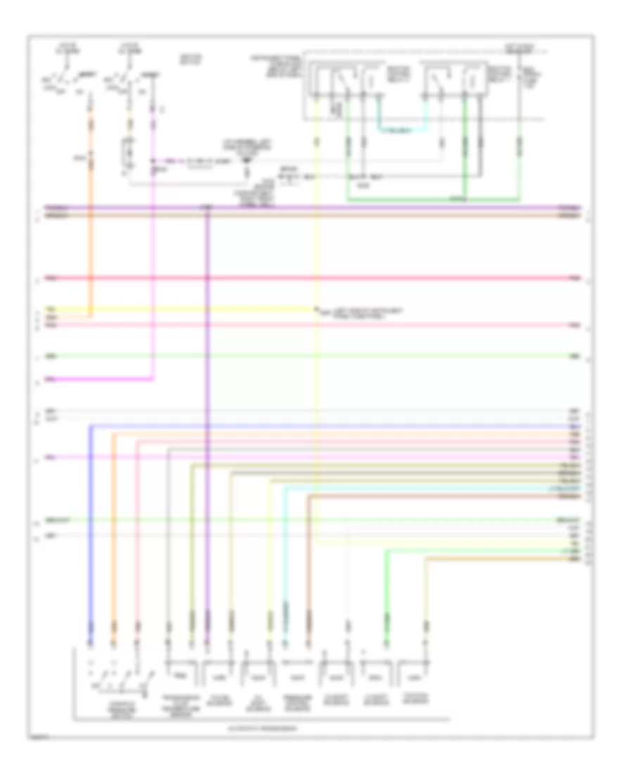
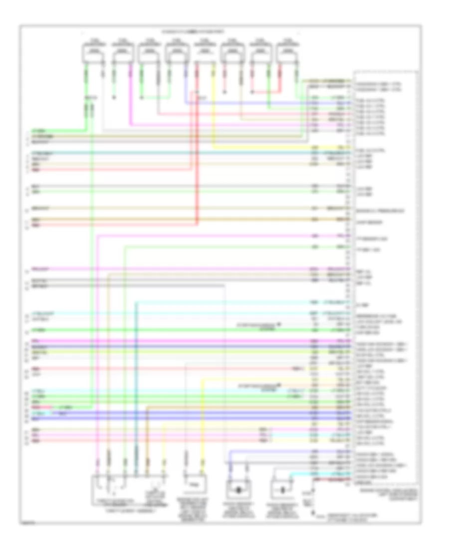
6.0L VIN U, Engine Performance Wiring Diagram (1 of 6) for Pontiac GTO 2005

List of elements for 6.0L VIN U, Engine Performance Wiring Diagram (1 of 6) for Pontiac GTO 2005:
- 5v ref a
- 5v ref b
- A/c refrig press sen sig
- A/c refrigerant pressure sensor (left front corner of engine compartment)
- A/t
- Accelerator pedal position (app) sensor
- Accessory voltage
- App sen 1 sig
- App sen 2 sig
- Auto trans fuse 15a
- Battery positive vol
- Bcm/engine control fuse 15a
- Bus +
- Bus -
- Computer data lines system
- Cooling fans system
- Cpp sw sig
- Crank vol
- Cruise control system
- Engine control module (ecm) (left side of engine compartment)
- Engine controls relay
- Engine ctrl rel coil ctrl
- Engine sensors fuse 15a
- Engine speed signal
- Exterior lights system
- Fan rel ctrl
- Fuel level sen
- Fuel pump relay ctrl
- Hot at all times
- Hot in run run or start
- Ign 1 vol
- Ign 3 vol
- Ign coil 1 ctrl
- Instrument panel cluster (ipc)
- Low ref
- M/t
- Mil
- Mil control
- Multi- function display
- Park neutral position sw
- Pnk
- Pnk s111
- Release sig
- Reverse lockout sol ctrl
- Reverse lockout solenoid (top left on transmission)
- S105
- S106
- S110
- Sensor signal
- Skip shift coil assembly
- Speedometer
- Starter rel coil ctrl
- Starting/ charging system
- Sw sig
- Tachometer
- Tan
- Underhood fuse block (on right side of engine compartment)
- Vss signal
6.0L VIN U, Engine Performance Wiring Diagram (2 of 6) for Pontiac GTO 2005
List of elements for 6.0L VIN U, Engine Performance Wiring Diagram (2 of 6) for Pontiac GTO 2005:
- (i/p harness, left side of steering column) s290
- (left side of instrument panel fuse panel)
- (not
- 1-2 shift solenoid
- 2-3 shift solenoid
- 3-2 shift solenoid
- Acc
- Automatic transmission
- Ecm signal fuse 7.5a
- Ecm/tcm control relay 1
- Ecm/tcm control relay 2
- G102 (engine compartment, right front wheel well)
- Hot at all times
- Hot in run or start
- Ignition switch
- Instrument panel fuse block (below left end of dash)
- Lock
- Manifold pressure switch
- Off
- Pnk
- Pressure control solenoid
- S109
- S238
- S289
- S291
- Sp100
- Start
- Tan
- Tcc en solenoid
- Tcc pwm solenoid
- Transmission fluid temperature sensor
- Used)
6.0L VIN U, Engine Performance Wiring Diagram (3 of 6) for Pontiac GTO 2005
List of elements for 6.0L VIN U, Engine Performance Wiring Diagram (3 of 6) for Pontiac GTO 2005:
- (in left exhaust pipe, after catalytic converter) heated oxygen sensor (ho2s) bank 1 sensor 2
- (in right exhaust pipe, after catalytic converter) heated oxygen sensor (ho2s) bank 2 sensor 2
- (in right exhaust pipe, forward of catalytic converter) heated oxygen sensor (ho2s) bank 2 sensor 1
- 1-2 shift sol
- 2-3 shift sol
- A/t
- Accessory vol
- Battery positive vol
- G104 (rear of engine, near left valve cover, attached to block)
- G105 (rear of engine, near left valve cover, attached to block)
- Ground
- Heated oxygen sensor (ho2s) bank 1 sensor 1 (in left exhaust pipe, forward of catalytic converter)
- Ign 1 vol
- Low ref
- M/t
- Nca
- Park/neutral position switch
- Pc sol valve
- Pnk
- Pressure sw sig a
- Pressure sw sig b
- Pressure sw sig c
- S129
- S246
- Shift sol valve 3
- Sw sig a
- Sw sig b
- Sw sig c
- Sw sig p
- Tcc pwm sol
- Tcc sol valve
- Tft sensor sig
- Transmission control module (tcm)
- Vehicle speed sensor (vss) (a/t) (in transmission)
- Vehicle speed sensor (vss) (m/t) (left rear of transmission)
- Vss
- Vss low sig
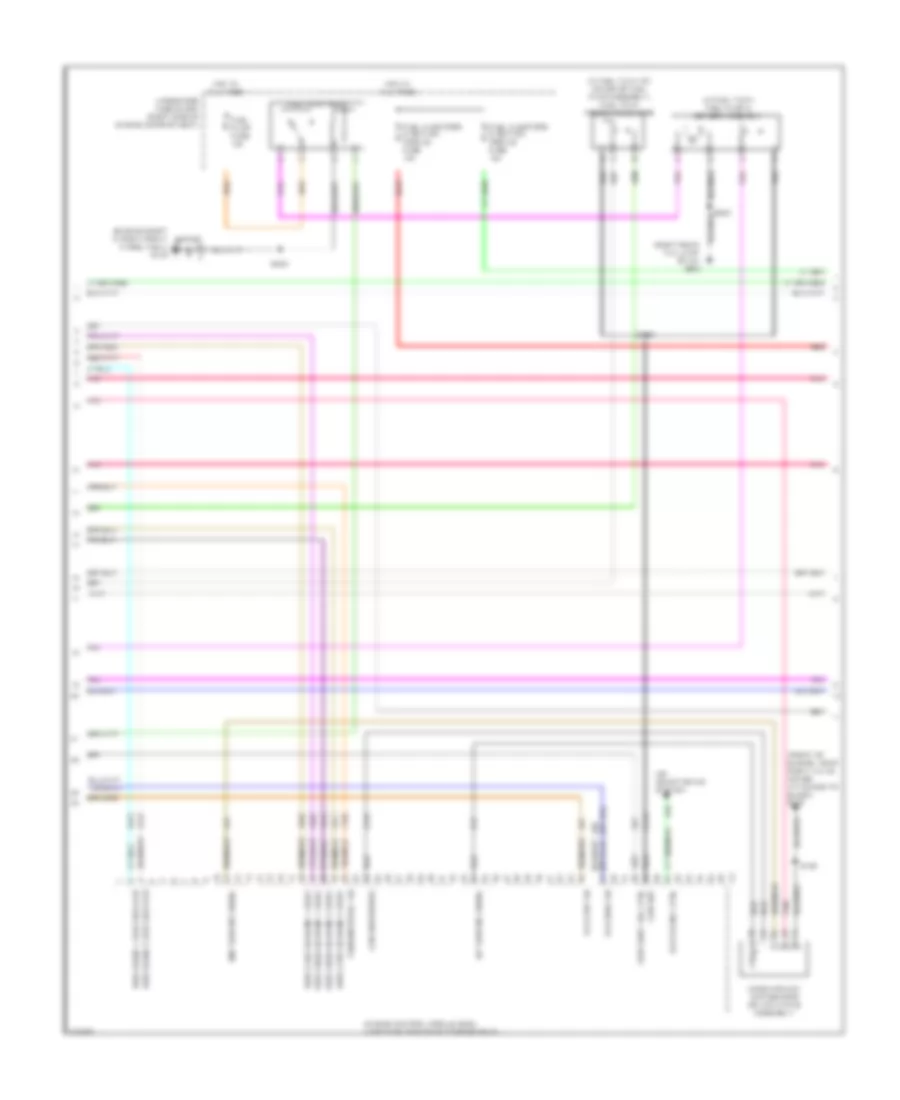
6.0L VIN U, Engine Performance Wiring Diagram (4 of 6) for Pontiac GTO 2005
List of elements for 6.0L VIN U, Engine Performance Wiring Diagram (4 of 6) for Pontiac GTO 2005:
- (engine compt in right front wheel well) g102
- (front of engine, near right valve cover, attached to block) g104
- (in fuel tank) fuel pump & sender assembly
- (in fuel tank, on cover of fuel pump assembly) fuel tank pressure sensor
- (or 381)
- (right rear tail lamp stud) g900
- Air conditioning system
- Clutch rel ctrl
- Engine control module (ecm) (left side of engine compartment)
- Fuel injectors & ignition module fuse 15a
- Fuel pump fuse 15a
- Fuel pump relay
- Ho2s bank 1 sen 2 heater
- Ho2s bank 2 sen 2 heater
- Ho2s high sig bank 1 sen 2
- Ho2s high sig bank 2 sen 2
- Ho2s low sig bank 1 sen 2
- Ho2s low sig bank 2 sen 2
- Hot at all times
- Iat sensor signal
- Low ref
- Low reference
- Maf sensor signal
- Mass airflow (maf) sensor (on air intake assembly)
- Park/neutral sig
- Pnk
- Red
- S129
- S158
- S232
- Skip shift sol ctrl
- Sp100
- Underhood fuse block (right side of engine compartment)
- Vss high sig
- Vss low sig
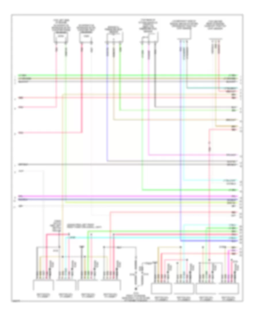
6.0L VIN U, Engine Performance Wiring Diagram (5 of 6) for Pontiac GTO 2005
List of elements for 6.0L VIN U, Engine Performance Wiring Diagram (5 of 6) for Pontiac GTO 2005:
- (2240mm from left front front park/turn signal light)
- (725mm (28.5 in) from left ignition module)
- (lower right side of engine, behind starter) crankshaft position (ckp) sensor
- (top center rear of engine) camshaft position (cmp) sensor
- (top left side of engine)
- (top rear of
- Engine oil pressure (eop) sensor
- Evaporative emissions (evap) canister purge solenoid
- Evaporative emissions (evap) canister vent solenoid
- G104 (front of engine, near right valve cover, attached to block)
- Ignition coil cylinder 1
- Ignition coil cylinder 2
- Ignition coil cylinder 3
- Ignition coil cylinder 4
- Ignition coil cylinder 5
- Ignition coil cylinder 6
- Ignition coil cylinder 7
- Ignition coil cylinder 8
- Intake manifold) manifold absolute pressure (map) sensor
- Nca
- Plug spark
- Pnk
- Red
- S128
- S130
- S132
- S133
- S154
- S155
- S159
- S160
- Spark plug
6.0L VIN U, Engine Performance Wiring Diagram (6 of 6) for Pontiac GTO 2005
List of elements for 6.0L VIN U, Engine Performance Wiring Diagram (6 of 6) for Pontiac GTO 2005:
- (in each cylinders intake port)
- (near right valve cover, attached to block)
- 5v ref
- Camp sensor
- Ckp sensor signal
- Duty cycle sig
- Ect sen sig
- Engine control module (ecm) (left side of engine compartment)
- Engine coolant temperature (ect) sensor (left side of engine, below generator)
- Engine oil pressure sig
- Evap sol ctrl
- Fuel inj 1 ctrl
- Fuel inj 2 ctrl
- Fuel inj 3 ctrl
- Fuel inj 4 ctrl
- Fuel inj 5 ctrl
- Fuel inj 6 ctrl
- Fuel inj 7 ctrl
- Fuel inj 8 ctrl
- Fuel injector 1
- Fuel injector 2
- Fuel injector 3
- Fuel injector 4
- Fuel injector 5
- Fuel injector 6
- Fuel injector 7
- Fuel injector 8
- G104
- Ground
- Ho2s bank 1 sen 1 ctrl
- Ho2s bank 2 sen 1 ctrl
- Ho2s high sig bank 1 sen 1
- Ho2s high sig bank 2 sen 1
- Ho2s low sig bank 1 sen 1
- Ho2s low sig bank 2 sen 1
- Ign coil 2 ctrl
- Ign coil 3 ctrl
- Ign coil 4 ctrl
- Ign coil 5 ctrl
- Ign coil 6 ctrl
- Ign coil 7 ctrl
- Ign coil 8 ctrl
- Knock sen 1 return
- Knock sen 1 signal
- Knock sen 2 return
- Knock sen 2 sig
- Knock sensor 1 (center of engine, below intake manifold)
- Knock sensor 2 (center of engine, below intake manifold)
- Low coolant level ind
- Low ref
- Map sen sig
- Red
- Ref vol
- Reference voltage
- S128
- S137
- S138
- Starting/charging system
- Tac motor ctrl-1
- Tac motor ctrl-2
- Throttle actuator control (tac) motor
- Throttle body assembly
- Throttle position (tp) sensor
- Tp sen 1 sig
- Tp sensor 2 sig
- Turn on sig
- Vent sol ctrl