ENGINE PERFORMANCE
2.7L
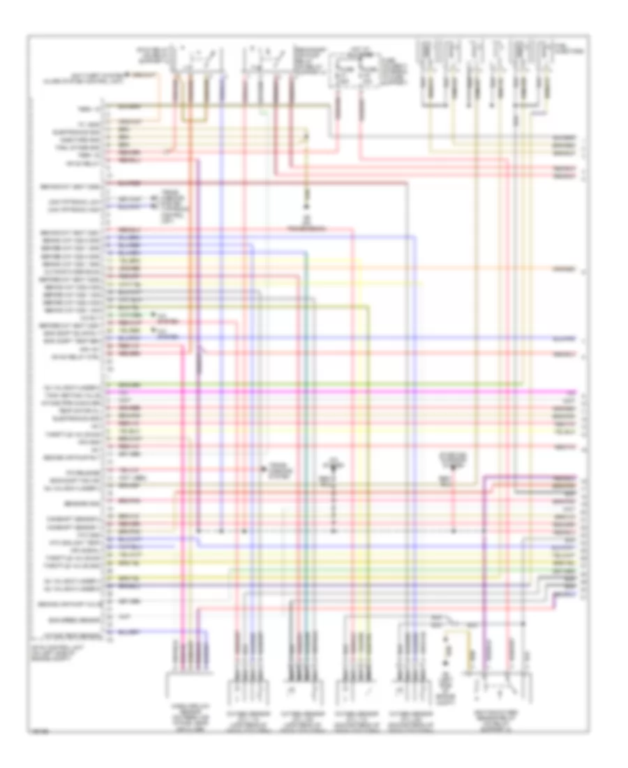
2.7L, Engine Performance Wiring Diagrams (1 of 3) for Porsche Boxster 2002

List of elements for 2.7L, Engine Performance Wiring Diagrams (1 of 3) for Porsche Boxster 2002:
- "w" lead
- (not used)
- +5v
- A/c rly
- A/c system
- Anti-theft system (alarm system control unit)
- Automatic egr exam
- Before cat heat o2s1
- Before cat heat o2s2
- Before cat o2s 1 gnd
- Before cat o2s 1 sig
- Before cat o2s 2 gnd
- Before cat o2s 2 sig
- Behind cat heat o2s1
- Behind cat heat o2s2
- Behind cat o2s 1 gnd
- Behind cat o2s 1 sig
- Behind cat o2s 2 gnd
- Behind cat o2s 2 sig
- Camshaft sensor 1
- Camshaft sensor 2
- Can tiptronic high
- Can tiptronic low
- Electronics gnd
- Eng compt blwr rly
- Eng compt fan ind
- Eng compt temp sen
- Eng speed sensor
- Final stage gnd
- Fuel injectors
- Fuse c1 25a
- Fuse c2 30a
- Fuse holder c (integral to fuse support)
- G8 (left side of engine compt)
- G9 (on transmission)
- Hfm +5v
- Hfm gnd
- Hfm signal
- Hot at all times
- Ignition/oxygen sensor relay (on relay support 2)
- Inj valve/cylinder 3
- Inj valve/cylinder 4
- Inj valve/cylinder 5
- Inj valve/cylinder 6
- Injectors gnd
- Intake pipe chg-over
- Intake temp sensor
- Mass airflow sensor (on fresh air intake, near air filter)
- Mfi+di relay
- Mfi+di relay ctrl
- Mfi-di control unit (on left side of engine compt)
- Mfi-di relay (on relay support 2)
- Nca
- Ntc coolant temp
- Ntc gnd
- Oxygen sensor (cyl 1-3) (downstream of catalytic conv)
- Oxygen sensor (cyl 1-3) (upstream of catalytic conv)
- Oxygen sensor (cyl 4-6) (downstream of catalytic conv)
- Oxygen sensor (cyl 4-6) (upstream of catalytic conv)
- P/n release
- Second air pump rly
- Second air pump valve
- Secondary air pump relay (on relay support 2)
- Sensors gnd
- Starting/ charging system
- Tank venting valve
- Temp motor oil
- Term. 15
- Term. 30
- Throttle valve gnd
- Throttle valve sig
- Trans- missions system
- Trans- missions system (tiptronic control unit)
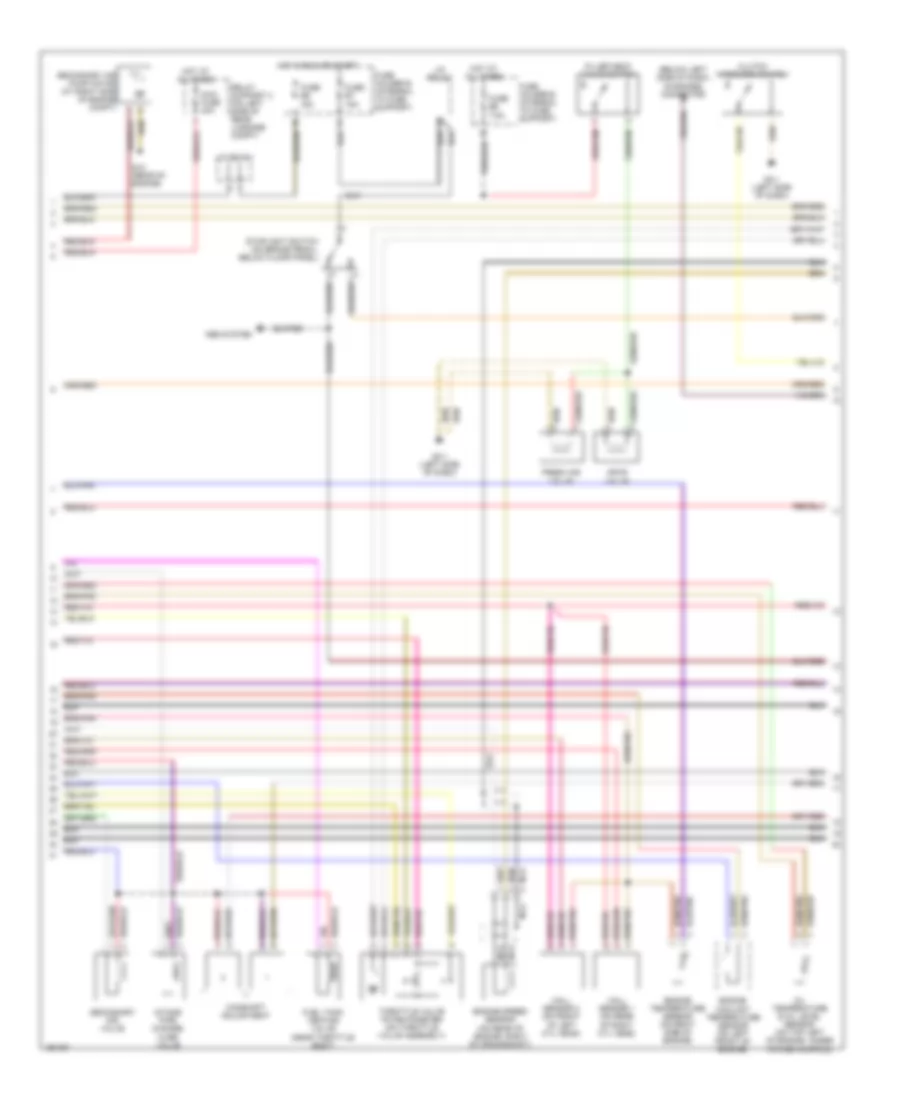
2.7L, Engine Performance Wiring Diagrams (2 of 3) for Porsche Boxster 2002
List of elements for 2.7L, Engine Performance Wiring Diagrams (2 of 3) for Porsche Boxster 2002:
- (below left side of dash) diagnosis connector
- Abs system
- Camshaft adjustment
- Clutch interlock switch
- Engine coolant temperature sensor (on left front of engine)
- Engine speed sensor (on rear of engine, right of crankshaft)
- Engine temperature sensor (on right side of engine)
- Filler neck valve switch
- Fresh air valve
- Fuel tank venting valve (near throttle body)
- Fuse b7 15a
- Fuse b8 15a
- Fuse e6 7.5a
- Fuse holder b (integral to fuse support)
- Fuse holder e (integral to fuse support)
- G12 (rear of engine)
- G3-1 (left side of dash)
- Hall sensor 1 (on rear of right cyl head)
- Hall sensor 2 (on front of left cyl head)
- Hot at all times
- Hot in run or start
- Intake pipe change- over valve
- J/c bs14/2
- J/c bs16/1
- Maxi fuse 40a
- Nca
- Oil temperature & oil level sensor (on top left of engine, under intake manifold)
- Orvr valve
- Relay support 2 (on left side of rear luggage compt)
- Secondary air pump motor (at right side of engine compt)
- Secondary air valve
- Stoplight switch (on brake pedal, below floor panel)
- Throttle valve potentiometer (on throttle valve assembly)
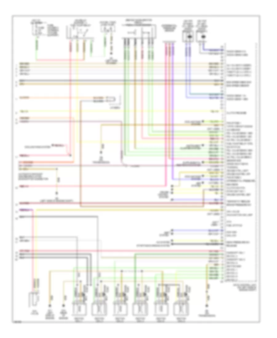
2.7L, Engine Performance Wiring Diagrams (3 of 3) for Porsche Boxster 2002
List of elements for 2.7L, Engine Performance Wiring Diagrams (3 of 3) for Porsche Boxster 2002:
- (behind accelerator pedal) pedal value sensor
- (in fuel tank) fuel pump
- (not used)
- (on relay support 1) fuel pump relay
- (on top of left cyl head) knock sensor 2
- (on top of right cyl head) knock sensor 1
- +5v pdl value sens 1
- +5v pdl value sens 2
- A/c demand
- A/c system
- Aav valve
- Abs system
- Automatic exhaust gas recirculation examination connector
- Brake pressure sw
- Camshaft adj 1
- Camshaft adj 2
- Can high
- Can low
- Clutch release
- Clutch switch
- Cooling fans system
- Crash shut-down
- Cruise control off
- Cruise control set
- Cruise control system
- Cruise ctrl light
- Differential pressure
- Differential pressure sensor
- Dim status
- Eng speed sens shd
- Eng speed sensor
- Eso rear
- Fan stage 1
- Fan stage 2
- Fuel pump relay ctrl
- Fuel status
- Fuse c4 30a
- Fuse holder c (integral to fuse support)
- G11 (left side of engine)
- G12 (rear of engine)
- G3 (left side of dash)
- G8 (left side of engine compt)
- G9 (on transmission)
- Hot at all times
- Ign coil 1
- Ign coil 2
- Ign coil 3
- Ign coil 4
- Ign coil 5
- Ign coil 6
- Ignition coil 1
- Ignition coil 2
- Ignition coil 3
- Ignition coil 4
- Ignition coil 5
- Ignition coil 6
- Ignition gnd
- Inj valve/cylinder 1
- Inj valve/cylinder 2
- Instrument cluster system
- J/c bs6/2
- Knock sens 1 gnd
- Knock sens 1 in
- Knock sens 2 gnd
- Knock sens 2 in
- Kva
- Malfunction ind lamp
- Mean pressure sw
- Mfi-di control unit (on left side of engine compt)
- Nca
- Pdl value sens 1 gnd
- Pdl value sens 1 sig
- Pdl value sens 2 gnd
- Pdl value sens 2 sig
- Plug spark
- Release
- Sensor gnd
- Spark plug
- Starting/charging system
- Stoplight sw 1
- Tempostat resume
- Throttle vlv mtr (+)
- Throttle vlv mtr (-)
- Tiptr variant coding
- Tn-signal
3.2L
3.2L, Engine Performance Wiring Diagrams (1 of 3) for Porsche Boxster 2002
List of elements for 3.2L, Engine Performance Wiring Diagrams (1 of 3) for Porsche Boxster 2002:
- "w" lead
- (not used)
- +5v
- A/c rly
- A/c system
- Anti-theft system (alarm system control unit)
- Automatic egr exam
- Before cat heat o2s1
- Before cat heat o2s2
- Before cat o2s 1 gnd
- Before cat o2s 1 sig
- Before cat o2s 2 gnd
- Before cat o2s 2 sig
- Behind cat heat o2s1
- Behind cat heat o2s2
- Behind cat o2s 1 gnd
- Behind cat o2s 1 sig
- Behind cat o2s 2 gnd
- Behind cat o2s 2 sig
- Camshaft sensor 1
- Camshaft sensor 2
- Can tiptronic high
- Can tiptronic low
- Electronics gnd
- Eng compt blwr rly
- Eng compt fan ind
- Eng compt temp sen
- Eng speed sensor
- Final stage gnd
- Fuel injectors
- Fuse c1 25a
- Fuse c2 30a
- Fuse holder c (integral to fuse support)
- G8 (left side of engine compt)
- G9 (on transmission)
- Hfm +5v
- Hfm gnd
- Hfm signal
- Hot at all times
- Ignition/oxygen sensor relay (on relay support 2)
- Inj valve/cylinder 3
- Inj valve/cylinder 4
- Inj valve/cylinder 5
- Inj valve/cylinder 6
- Injectors gnd
- Intake pipe chg-over
- Intake temp sensor
- Mass airflow sensor (on fresh air intake, near air filter)
- Mfi+di relay
- Mfi+di relay ctrl
- Mfi-di control unit (on left side of engine compt)
- Mfi-di relay (on relay support 2)
- Nca
- Ntc coolant temp
- Ntc gnd
- Oxygen sensor (cyl 1-3) (downstream of catalytic conv)
- Oxygen sensor (cyl 1-3) (upstream of catalytic conv)
- Oxygen sensor (cyl 4-6) (downstream of catalytic conv)
- Oxygen sensor (cyl 4-6) (upstream of catalytic conv)
- P/n release
- Second air pump rly
- Second air pump valve
- Secondary air pump relay (on relay support 2)
- Sensors gnd
- Starting/ charging system
- Tank venting valve
- Temp motor oil
- Term. 15
- Term. 30
- Throttle valve gnd
- Throttle valve sig
- Trans- missions system
- Trans- missions system (tiptronic control unit)
3.2L, Engine Performance Wiring Diagrams (2 of 3) for Porsche Boxster 2002
List of elements for 3.2L, Engine Performance Wiring Diagrams (2 of 3) for Porsche Boxster 2002:
- (below left side of dash) diagnosis connector
- Abs system
- Camshaft adjustment
- Clutch interlock switch
- Engine coolant temperature sensor (on left front of engine)
- Engine speed sensor (on rear of engine, right of crankshaft)
- Engine temperature sensor (on right side of engine)
- Filler neck valve switch
- Fresh air valve
- Fuel tank venting valve (near throttle body)
- Fuse b7 15a
- Fuse b8 15a
- Fuse e6 7.5a
- Fuse holder b (integral to fuse support)
- Fuse holder e (integral to fuse support)
- G12 (rear of engine)
- G3-1 (left side of dash)
- Hall sensor 1 (on rear of right cyl head)
- Hall sensor 2 (on front of left cyl head)
- Hot at all times
- Hot in run or start
- Intake pipe change- over valve
- J/c bs14/2
- J/c bs16/1
- Maxi fuse 40a
- Nca
- Oil temperature & oil level sensor (on top left of engine, under intake manifold)
- Orvr valve
- Relay support 2 (on left side of rear luggage compt)
- Secondary air pump motor (at right side of engine compt)
- Secondary air valve
- Stoplight switch (on brake pedal, below floor panel)
- Throttle valve potentiometer (on throttle valve assembly)
3.2L, Engine Performance Wiring Diagrams (3 of 3) for Porsche Boxster 2002
List of elements for 3.2L, Engine Performance Wiring Diagrams (3 of 3) for Porsche Boxster 2002:
- (behind accelerator pedal) pedal value sensor
- (in fuel tank) fuel pump
- (not used)
- (on relay support 1) fuel pump relay
- (on top of left cyl head) knock sensor 2
- (on top of right cyl head) knock sensor 1
- +5v pdl value sens 1
- +5v pdl value sens 2
- A/c demand
- A/c system
- Aav valve
- Abs system
- Automatic exhaust gas recirculation examination connector
- Brake pressure sw
- Camshaft adj 1
- Camshaft adj 2
- Can high
- Can low
- Clutch release
- Clutch switch
- Cooling fans system
- Crash shut-down
- Cruise control off
- Cruise control set
- Cruise control system
- Cruise ctrl light
- Differential pressure
- Differential pressure sensor
- Dim status
- Eng speed sens shd
- Eng speed sensor
- Eso rear
- Fan stage 1
- Fan stage 2
- Fuel pump relay ctrl
- Fuel status
- Fuse c4 30a
- Fuse holder c (integral to fuse support)
- G11 (left side of engine)
- G12 (rear of engine)
- G3 (left side of dash)
- G8 (left side of engine compt)
- G9 (on transmission)
- Hot at all times
- Ign coil 1
- Ign coil 2
- Ign coil 3
- Ign coil 4
- Ign coil 5
- Ign coil 6
- Ignition coil 1
- Ignition coil 2
- Ignition coil 3
- Ignition coil 4
- Ignition coil 5
- Ignition coil 6
- Ignition gnd
- Inj valve/cylinder 1
- Inj valve/cylinder 2
- Instrument cluster system
- J/c bs6/2
- Knock sens 1 gnd
- Knock sens 1 in
- Knock sens 2 gnd
- Knock sens 2 in
- Kva
- Malfunction ind lamp
- Mean pressure sw
- Mfi-di control unit (on left side of engine compt)
- Nca
- Pdl value sens 1 gnd
- Pdl value sens 1 sig
- Pdl value sens 2 gnd
- Pdl value sens 2 sig
- Plug spark
- Release
- Sensor gnd
- Spark plug
- Starting/charging system
- Stoplight sw 1
- Tempostat resume
- Throttle vlv mtr (+)
- Throttle vlv mtr (-)
- Tiptr variant coding
- Tn-signal