ENGINE PERFORMANCE
2.0L TURBO
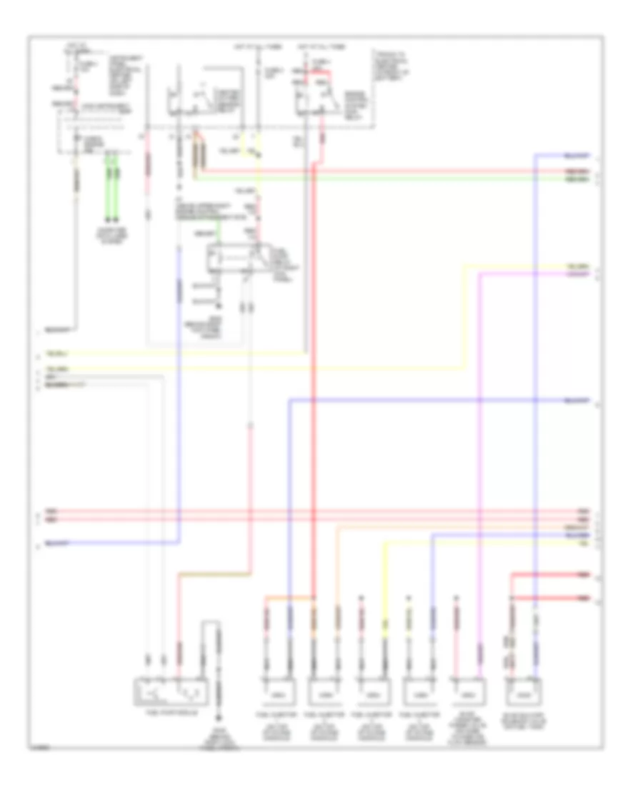
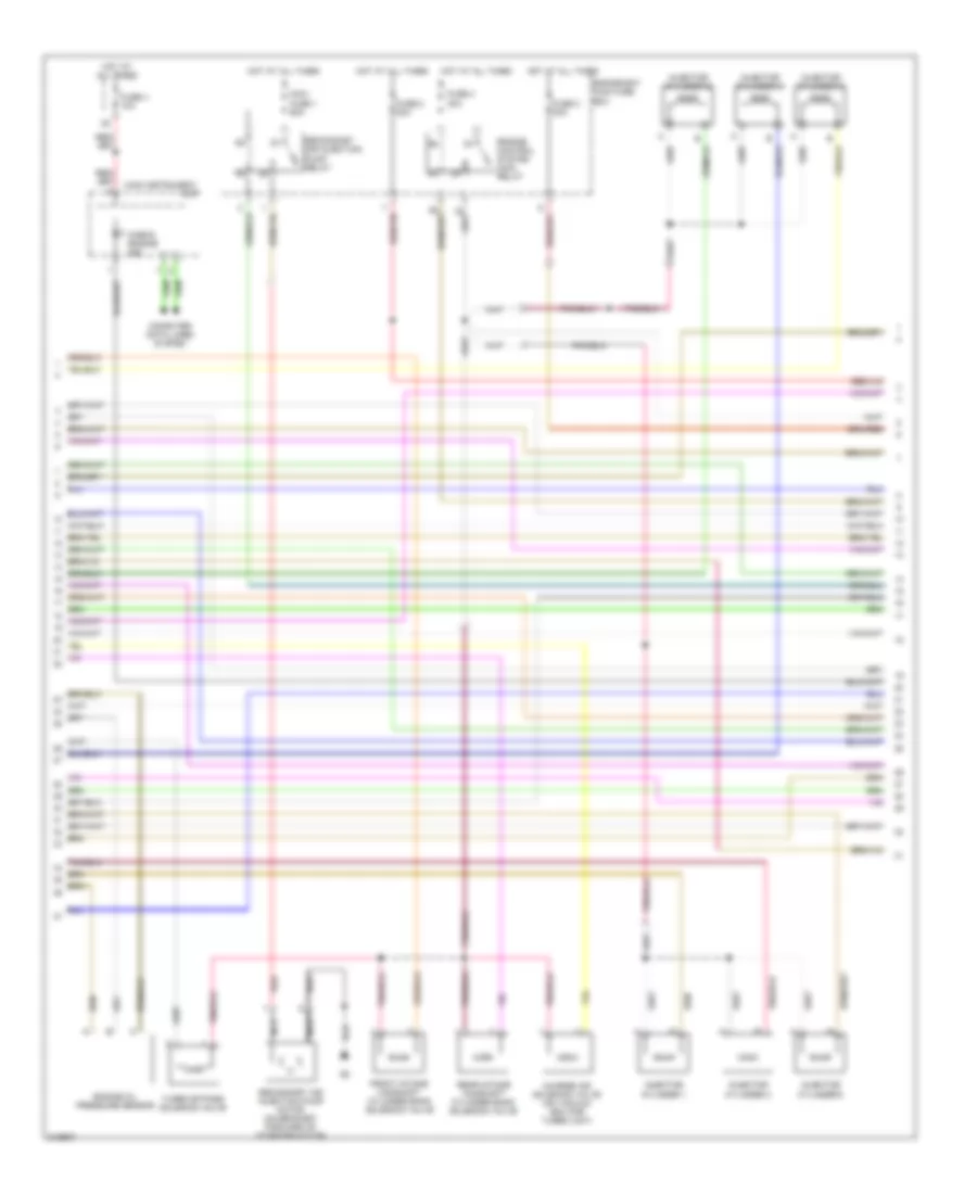
2.0L Turbo, Engine Performance Wiring Diagram (1 of 4) for Saab 9-3 Aero 2006

List of elements for 2.0L Turbo, Engine Performance Wiring Diagram (1 of 4) for Saab 9-3 Aero 2006:
- A/c pressure sensor (near left front corner of air filter)
- A10-1
- Accelerator pedal position sensor (on pedal bracket)
- Air conditioning system
- Brake light switch (above brake pedal, on bracket)
- C10
- C31-20
- Computer data lines system
- Cruise control brake switch (on brake pedal bracket)
- Cruise control clutch switch (near top of clutch
- E11
- E15-29
- E15-5
- E201-1
- E30-17
- E30-18
- E30-19
- E30-35
- E31-11
- E31-12
- E31-13
- E31-21
- E31-30
- E31-7
- E64
- E65
- E66
- E67
- E68
- E69
- E70
- E71
- E71-6
- E72
- E73-1
- E74-1
- E75
- E77
- E84
- Engine oil level switch (left side of oil pan)
- Evap pressure sensor (on fuel tank by fuel pump)
- Fuse 2 10a
- Fuse 2 5a
- Fuse 21 7.5a
- Fuse 4 10a
- Fuse 6 7.5a
- G7 (above upper right engine control module attachment eye)
- Hot at all times
- Hot in on or start
- Hs1
- Hs2
- Ignition switch module
- Instrument panel electrical center (on left side of dash)
- M24
- Pedal)
- Power distribution system
- Power steering fluid pressure sensor (on top of servo pump)
- Red
- Starting/ charging system
- Starting/charging system
- Trionic control module (front of engine)
- Underhood electrical center (left side of engine bay)
- X+ off & on output
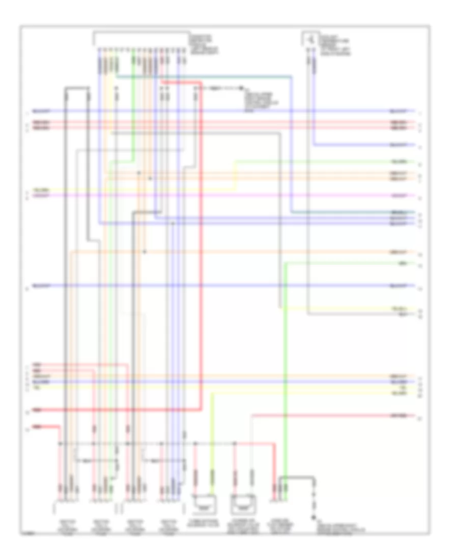
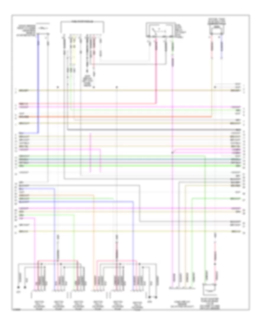
2.0L Turbo, Engine Performance Wiring Diagram (2 of 4) for Saab 9-3 Aero 2006
List of elements for 2.0L Turbo, Engine Performance Wiring Diagram (2 of 4) for Saab 9-3 Aero 2006:
- Check engine ind
- Computer data lines system
- Engine control system main relay
- Evap canister purge valve (on hose to mass air flow sensor)
- Evap shut-off solenoid valve (on fuel tank)
- Fuel injector (on top of intake manifold)
- Fuel pump module
- Fuel pump relay (at right kick panel)
- Fuse 2 20a
- Fuse 4 10a
- Fuse 4 30a
- G34s (behind right kick panel (front))
- G7 (above upper right engine control module attachment eye)
- Heated oxygen sensor relay
- Hot at all times
- Instrument panel electrical center (on left side of dash)
- Main instrument
- Nca
- Red
- Trionic t8 electrical center (in front of battery)
- Unit
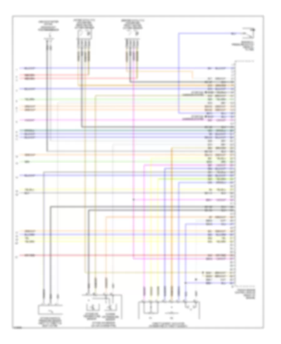
2.0L Turbo, Engine Performance Wiring Diagram (3 of 4) for Saab 9-3 Aero 2006
List of elements for 2.0L Turbo, Engine Performance Wiring Diagram (3 of 4) for Saab 9-3 Aero 2006:
- Charge air solenoid valve (on vacuum box for turbo unit)
- Coolant temperature sensor (at front left side of engine)
- G7 (above upper right engine control module attachment eye)
- Ignition coil 1 (on spark plug)
- Ignition coil 2 (on spark plug)
- Ignition coil 3 (on spark plug)
- Ignition coil 4 (on spark plug)
- Ionization detection module (left rear of engine compt)
- Mass air- flow sensor (on intake air duct)
- Red
- Turbo bypass solenoid valve
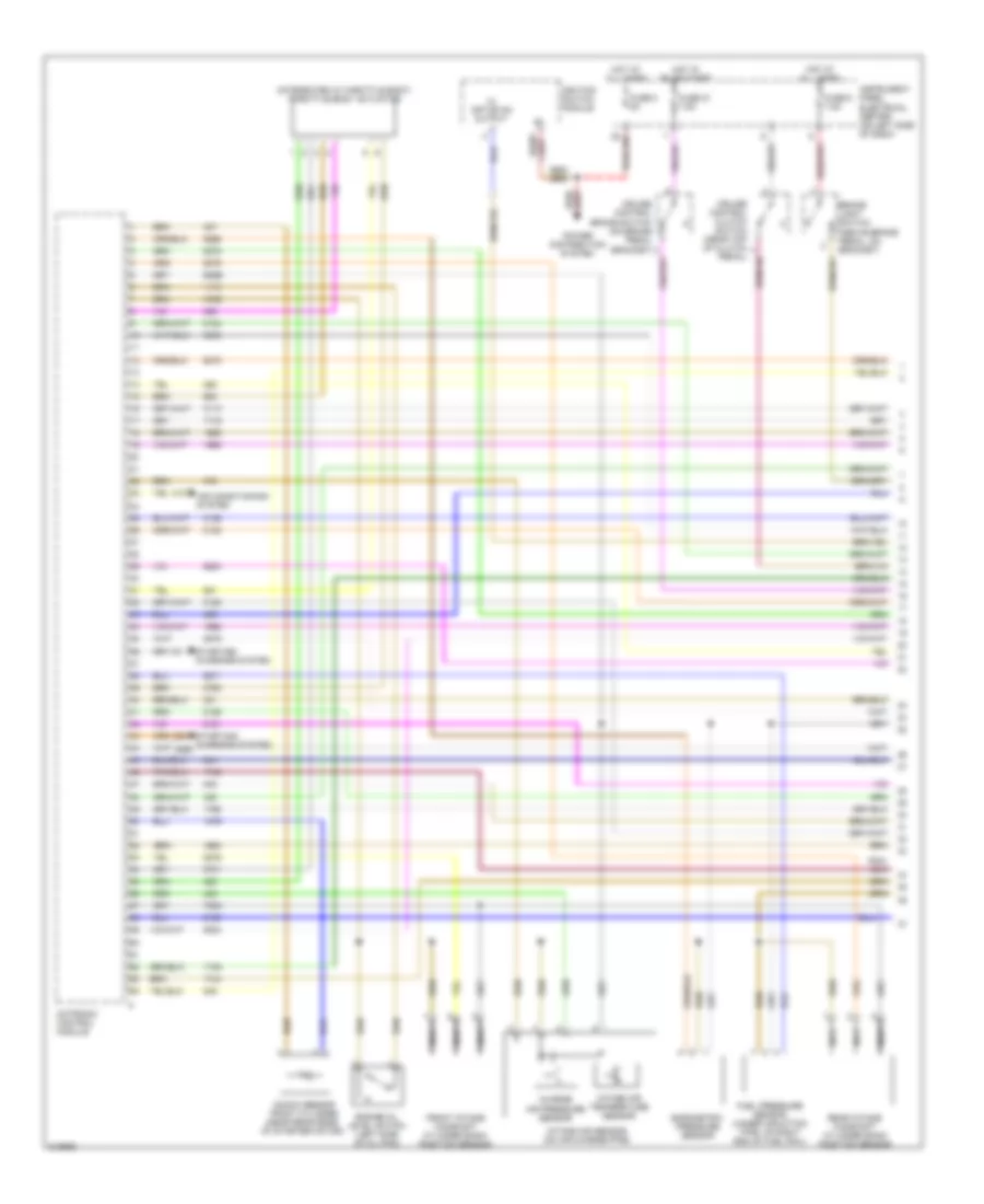
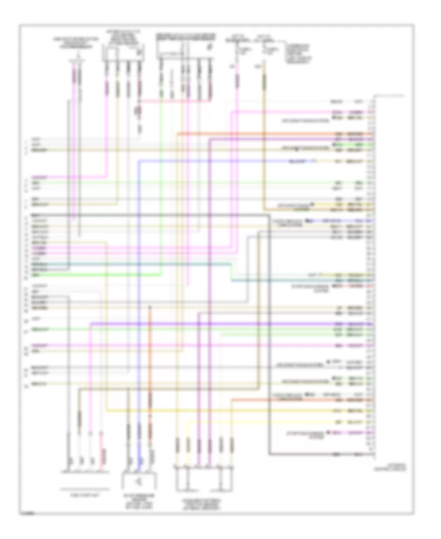
2.0L Turbo, Engine Performance Wiring Diagram (4 of 4) for Saab 9-3 Aero 2006
List of elements for 2.0L Turbo, Engine Performance Wiring Diagram (4 of 4) for Saab 9-3 Aero 2006:
- (above starter motor)
- (after catalytic converter) rear heated oxygen sensor
- (before catalytic converter) front heated oxygen sensor
- Charge air pressure sensor
- Crankshaft position sensor
- E12
- E126
- E127
- E13
- E15
- E16
- E17
- E18
- E20
- E200
- E21
- E210
- E22
- E23
- E31-10
- E31-22
- E31-23
- E31-24
- E31-26
- E31-27
- E34-12
- E34-22
- E34-32
- E34-42
- E38
- E40
- E41
- E42
- E43
- E49-1
- E49-2
- E51
- E52
- E53
- E54
- E55-1
- E55-2
- E56-1
- E56-2
- E57
- E58
- E63
- E80-1
- E80-2
- E81
- E83
- Engine oil pressure switch (near oil filter)
- Intake air sensor (on air charge pipe)
- Intake air temperature sensor
- Intake manifold pressure sensor (next to throttle body motor)
- Starting/ charging system
- Throttle body actuator (integrated in throttle body)
- Trionic engine control module (front of engine)
2.8L TURBO
2.8L Turbo, Engine Performance Wiring Diagram (1 of 4) for Saab 9-3 Aero 2006
List of elements for 2.8L Turbo, Engine Performance Wiring Diagram (1 of 4) for Saab 9-3 Aero 2006:
- (integrated in throttle body) throttle body actuator
- 470d
- 605e
- 705c
- Air conditioning system
- Barometric pressure sensor
- Brake light switch (above brake pedal, on bracket)
- Charge air pressure sensor
- Cruise control brake switch (on brake pedal bracket)
- Cruise control clutch switch (near top of clutch
- Engine oil level switch (left side of oil pan)
- Front intake camshaft cylinder bank position sensor
- Fuel pressure sensor (under induction pipe, on right end of fuel rail)
- Fuse 2 5a
- Fuse 21 7.5a
- Fuse 6 7.5a
- Hot at all times
- Hot in on or start
- Ignition switch module
- Instrument panel electrical center (on left side of dash)
- Intake air sensor (on air charge pipe)
- Intake air temperature sensor
- Knock sensor front cylinder (near rear edge of starter motor)
- Motronic control module
- Nca
- Pedal)
- Power distribution system
- Rear intake camshaft cylinder bank position sensor
- Starting/ charging system
- X+ off or on output
2.8L Turbo, Engine Performance Wiring Diagram (2 of 4) for Saab 9-3 Aero 2006
List of elements for 2.8L Turbo, Engine Performance Wiring Diagram (2 of 4) for Saab 9-3 Aero 2006:
- Charge air solenoid valve (on vacuum box for turbo unit)
- Check engine ind
- Computer data lines system
- Engine bay main fuse box
- Engine control system main relay
- Engine oil pressure sensor
- Front intake camshaft cylinder bank solenoid valve
- Fuse 2 20a
- Fuse 3 20a
- Fuse 4 10a
- Fuse 4 30a
- Hot at all times
- Injector cylinder 1
- Injector cylinder 2
- Injector cylinder 3
- Injector cylinder 4
- Injector cylinder 5
- Injector cylinder 6
- Main instrument
- Maxi fuse 1 60a
- Nca
- Rear intake camshaft cylinder bank solenoid valve
- Red
- Secondary air injection pump motor (on bracket forward of starter motor)
- Secondary air injection pump relay
- Turbo bypass solenoid valve
- Unit
2.8L Turbo, Engine Performance Wiring Diagram (3 of 4) for Saab 9-3 Aero 2006
List of elements for 2.8L Turbo, Engine Performance Wiring Diagram (3 of 4) for Saab 9-3 Aero 2006:
- (on fuel tank) evap shut-off solenoid valve
- E10
- E2-33
- E30
- E31-11
- E31-74
- Evap canister purg solenoid valve (on hose to mass air flow sensor)
- Fuel pump module
- Fuel pump relay (at right kick panel)
- G33p (behind left kick panel (rear))
- G7f
- G7r
- Ignition coil 1 (on spark plug)
- Ignition coil 2 (on spark plug)
- Ignition coil 3 (on spark plug)
- Ignition coil 4 (on spark plug)
- Ignition coil 5 (on spark plug)
- Ignition coil 6 (on spark plug)
- Knock sensor front cylinder (near rear edge of starter motor)
- Mass airflow sensor (on intake air duct)
2.8L Turbo, Engine Performance Wiring Diagram (4 of 4) for Saab 9-3 Aero 2006
List of elements for 2.8L Turbo, Engine Performance Wiring Diagram (4 of 4) for Saab 9-3 Aero 2006:
- (above starter motor) crankshaft position sensor
- (after catalytic converter) rear heated oxygen sensor
- (before catalytic converter) front heated oxygen sensor
- (or hs1-2)
- (or hs2-2)
- A10-1
- Accelerator pedal position sensor (on pedal bracket)
- Air conditioning system
- C10
- C25
- C26
- C27
- C31-20
- Computer data lines system
- E11
- E15-4
- E150
- E201-1
- E30-15
- E30-35
- E30-7
- E31-1
- E41
- E48
- E63
- E64
- E65
- E66
- E67
- E68
- E69
- E70
- E71
- E72
- E74-1
- E75
- E76-1
- E89
- E90
- E91
- Evap pressure sensor (on fuel tank by fuel pump)
- Fuel pump unit
- Fuse 2 10a
- Fuse 4 10a
- Hot at all times
- Hot in on or start
- Hs1
- Hs2
- M24
- Motronic control module
- Nca
- Starting/charging system
- Underhood electrical center (left side of engine bay)