ENGINE PERFORMANCE
2.4L VIN 5
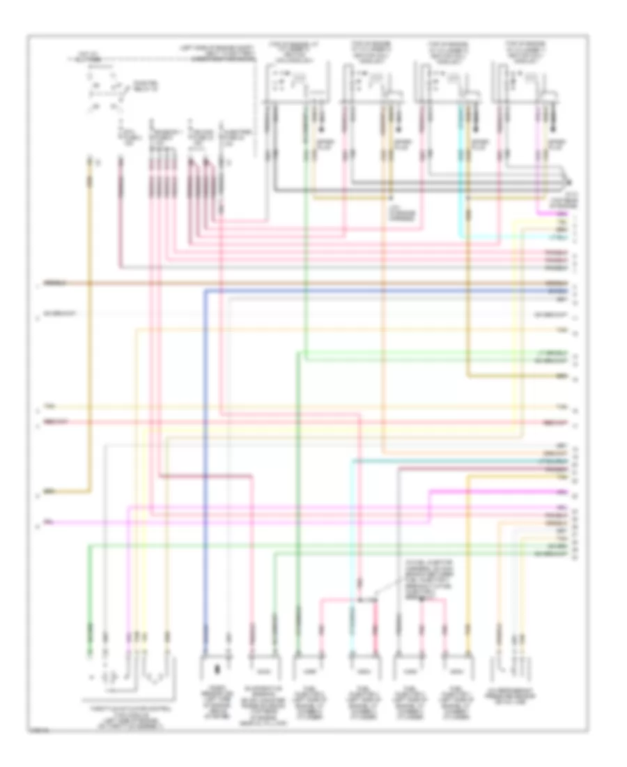
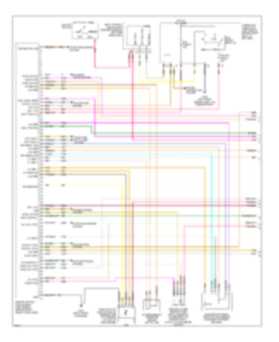
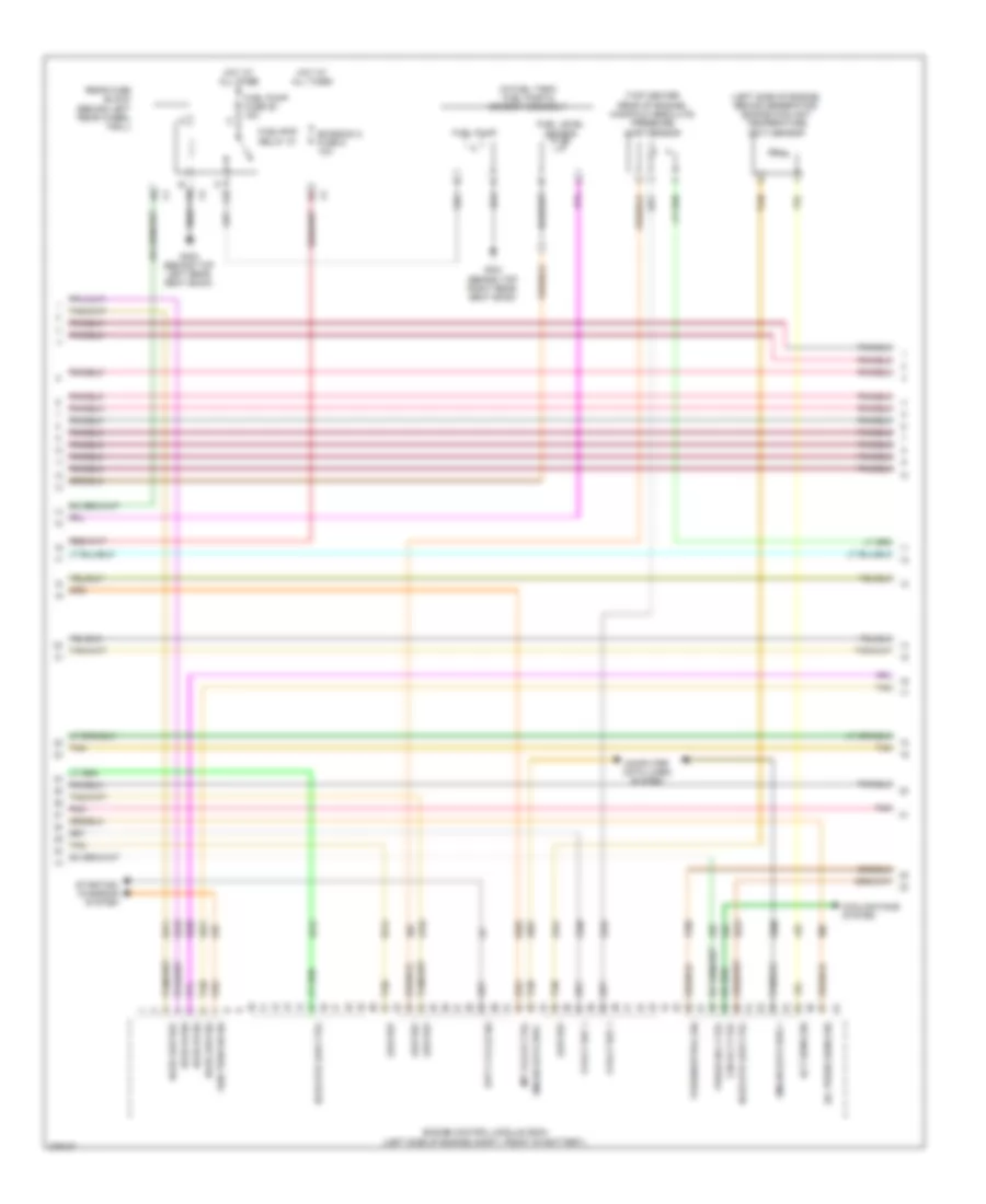
2.4L VIN 5, Engine Controls Wiring Diagram (1 of 4) for Saturn Aura XE 2008

List of elements for 2.4L VIN 5, Engine Controls Wiring Diagram (1 of 4) for Saturn Aura XE 2008:
- (center console, left side near dash) body control module (bcm)
- 5v ref
- 5v ref 1
- 5v ref 2
- Acc
- Acc volt
- Acc voltage
- Accelerator pedal position (app) sensor (accelerator pedal bracket)
- Air conditioning system
- Anti-lock brakes system
- App sensor 1
- App sensor 2
- Bat
- C10
- Clutch rly ctrl
- Computer data lines system
- Cooling fans system
- Driver information center (dic)
- Ecm fuse 13 10a
- Ecm ign fuse 16 10a
- Engine control module (ecm) (left side of engine compt, behind battery)
- Evap sol ctrl
- Evaporative emission (evap) canister vent solenoid valve (right side of fuel tank)
- Exterior lights system
- F pmp rly ctrl
- Fan rly ctrl
- Fuel level sens
- Fuel tank pressure (ftp) sensor (top of fuel pump & sender assembly)
- G109 (left front engine compt, on core support)
- Gmlan data
- Hot at all times
- Ign
- Ign 1
- Ign 1 volt
- Ign 1 voltage
- Ignition switch
- Instrument panel cluster (ipc)
- Logic
- Low ref
- Malfunc- tion indicator lamp
- Mil ctrl
- Off
- Pnk
- Press sens sig
- Rly coil ctrl
- Rly ctrl
- Run
- Run/ crank relay 32
- Start
- Starting/charging system
- Stp lmp sw sig
- Tan
- Underhood fuse block (left side of engine compt, next to battery)
- Vacuum sens sig
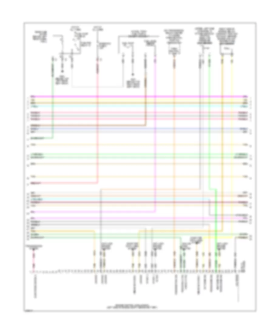
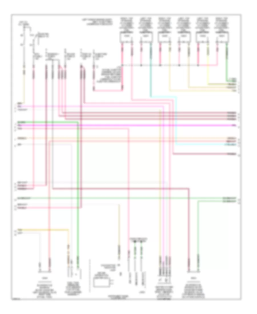
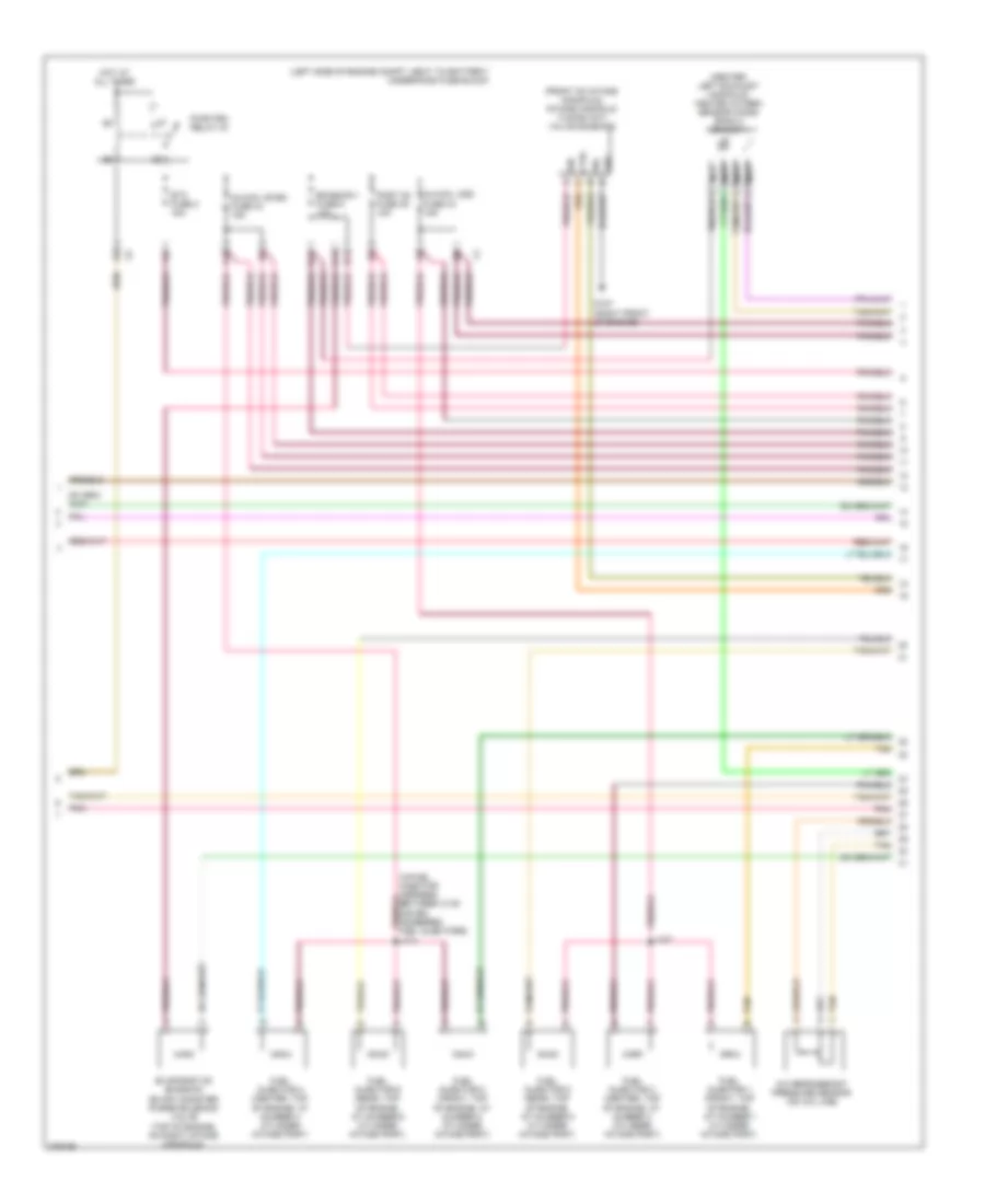
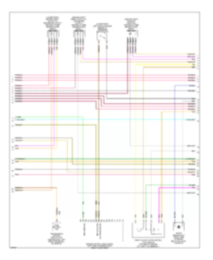
2.4L VIN 5, Engine Controls Wiring Diagram (2 of 4) for Saturn Aura XE 2008
List of elements for 2.4L VIN 5, Engine Controls Wiring Diagram (2 of 4) for Saturn Aura XE 2008:
- (in fuel injector harness, on main branch between fuel injector 3 breakout & fuel injector 2 breakout)
- (left side of engine compt, next to battery) underhood fuse block
- (top of engine, at cylinder 1) ignition coil/ module 1
- (top of engine, at cylinder 2) ignition coil/ module 2
- (top of engine, at cylinder 3) ignition coil/ module 3
- (top of engine, at cylinder 4) ignition coil/module 4
- A/c refrigerant pressure sensor (on a/c line)
- A10
- B11
- C11
- D11
- E11
- Emission 1 fuse 6 10a
- Etc fuse 2 15a
- Evaporative emission (evap) canister purge solenoid (top rear of engine, near oil fill cap)
- Fuel injector 1 (left side of engine, at number 1 cylinder)
- Fuel injector 2 (left side of engine, at number 2 cylinder)
- Fuel injector 3 (left side of engine, at number 3 cylinder)
- Fuel injector 4 (left side of engine, at number 4 cylinder)
- G110 (top rear of engine)
- Hot at all times
- Ign mod fuse 43 15a
- Injectors fuse 44 10a
- J121 (in engine harness)
- J130
- Knock sensor (ks) (left side of engine, above starter)
- Nca
- Pnk
- Pwr/trn relay 33
- Spark plug
- Tan
- Throttle actuator control (tac) module (left side of engine, on throttle assembly)
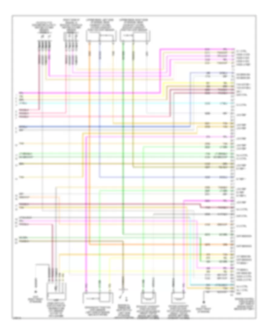
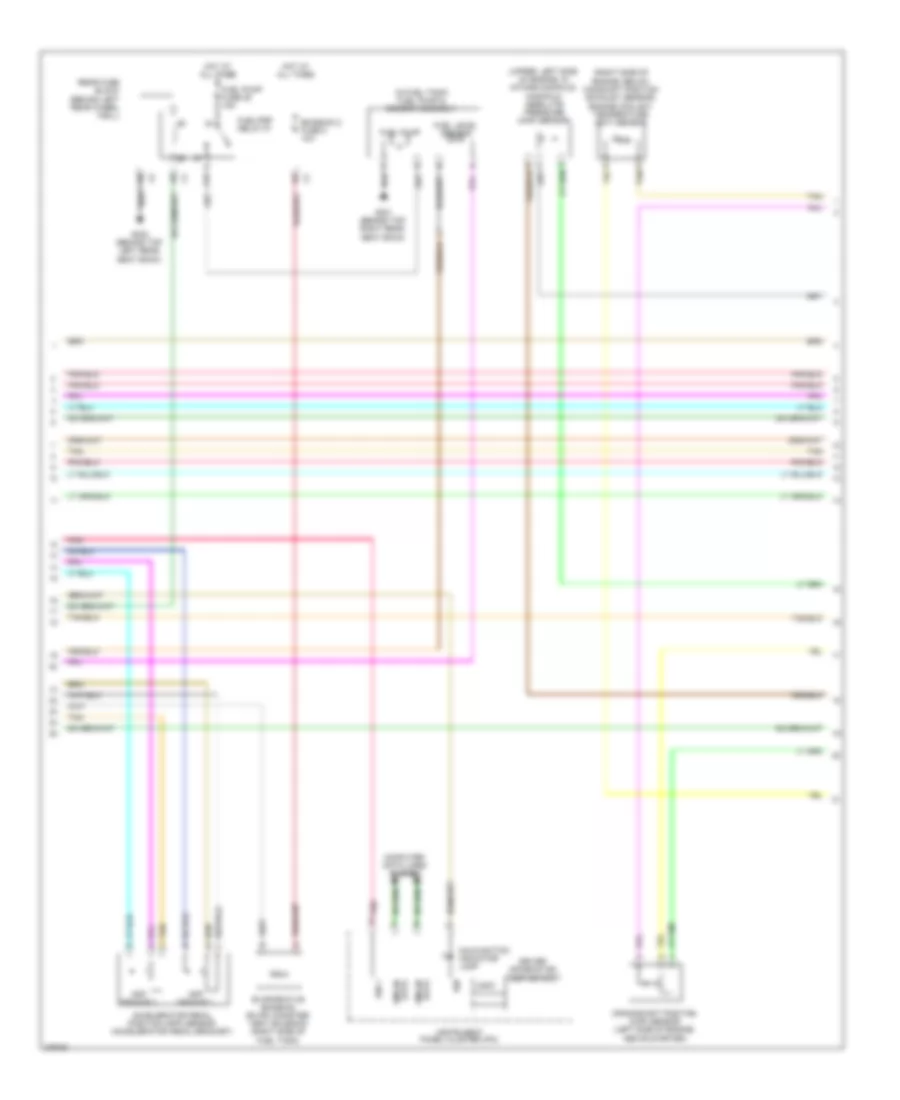
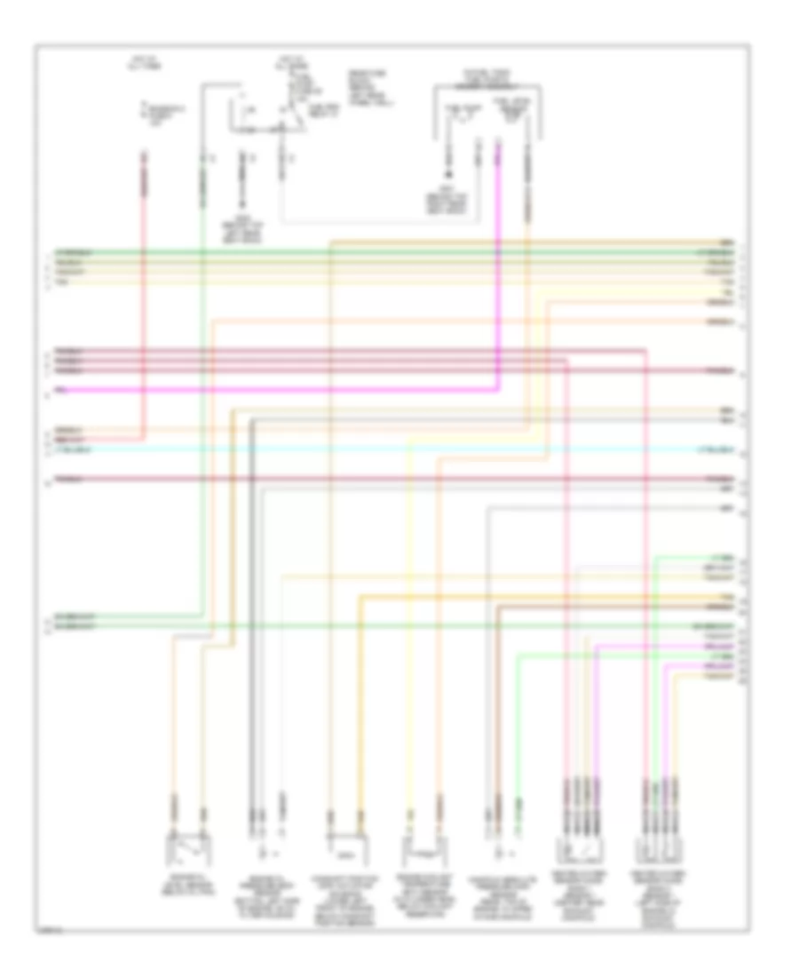
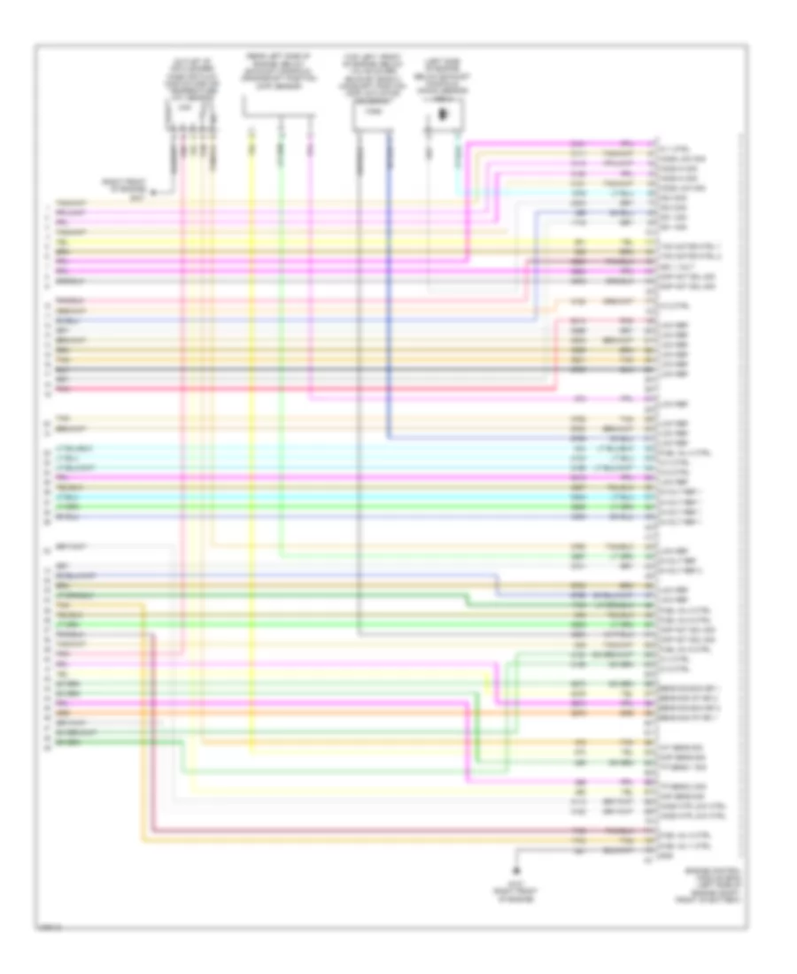
2.4L VIN 5, Engine Controls Wiring Diagram (3 of 4) for Saturn Aura XE 2008
List of elements for 2.4L VIN 5, Engine Controls Wiring Diagram (3 of 4) for Saturn Aura XE 2008:
- (in fuel tank) fuel pump & sender assembly
- (on transmission, below master cylinder) park/neutral position (pnp) switch
- (right side of engine, below camshaft position exhaust sensor) engine coolant temperature (ect) sensor
- (upper, left side of engine, in intake manifold) manifold absolute pressure (map) sensor
- 5v ref
- 5v ref 1
- 5v ref 2
- A10
- Anti-lock brakes system
- Computer data lines system
- Cooling fans system
- Ect sens sig
- Emission 2 fuse 5 10a
- Engine control module (ecm) (left side of engine compt, behind battery)
- Fan rly ctrl
- Fluid press sw sig a
- Fuel level sensor
- Fuel pump
- Fuel pump fuse 25 15a
- Fuel/pmp relay 37
- G301 (behind top right rear seat back)
- G302 (behind top left rear seat back)
- Gmlan data bus +
- Gmlan data bus -
- Hot at all times
- Low ref
- Map sens sig
- Not used) (66 to 73
- Oil press
- Park/ neutral sig
- Park/neutral sig
- Pnk
- Press sens sig
- Purge sol ctrl
- Rear fuse block (behind left rear wheel well)
- Tan
- Transmissions system
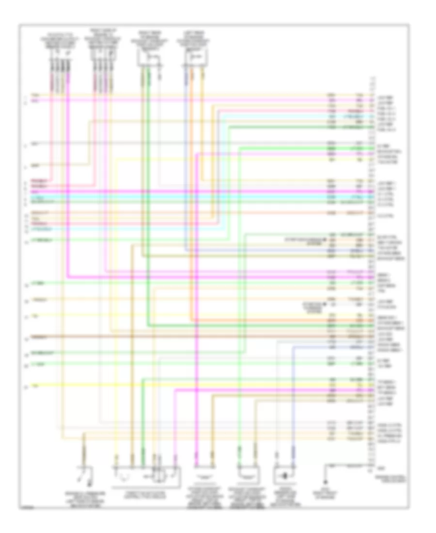
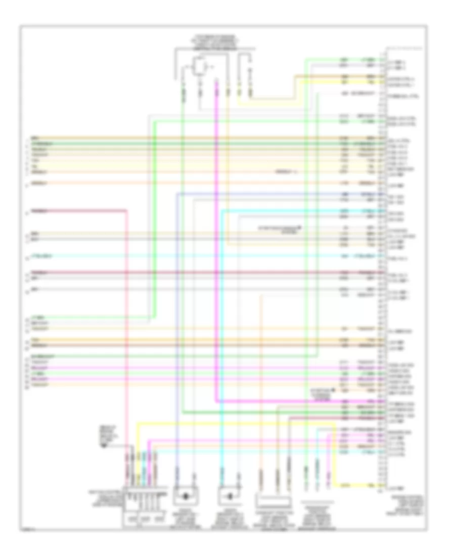
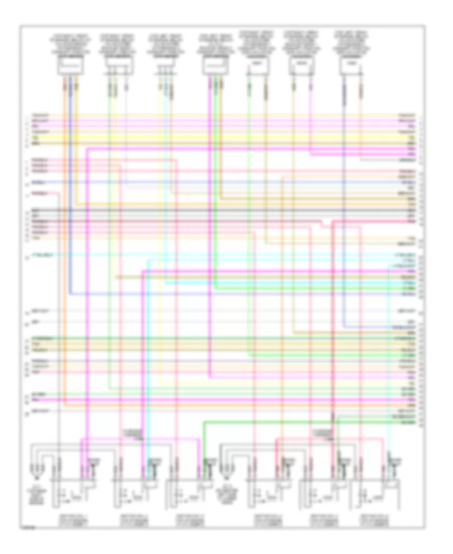
2.4L VIN 5, Engine Controls Wiring Diagram (4 of 4) for Saturn Aura XE 2008
List of elements for 2.4L VIN 5, Engine Controls Wiring Diagram (4 of 4) for Saturn Aura XE 2008:
- (in catalytic converter output) heated oxygen sensor (ho2s) 2
- (right side of engine, in exhaust manifold) heated oxygen sensor (ho2s) 1
- (upper rear, left side of engine, near camshaft cover) intake camshaft position (cmp) sensor
- (upper rear, right side of engine, near camshaft cover) exhaust camshaft position (cmp) sensor
- 5v ref
- 5v ref 1
- 5v ref 2
- Ckp sens sig
- Cmp ctrl
- Cmp sens sig
- Crankshaft position (ckp) sensor (left side of engine above starter)
- Engine control module (ecm) (left side of engine compt, behind battery)
- Engine oil pressure (eop) switch (left side of engine, above starter)
- Exhaust camshaft position (cmp) actuator solenoid (front, top of engine, between camshaft covers)
- G107 (right front of engine)
- Gnd
- Ho2s hi sig
- Ho2s lo ctrl
- Ho2s lo ref
- Ho2s lo sig
- Iat
- Iat sens sig
- Ic 1 ctrl
- Ic 2 ctrl
- Ic 3 ctrl
- Ic 4 ctrl
- Ign 1
- Inj 1 ctrl
- Inj 2 ctrl
- Inj 3 ctrl
- Inj 4 ctrl
- Intake camshaft position (cmp) actuator solenoid (front, top of engine, between camshaft covers)
- Ks sens sig
- Low ref
- Maf
- Maf sens sig
- Mass air flow (maf)/intake air temperature (iat) sensor (outlet of air cleaner)
- Nca
- Tac motor 1
- Tac motor 2
- Tan
- Tp sens 1
- Tp sens 2
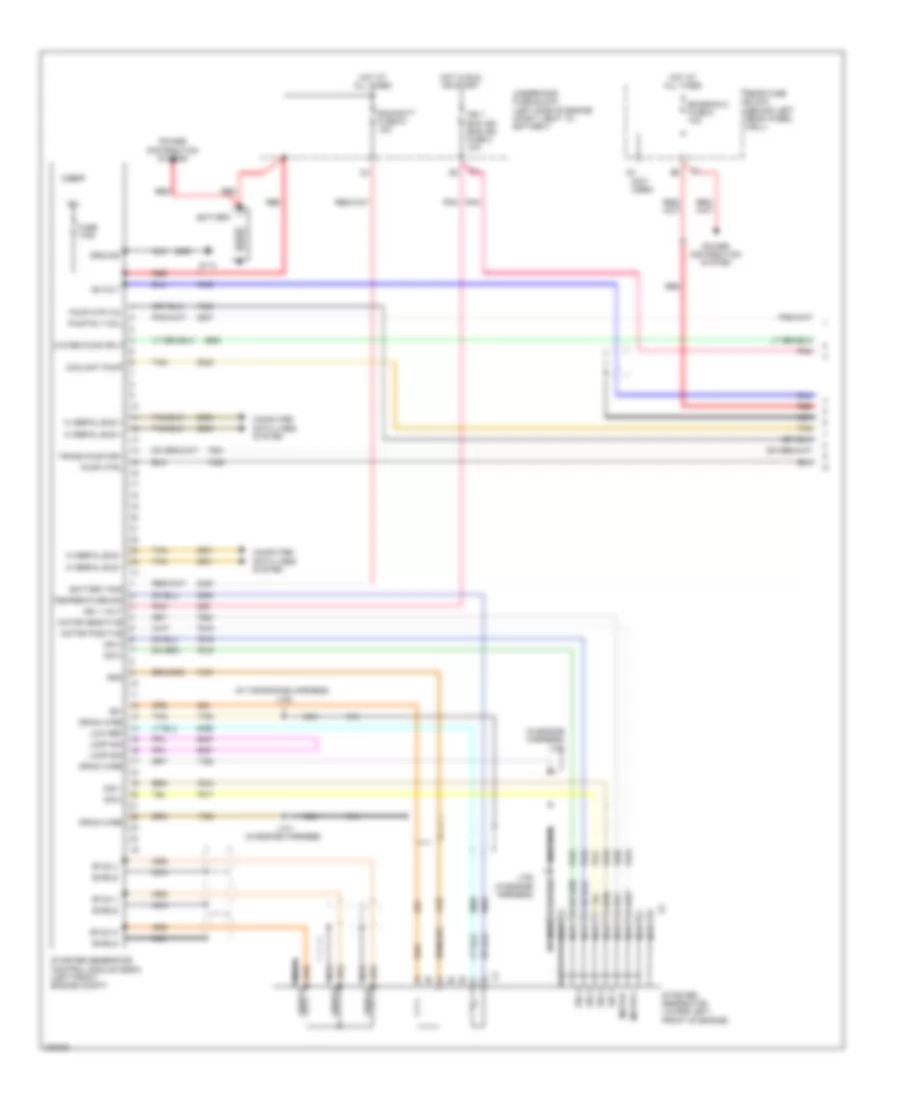
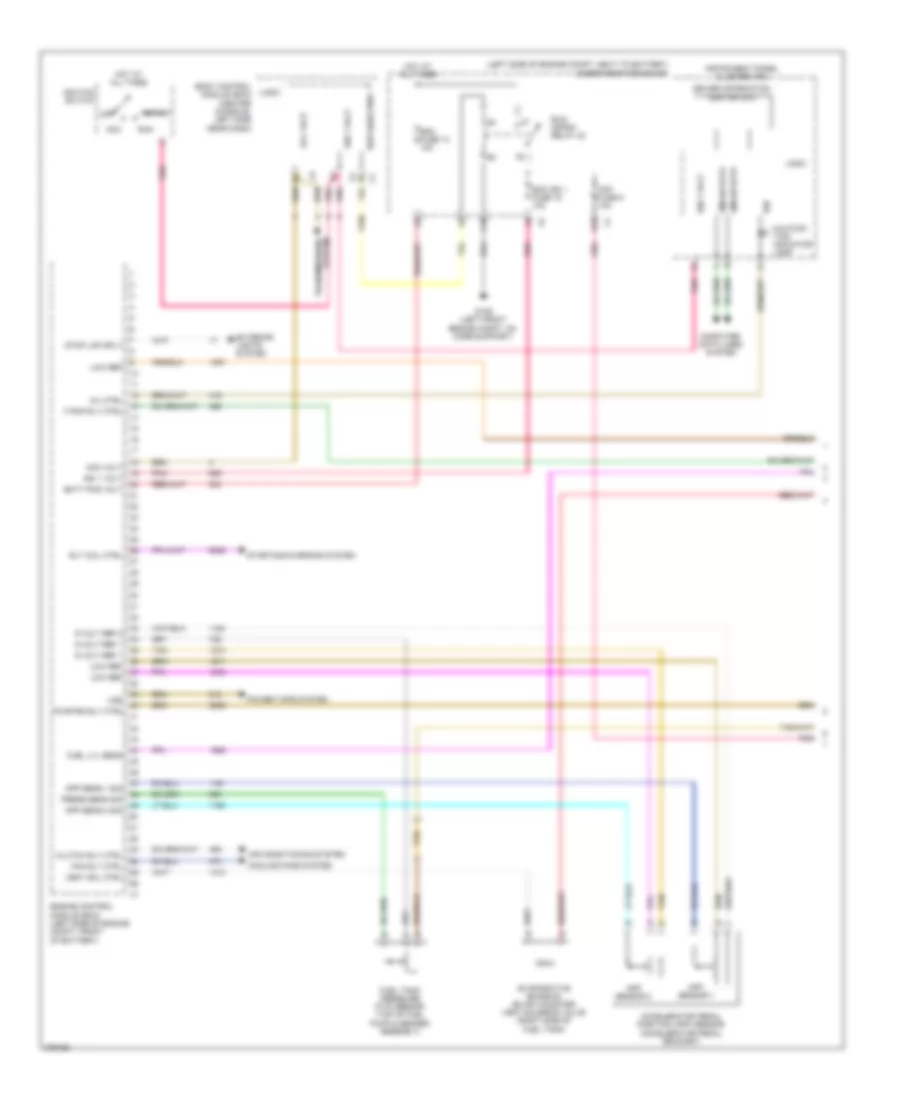
2.4L VIN 5, Hybrid System Wiring Diagram (1 of 3) for Saturn Aura XE 2008
List of elements for 2.4L VIN 5, Hybrid System Wiring Diagram (1 of 3) for Saturn Aura XE 2008:
- (in engine harness) j103
- (in the engine harness) j102
- (not used)
- 12v
- 36-volt
- 36v
- Bas batt fuse 51 10a
- Battery
- Battery pos
- Computer data lines system
- Coolant pump
- Drain wire
- Emission 2 fuse 5 10a
- Fuse 175a
- G114
- Gnd
- Ground
- Hi serial bus +
- Hi serial bus -
- Hot at all times
- Hot in run or start
- Ign 1 ecm ign bas ign fuse 3 10a
- Ign 1 volt
- J101 (in engine harness)
- J105 (in engine harness)
- Logic
- Loop sig
- Low ref
- Motor +
- Motor -
- Motor positive
- Nca
- Pnk
- Power distribution system
- Pump ctrl
- Pump mtr vol
- Pump rly coil
- Rear fuse block (behind left rear wheel well)
- Red
- Shield
- Sig 1
- Sig 2
- Sig 3
- Sig 4
- Starter generator (lower left, front of engine)
- Starter generator control module (sgcm) (left front engine compt)
- Stud u
- Stud v
- Stud w
- Tan
- Temperature sig
- Trans pump drv
- Underhood fuse block (left side of engine compt, next to battery)
- Water pump sply
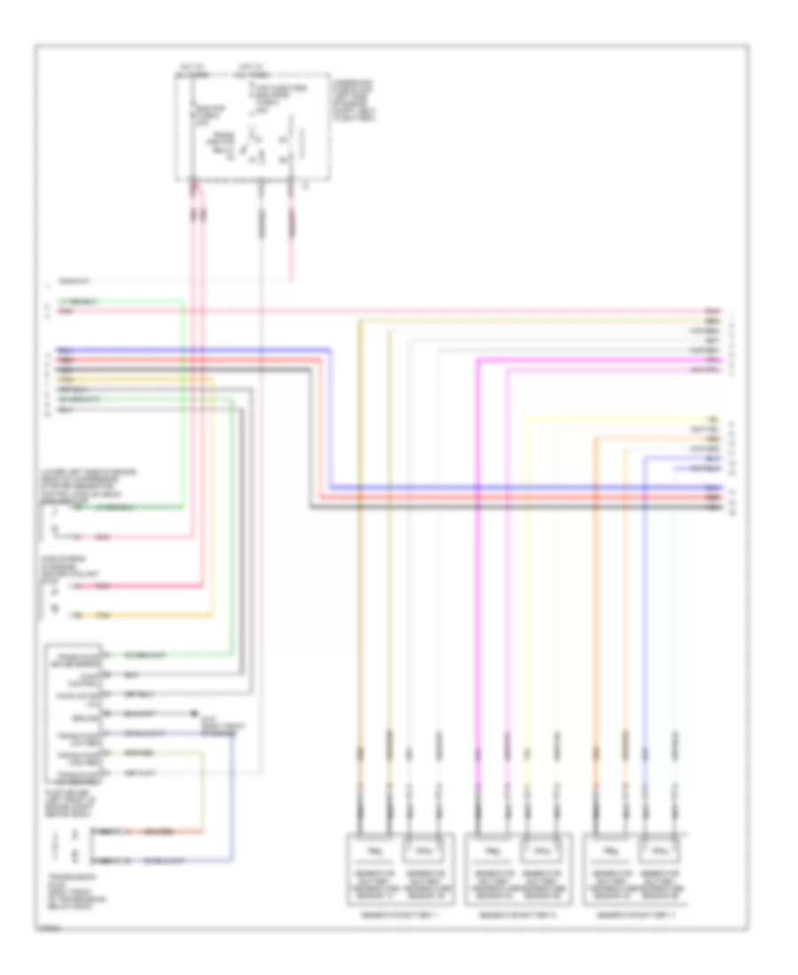
2.4L VIN 5, Hybrid System Wiring Diagram (2 of 3) for Saturn Aura XE 2008
List of elements for 2.4L VIN 5, Hybrid System Wiring Diagram (2 of 3) for Saturn Aura XE 2008:
- (lower left side of engine, near a/c compressor) starter generator control module (sgcm) cooling pump
- (middle rear of engine) heater coolant pump
- A trans pump driver error
- A12
- B pump control
- B10
- Bas pmp fuse 5 20a
- C pump motor vol
- C12
- F trans pump low ref
- G trans pump high ref
- G107 (right front of engine)
- Generator battery 1
- Generator battery 2
- Generator battery 3
- Generator battery temperature sensor 1a
- Generator battery temperature sensor 1b
- Generator battery temperature sensor 2a
- Generator battery temperature sensor 2b
- Generator battery temperature sensor 3a
- Generator battery temperature sensor 3b
- Ground
- H trans pump sw control
- Hot at all times
- Maf injectors bas pmps fuse 5 20a
- Nca
- Pnk
- Pump driver (left front of engine compt, behind sgcm)
- Red
- Tan
- Trans pmp mtr relay
- Transmission pump (right front of transmission, below sgcm)
- Underhood fuse block (left side of engine compt, next to battery)
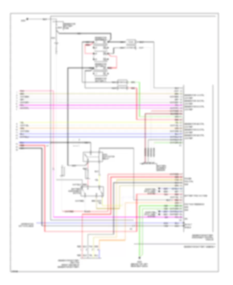
2.4L VIN 5, Hybrid System Wiring Diagram (3 of 3) for Saturn Aura XE 2008
List of elements for 2.4L VIN 5, Hybrid System Wiring Diagram (3 of 3) for Saturn Aura XE 2008:
- 200a
- 36-volt
- Battery current sensor
- Battery disconnect switch
- Battery pos voltage
- Computer data lines system
- Fan ctrl
- Fan tach feedback
- G302 (behind top left rear seat back)
- G402
- Generator 1a ctrl
- Generator 1b ctrl
- Generator 2a ctrl
- Generator 2b ctrl
- Generator 3a ctrl
- Generator 3b ctrl
- Generator battery 1
- Generator battery 2
- Generator battery 3
- Generator battery assembly
- Generator battery disconnect control module
- Generator battery fuse
- Generator battery vent fan (front center of generator battery)
- Gnd
- Ign
- Information not available
- J410
- Low ref
- Main contactor relay
- Nca
- Pnk
- Power
- Red
- Shield
- Tan
2.4L VIN B
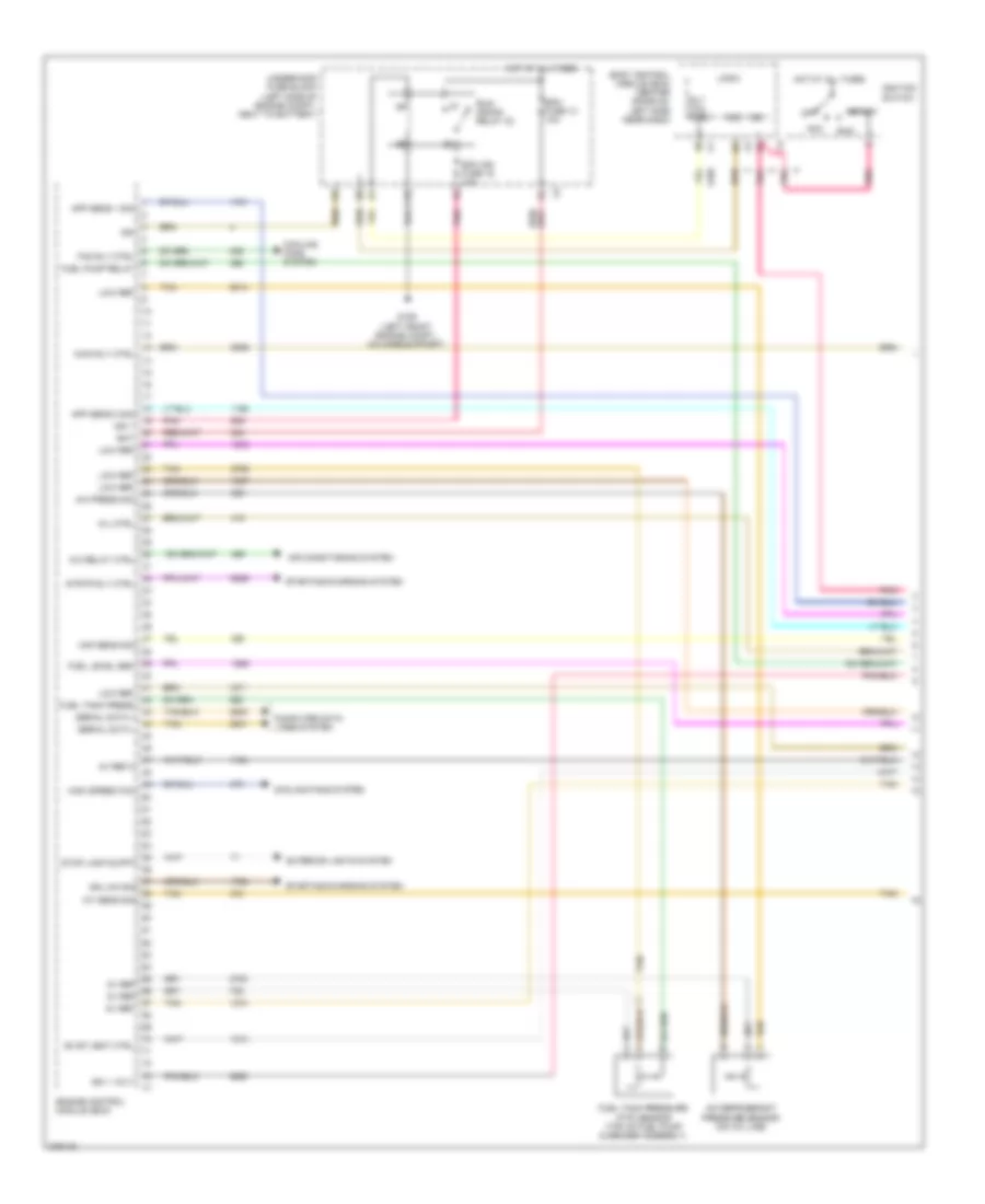
2.4L VIN B, Engine Performance Wiring Diagram (1 of 4) for Saturn Aura XE 2008
List of elements for 2.4L VIN B, Engine Performance Wiring Diagram (1 of 4) for Saturn Aura XE 2008:
- 5v ref
- 5v ref 2
- A/c press sig
- A/c refrigerant pressure sensor (on a/c line)
- A/c relay ctrl
- Acc
- Air conditioning system
- App sens 1 sig
- App sens 2 sig
- Bat
- Body control module (bcm) (center console, left side near dash)
- C10
- Computer data lines system
- Cooling fans system
- Ecm fuse 13 10a
- Ecm ign fuse 16 10a
- Engine control module (ecm)
- Evap vent ctrl
- Exterior lights system
- Fan rly ctrl
- Fuel level sen
- Fuel pump relay
- Fuel tank press
- Fuel tank pressure (ftp) sensor (top of fuel pump & sender assembly)
- G109 (left front engine compt, on core support)
- High speed fan
- Hot at all times
- Iat sens sig
- Ign
- Ign 1
- Ign 1 volt
- Ign lck sig
- Ignition switch
- Logic
- Low ref
- Maf sens sig
- Main rly ctrl
- Mil ctrl
- Off
- Pnk
- Rly coil ctrl
- Run
- Run/ crank relay 32
- Serial data +
- Serial data -
- Start
- Starting/charging system
- Stop lamp suppy
- Strtr rly ctrl
- Tan
- Underhood fuse block (left side of engine compt, next to battery)
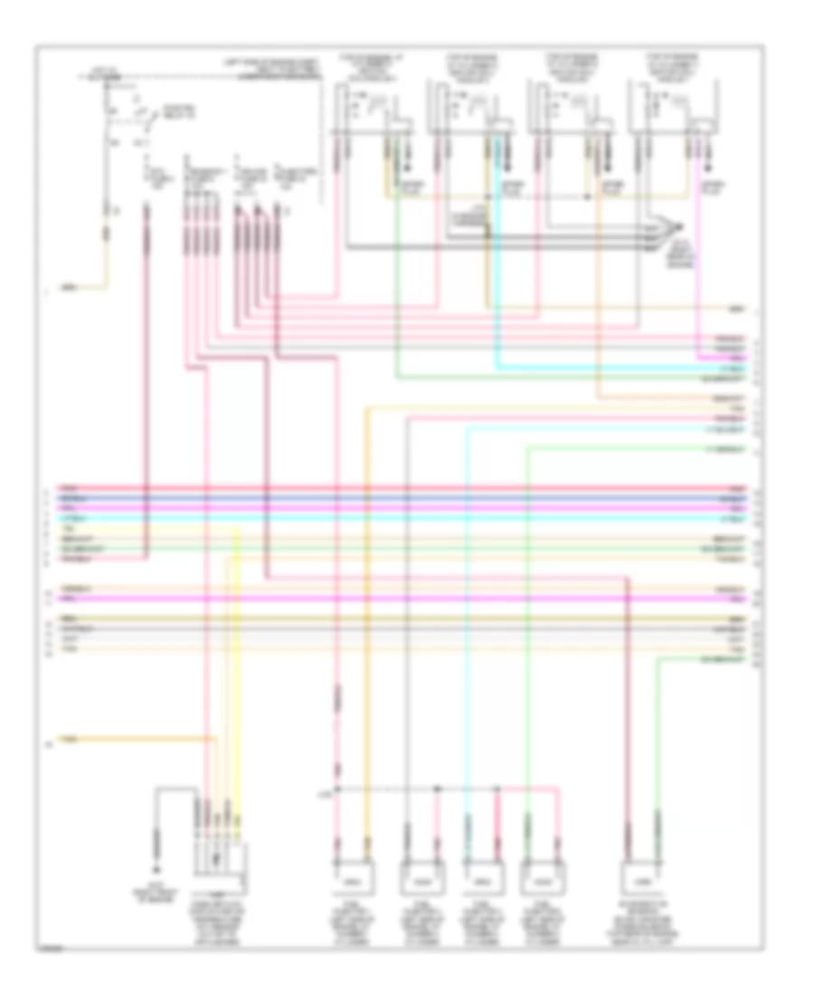
2.4L VIN B, Engine Performance Wiring Diagram (2 of 4) for Saturn Aura XE 2008
List of elements for 2.4L VIN B, Engine Performance Wiring Diagram (2 of 4) for Saturn Aura XE 2008:
- (left side of engine compt, next to battery) underhood fuse block
- (top of engine, at cylinder 1) ignition coil/ module 1
- (top of engine, at cylinder 2) ignition coil/ module 2
- (top of engine, at cylinder 3) ignition coil/ module 3
- (top of engine, at cylinder 4) ignition coil/module 4
- A10
- B11
- C11
- D11
- D12
- E11
- Emission 1 fuse 6 10a
- Etc fuse 2 15a
- Evaporative emission (evap) canister purge solenoid (top rear of engine, near oil fill cap)
- Fuel injector 1 (left side of engine, at number 1 cylinder)
- Fuel injector 2 (left side of engine, at number 2 cylinder)
- Fuel injector 3 (left side of engine, at number 3 cylinder)
- Fuel injector 4 (left side of engine, at number 4 cylinder)
- G107 (right front of engine)
- G110 (right rear of engine)
- Hot at all times
- Iat
- Ign mod fuse 43 15a
- Injectors fuse 44 10a
- J108
- Maf
- Mass air flow (maf)/intake air temperature (iat) sensor (outlet of air cleaner)
- Nca
- Pnk
- Pnk a
- Pwr/trn relay 33
- Spark plug
- Tan
- Tan b
2.4L VIN B, Engine Performance Wiring Diagram (3 of 4) for Saturn Aura XE 2008
List of elements for 2.4L VIN B, Engine Performance Wiring Diagram (3 of 4) for Saturn Aura XE 2008:
- (in fuel tank) fuel pump & sender assembly
- (right side of engine, below camshaft position exhaust sensor) engine coolant temperature (ect) sensor
- (upper, left side of engine, in intake manifold) manifold absolute pressure (map) sensor
- A tan
- A10
- Accelerator pedal position (app) sensor (accelerator pedal bracket)
- App sensor 1
- App sensor 2
- Computer data lines system
- Crankshaft position (ckp) sensor (left side of engine, above starter)
- Driver information center (dic)
- Emission 2 fuse 5 10a
- Evaporative emission (evap) canister vent solenoid (right side of fuel tank)
- Fuel level sensor
- Fuel pump
- Fuel pump fuse 25 15a
- Fuel/pmp relay 37
- G301 (behind top right rear seat back)
- G302 (behind top left rear seat back)
- Gmlan data
- Hot at all times
- Ign
- Ign 1
- Instrument panel cluster (ipc)
- Logic
- Malfunction indicator lamp
- Pnk
- Rear fuse block (behind left rear wheel well)
- Tan
2.4L VIN B, Engine Performance Wiring Diagram (4 of 4) for Saturn Aura XE 2008
List of elements for 2.4L VIN B, Engine Performance Wiring Diagram (4 of 4) for Saturn Aura XE 2008:
- (in catalytic converter output) heated oxygen sensor (ho2s) 2
- (left rear of engine) intake camshaft position (cmp) sensor 1
- (right rear of engine) exhaust camshaft position (cmp) sensor 2
- (right side of engine, in exhaust manifold) heated oxygen sensor (ho2s) 1
- 12v ref
- 5v ref
- Cycle sig
- Ect sens
- Engine control module (ecm)
- Engine oil pressure (eop) switch (left side of engine, above starter)
- Evap ctrl
- Exhaust camshaft position (cmp) actuator solenoid (front, top of engine, between camshaft covers)
- Exhaust sens
- Exhaust sol
- Fuel inj 1
- Fuel inj 2
- Fuel inj 3
- Fuel inj 4
- G107 (right front of engine)
- Gen turn sig
- Gnd
- Ho2s htr lo
- Ho2s lo ctrl
- Ic 1 ctrl
- Ic 2 ctrl
- Ic 3 ctrl
- Ic 4 ctrl
- Intake camshaft position (cmp) actuator solenoid (front, top of engine, between camshaft covers)
- Intake sens
- Intake sens 1
- Intake sol
- Knock sens
- Knock sens 1
- Knock sensor (ks) (left side of engine, above starter)
- Low ref
- Low ref 1
- Low sig
- Map sens
- Nca
- Oil press sw
- Sens 1
- Sens 2
- Sens sig 1
- Starting/ charging system
- Starting/charging system
- Tac motor
- Tan
- Tan c
- Throttle actuator control (tac) module
- Tp sens 1
- Tp sens 2
- Tps
3.5L VIN N
3.5L VIN N, Engine Performance Wiring Diagram (1 of 4) for Saturn Aura XE 2008
List of elements for 3.5L VIN N, Engine Performance Wiring Diagram (1 of 4) for Saturn Aura XE 2008:
- 5 v ref 1
- 5 v ref 2
- A/c compr rly
- A/c ref sig
- A/c refrigerant pressure sensor (on a/c line)
- Acc
- Acc vol
- Acc volt
- Accelerator pedal position (app) sensor (accelerator pedal bracket)
- Air conditioning system
- App sens 1 sig
- App sens 2 sig
- Batt pos vol
- Body control module (bcm) (center console, left side near dash)
- C10
- Computer data lines system
- Cooling fans system
- Cruise control system
- Data bus +
- Data bus -
- Ecm fuse 51 10a
- Ecm ign fuse 3 10a
- Engine control module (ecm) (left side of engine compt, front of battery)
- Evap vent
- Exterior lights system
- Fan rly ctrl
- Fuel level sens
- Fuel pump rly
- Fuel tank sig
- G107 (right front of engine)
- G109 (left front engine compt, on core support)
- Gnd
- Heated oxygen sensor (ho2s) bank 2 sensor 2 (lower front of engine compt, catalytic converter output)
- Ho2s hi sig
- Ho2s low ctrl
- Ho2s low sig
- Hot at all times
- Iat
- Iat sens sig
- Ign 1 vol
- Ign 1 volt
- Ignition switch
- Logic
- Low ref
- Maf
- Maf sens sig
- Mass air flow (maf)/intake air temperature (iat) sensor (outlet of air cleaner)
- Mil ctrl
- Nca
- Off
- Pnk
- Power distribution system
- Prk/neutral sig
- Pwr rly ctrl
- Rly coil ctrl
- Run
- Run/ crank relay 32
- Start
- Starting/charging system
- Stop lmp sig
- Tan
- Tan a
- Underhood fuse block (left side of engine compt, next to battery)
- Vss
3.5L VIN N, Engine Performance Wiring Diagram (2 of 4) for Saturn Aura XE 2008
List of elements for 3.5L VIN N, Engine Performance Wiring Diagram (2 of 4) for Saturn Aura XE 2008:
- (left side of engine compt, next to battery) underhood fuse block
- (left, top of engine, at number 4 cylinder intake port) fuel injector 4
- (left, top of engine, at number 5 cylinder intake port) fuel injector 5
- (left, top of engine, at number 6 cylinder intake port) fuel injector 6
- (right, top of engine, at number 1 cylinder intake port) fuel injector 1
- (right, top of engine, at number 2 cylinder intake port) fuel injector 2
- (right, top of engine, at number 3 cylinder intake port) fuel injector 3
- A10
- B11
- C11
- Computer data lines system
- D11
- Driver information center (dic)
- Emission 1 fuse 6 10a
- Etc fuse 2 15a
- Evaporative emission (evap) canister purge solenoid valve (top rear of engine, (on intake manifold)
- Evaporative emission (evap) canister vent solenoid valve (right side of fuel tank)
- Fuel tank pressure (ftp) sensor (top of fuel pump & sender assembly)
- Gmlan data
- Heated oxygen sensor (ho2s) bank 1 sensor 2 (in outlet of catalytic converter)
- Hot at all times
- Ign
- Ign 1 volt
- Ign mod fuse 43 15a
- Injectors fuse 44 10a
- Instrument panel cluster (ipc)
- J130 (in fuel injector harness, on main branch between fuel injector 3 breakout & fuel injector 2 breakout)
- Logic
- Malfunction indicator lamp
- Nca
- Pnk
- Post o2 fuse 45 10a
- Pwr/trn relay 33
- Tan
3.5L VIN N, Engine Performance Wiring Diagram (3 of 4) for Saturn Aura XE 2008
List of elements for 3.5L VIN N, Engine Performance Wiring Diagram (3 of 4) for Saturn Aura XE 2008:
- (in fuel tank) fuel pump & sender assembly
- A10
- Camshaft position (cmp) actuator solenoid (lower left front of engine, below camshaft position sensor)
- Emission 2 fuse 5 10a
- Engine coolant temperature (ect) sensor (in cylinder head, below coolant reservoir)
- Engine oil level sensor (below oil pan)
- Engine oil pressure (eop) sensor (bottom, left side of engine, on oil filter housing)
- Fuel level sensor
- Fuel pump
- Fuel pump fuse 25 15a
- Fuel/pmp relay 37
- G301 (behind top right rear seat back)
- G302 (behind top left rear seat back)
- Heated oxygen sensor (ho2s) bank 1 sensor 1 (center, rear exhaust manifold)
- Heated oxygen sensor (ho2s) bank 2 sensor 1 (left side of engine, in exhaust manifold)
- Hot at all times
- Manifold absolute pressure (map) sensor (rear, top of engine, in upper intake manifold)
- Nca
- Rear fuse block (behind left rear wheel well)
- Tan
3.5L VIN N, Engine Performance Wiring Diagram (4 of 4) for Saturn Aura XE 2008
List of elements for 3.5L VIN N, Engine Performance Wiring Diagram (4 of 4) for Saturn Aura XE 2008:
- (rear of engine, above oil filter) g106
- (top rear of engine, on throttle assembly) throttle actuator control (tac) module
- 5 v ref 2
- 5 vol ref 1
- Camshaft position (cmp) sensor (top, front of engine, above timing chain cover)
- Cmp sens sig
- Crankshaft position (ckp) sensor (right side of engine, below exhaust manifold)
- Cycle sig
- Ect sens sig
- Eng spd sig
- Engine control module (ecm) (left side of engine compt, front of battery)
- Fuel inj 1
- Fuel inj 2
- Fuel inj 3
- Fuel inj 4
- Fuel inj 5
- Fuel inj 6
- Gen turn on
- Gnd
- Ho2s hi sig
- Ho2s low ctrl
- Ho2s low sig
- Ic 1 ctrl
- Ic 2 ctrl
- Ic 3 ctrl
- Ic1 ctrl
- Ic2 ctrl
- Ic3 ctrl
- Ign
- Ignition control module (icm) (upper right side of engine)
- Knock sensor (ks) 1 (left side of engine, above starter)
- Knock sensor (ks) 2 (right side of engine, below exhaust manifold)
- Ks 1 sig
- Ks 2 sig
- Logic
- Low ref
- Map sen sig
- Motor ctrl 1
- Motor ctrl 2
- Oil lvl sw sig
- Oil sens sig
- Purge sol ctrl
- Sol hi ctrl
- Starting/ charging system
- Starting/charging system
- Tan
- Tan b
- Tp sens 1 sig
- Tp sens 2 sig
3.6L VIN 7
3.6L VIN 7, Engine Performance Wiring Diagram (1 of 6) for Saturn Aura XE 2008
List of elements for 3.6L VIN 7, Engine Performance Wiring Diagram (1 of 6) for Saturn Aura XE 2008:
- (left side of engine compt, next to battery) underhood fuse block
- 5-volt ref 1
- 5-volt ref 2
- Acc
- Acc volt
- Accelerator pedal position (app) sensor (accelerator pedal bracket)
- Air conditioning system
- App sens 1 sig
- App sens 2 sig
- App sensor 1
- App sensor 2
- B10
- Batt pos volt
- Body control module (bcm) (center console, left side near dash)
- C10
- Clutch rly ctrl
- Computer data lines system
- Cooling fans system
- Driver information center (dic)
- Ecm fuse 13 10a
- Ecm ign 1 fuse 16 10a
- Engine control module (ecm) (left side of engine compt, front of battery)
- Evaporative emission (evap) canister vent solenoid valve (right side of fuel tank)
- Exterior lights system
- F pmp rly ctrl
- Fan rly ctrl
- Fuel lvl sens
- Fuel tank pressure (ftp) sensor (top of fuel pump & sender assembly)
- G109 (left front engine compt, on core support)
- Gmlan data
- Hot at all times
- Ign
- Ign 1 volt
- Ignition switch
- Instrument panel cluster (ipc)
- Logic
- Low ref
- Maf fuse 5 10a
- Malfunc- tion indicator lamp
- Mil ctrl
- Off
- Pnk
- Power tops system
- Press sens sig
- Pwrtrn rly ctrl
- Rly coil ctrl
- Run
- Run/ crank relay 32
- Start
- Starting/charging system
- Stop lmp sply
- Tan
- Transmissions system
- Vent sol ctrl
- Vss
3.6L VIN 7, Engine Performance Wiring Diagram (2 of 6) for Saturn Aura XE 2008
List of elements for 3.6L VIN 7, Engine Performance Wiring Diagram (2 of 6) for Saturn Aura XE 2008:
- (center, left exhaust manifold) heated oxygen sensor (ho2s) bank 2 sensor 1
- (front of intake manifold) intake manifold tuning (imt) valve solenoid
- (left side of engine compt, next to battery) underhood fuse block
- A/c refrigerant pressure sensor (on a/c line)
- A10
- B11
- C11
- Ctrl c
- D11
- Emission 1 fuse 6 10a
- Etc fuse 2 15a
- Evaporative emission (evap) canister purge solenoid valve (top of engine, on right intake manifold)
- Fuel injector 1 (front, top of engine, at number 1 cylinder intake port)
- Fuel injector 2 (front, top of engine, at number 2 cylinder intake port)
- Fuel injector 3 (center, top of engine, at number 3 cylinder intake port)
- Fuel injector 4 (center, top of engine, at number 4 cylinder intake port)
- Fuel injector 5 (rear, top of engine, at number 5 cylinder intake port)
- Fuel injector 6 (rear, top of engine, at number 6 cylinder intake port)
- G107 (right front of engine)
- Gnd b
- Hot at all times
- Ign a
- Inj/coil even fuse 44 15a
- Inj/coil odd fuse 43 15a
- J107
- J114
- Nca
- Pnk
- Post o2 fuse 45 10a
- Pwr/trn relay 33
- Sig d
- Tan
3.6L VIN 7, Engine Performance Wiring Diagram (3 of 6) for Saturn Aura XE 2008
List of elements for 3.6L VIN 7, Engine Performance Wiring Diagram (3 of 6) for Saturn Aura XE 2008:
- (in fuel tank) fuel pump & sender assembly
- (left side of engine, behind generator) engine coolant temperature (ect) sensor
- (top center rear of engine) manifold absolute pressure (map) sensor
- 5-volt ref 1
- A/c press sens sig
- A10
- Computer data lines system
- Cooling fans system
- Duty cycle sig
- Ect sens sig
- Emission 2 fuse 5 10a
- Engine control module (ecm) (left side of engine compt, front of battery)
- Fan rly ctrl
- Fuel level sensor
- Fuel pump
- Fuel pump fuse 25 15a
- Fuel/pmp relay 37
- G301 (behind top right rear seat back)
- G302 (behind top left rear seat back)
- Gen turn on sig
- Gmlan data bus +
- Gmlan data bus -
- Ho2s hi sig
- Ho2s htr low ctrl
- Ho2s low ref
- Ho2s low sig
- Hot at all times
- Imt valve ctrl
- Low ref
- Park/neutral sig
- Pnk
- Purge sol ctrl
- Rear fuse block (behind left rear wheel well)
- Starting/ charging system
- Tan
3.6L VIN 7, Engine Performance Wiring Diagram (4 of 6) for Saturn Aura XE 2008
List of elements for 3.6L VIN 7, Engine Performance Wiring Diagram (4 of 6) for Saturn Aura XE 2008:
- (center, right exhaust manifold) heated oxygen sensor (ho2s) bank 1 sensor 1
- (engine compt rear, catalytic converter output) heated oxygen sensor (ho2s) bank 1 sensor 2
- (lower front engine compt, catalytic converter output) heated oxygen sensor (ho2s) bank 2 sensor 2
- (lower front, left side of engine) engine oil pressure (eop) switch
- Engine control module (ecm) (left side of engine compt, front of battery)
- Imt valve sig
- Knock sensor (ks) 1 (right side of engine, below exhaust manifold)
- Map sens sig
- Nca
- Oil press sw sig
- Park neutral sig
- Pnk
- Tan
- Throttle actuator control (tac) module (top rear of engine, on throttle assembly)
- Transmission control module (tcm) (inboard side, left front frame rail extension)
3.6L VIN 7, Engine Performance Wiring Diagram (5 of 6) for Saturn Aura XE 2008
List of elements for 3.6L VIN 7, Engine Performance Wiring Diagram (5 of 6) for Saturn Aura XE 2008:
- (in engine harness) j198
- (in engine harness) j199
- (top left, front of engine, below oil fill) exhaust bank 2 camshaft position (cmp) sensor
- (top left, front of engine, below valve cover) intake bank 2 camshaft position (cmp) actuator solenoid
- (top left, front of engine, below valve cover) intake bank 2 camshaft position (cmp) sensor
- (top right, front of engine, below imt valve solenoid) intake bank 1 camshaft position (cmp) sensor
- (top right, front of engine, below valve cover) exhaust bank 1 camshaft position (cmp) actuator solenoid
- (top right, front of engine, below valve cover) exhaust bank 1 camshaft position (cmp) sensor
- (top right, front of engine, below valve cover) intake bank 1 camshaft position (cmp) actuator solenoid
- G111 (top rear right side of engine)
- G113 (on center left side cylinder head)
- Ignition coil 1 (top of engine, at cylinder 1)
- Ignition coil 2 (top of engine, at cylinder 2)
- Ignition coil 3 (top of engine, at cylinder 3)
- Ignition coil 4 (top of engine, at cylinder 4)
- Ignition coil 5 (top of engine, at cylinder 5)
- Ignition coil 6 (top of engine, at cylinder 6)
- Nca
- Pnk
- Pnk b
- Spark plug
- Tan
3.6L VIN 7, Engine Performance Wiring Diagram (6 of 6) for Saturn Aura XE 2008
List of elements for 3.6L VIN 7, Engine Performance Wiring Diagram (6 of 6) for Saturn Aura XE 2008:
- (left side of engine, below exhaust manifold) knock sensor (ks) 2
- (outlet of air cleaner) mass air flow (maf)/intake air temperature (iat) sensor
- (rear left side of engine, below exhaust manifold) crankshaft position (ckp) sensor
- (right front of engine)
- (top left, front of engine, below valve cover) exhaust bank 2 camshaft position (cmp) actuator solenoid
- 5-volt ref
- 5-volt ref 1
- 5-volt ref 2
- Ckp sens sig
- Cmp act sol sig
- Engine control module (ecm) (left side of engine compt, front of battery)
- Fuel inj 1 ctrl
- Fuel inj 2 ctrl
- Fuel inj 3 ctrl
- Fuel inj 4 ctrl
- Fuel inj 5 ctrl
- Fuel inj 6 ctrl
- G107
- G107 (right front of engine)
- Gnd
- Ho2s hi sig
- Ho2s htr low ctrl
- Ho2s low sig
- Iat
- Iat sens sig
- Ic 1 ctrl
- Ic 2 ctrl
- Ic 3 ctrl
- Ic 4 ctrl
- Ic 5 ctrl
- Ic 6 ctrl
- Ign 1 volt
- Ks 1 sig
- Ks 2 sig
- Low ref
- Maf
- Maf sens sig
- Pnk
- Sens sig exh bk 1
- Sens sig exh bk 2
- Sens sig int bk 1
- Sens sig int bk 2
- Tac motor ctrl 1
- Tac motor ctrl 2
- Tan
- Tp sens 1 sig
- Tp sens 2 sig