ENGINE PERFORMANCE
2.0L VIN P
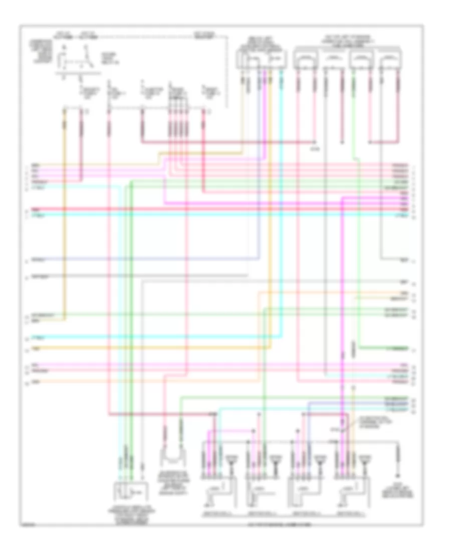
2.0L VIN P, Engine Performance Wiring Diagram (1 of 4) for Saturn Ion Red Line 2005

List of elements for 2.0L VIN P, Engine Performance Wiring Diagram (1 of 4) for Saturn Ion Red Line 2005:
- (at lower center of dash)
- (left side of engine compt) electronic brake control module (ebcm)
- +5v
- +5v ref
- A/c refrigerant pressure sensor (lower left side of engine, below generator)
- A10
- Acc
- Acc volt
- Accy
- Air conditioning system
- App sens 1 sig
- App sens 2 sig
- Battery
- Body control module (bcm)
- Class 2 data
- Clu rly ctrl
- Clutch pedal position (cpp) switch (below left side of dash)
- Computer data lines system
- Cooling fans system
- Cpp sw sig
- Cruise control system
- Cruise sig
- Data class 2
- Ecm fuse 1 10a
- Ecm fuse 13 10a
- Evap sol ctrl
- Evaporative emission canister vent solenoid
- F pmp rly ctrl
- Fan rly ctrl
- Fuel pres sig
- Fuel tank pressure (ftp) sensor (inside fuel tank)
- G101 (behind left front headlamp)
- Hi rly ctrl
- Hot at all times
- Hot in run or start
- Iat2 sig
- Ign sw fuse 1 2a
- Ign1
- Ignition switch
- Instrument cluster
- Load ctrl
- Lock
- Logic
- Low ref
- Main rly ctrl
- Malfunc- tion indicator lamp
- Mil ctrl
- Off
- Pnk
- Pnp clu st sw
- Powertrain control module (pcm) (at rear of engine, near coolant overflow container)
- Red/pnk
- Refrig pres sig
- Rly coil ctrl
- Rly ctrl
- Run
- Run/ crank relay 28
- Run/crank fuse 38 30a k1
- S101
- Sens sig pri
- Serial data
- Start
- Starting/charging system
- Stop lp sig
- Tan
- Tcc brk sw
- Underhood fuse block (left rear side of engine compt)
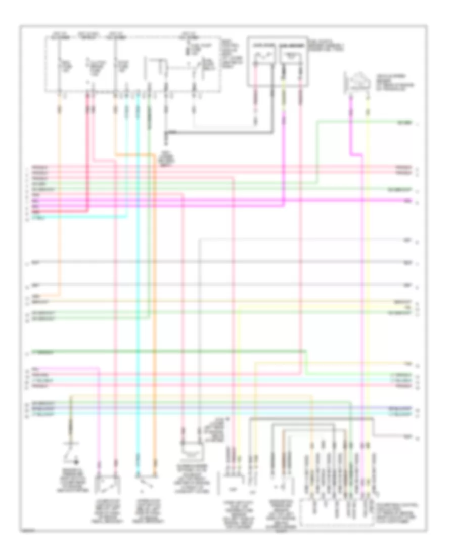
2.0L VIN P, Engine Performance Wiring Diagram (2 of 4) for Saturn Ion Red Line 2005
List of elements for 2.0L VIN P, Engine Performance Wiring Diagram (2 of 4) for Saturn Ion Red Line 2005:
- (below left side of dash) accelerator pedal position (app) sensor
- (in ignition coil harness, on top of engine)
- (on top left of engine, under fuel rail assembly) fuel injectors
- (on top of engine, under cover)
- Boost fuse 14 10a
- Ecm/etc fuse 9 15a
- Emiss fuse 10 15a
- Engine compt)
- Evaporative emission (evap) canister purge solenoid (left side of
- G105 (lower left rear of engine, above starter)
- Hot at all times
- Hot in run or start
- Ign fuse 11 10a
- Ignition coil 1
- Ignition coil 2
- Ignition coil 3
- Ignition coil 4
- Injector fuse 16 10a
- Logic
- Manifold absolute pressure (map) sensor (top right front of engine, above supercharger)
- Nca
- Pnk
- Power- train relay 28
- S139
- S140
- S141
- S142
- Spark plug
- Tan
- Underhood fuse block (left rear side of engine compart)
2.0L VIN P, Engine Performance Wiring Diagram (3 of 4) for Saturn Ion Red Line 2005
List of elements for 2.0L VIN P, Engine Performance Wiring Diagram (3 of 4) for Saturn Ion Red Line 2005:
- (pins 1-14 not used)
- (pins 16-21 not used)
- (pins 23-30 not used)
- (pins 32-35 not used)
- (pins 38-43 not used)
- (pins 46-56 not used)
- +5v
- Ba1
- Ba2
- Ba3
- Ba4
- Baro sig
- Barometric pressure sensor (on top left side of engine, behind supercharger inlet)
- Bcm fuse 15a
- Body control module (bcm) (at lower center of dash)
- Clutch/ brake fuse 7.5a
- Engine oil pressure (eop) switch (lower rear of engine, above starter)
- Evap sol
- Fuel pump
- Fuel pump & sender assembly (inside fuel tank)
- Fuel pump fuse 15a
- Fuel pump relay
- Fuel sender
- G105 (lower left rear of engine, above starter)
- G301 (under driver's seat)
- Hot at all times
- Hot in acc or run
- Iat
- Low ref
- Lower stop lamp switch (below left side of dash, on brake pedal bracket)
- Maf
- Mass air flow/ inlet air temperature sensor (on left side of engine, above air cleaner)
- Nca
- Pnk
- Powertrain control module (pcm) (at rear of engine near coolant over- flow container)
- S351
- Stop fuse 15a
- Supercharger bypass valve solenoid (on top front center of engine, in front of camshaft cover)
- Sw sig
- Tan
- Upper stop lamp switch (below left side of dash, on brake pedal bracket)
- Vehicle speed sensor (at rear of engine, on transaxle)
- Vss hi
- Vss low
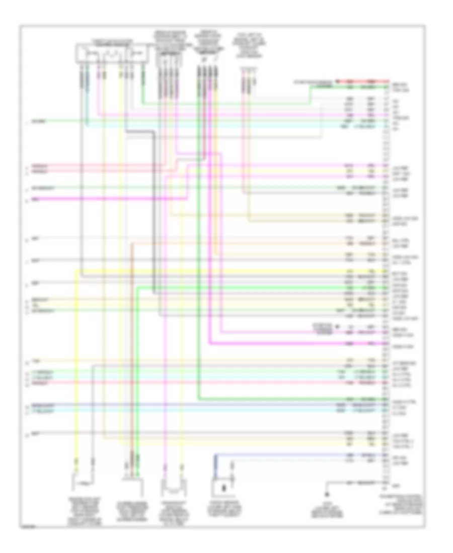
2.0L VIN P, Engine Performance Wiring Diagram (4 of 4) for Saturn Ion Red Line 2005
List of elements for 2.0L VIN P, Engine Performance Wiring Diagram (4 of 4) for Saturn Ion Red Line 2005:
- (rear of engine compartment, in exhaust near catalytic converter) heated oxygen sensor 2
- (rear of engine compt, in exhaust manifold) heated oxygen sensor 1
- (top left of engine, left of camshaft cover) camshaft position (cmp) sensor
- +5v
- A tan
- Ckp 1 sig
- Cmp sig
- Crankshaft position (ckp) sensor (lower rear of engine, below oil filter)
- Ect sig
- Engine coolant temperature (ect) sensor (top of engine, near right front corner of camshaft cover)
- G105 (lower left rear of engine, above starter)
- Gen sig
- Gnd
- Ho2s hi ctrl
- Ho2s hi sig
- Ho2s low sig
- Iat sens sig
- Ic 1 sig
- Ic 2 sig
- Ic 3 sig
- Ic4 sig
- Inj 1 ctrl
- Inj 2 ctrl
- Inj 3 ctrl
- Inj 4 ctrl
- Knock sensor (lower left side of engine, below throttle body)
- Ks1 sig
- Low ref
- Maf sig
- Map sig
- Nca
- Powertrain control module (pcm) (at rear of engine near coolant overflow container)
- Red
- Scip sig
- Sol ctrl
- Starting/ charging system
- Starting/charging system
- Supercharger inlet pressure (scip) sensor (top left of supercharger)
- Tac ctrl 1
- Tac ctrl 2
- Tan
- Throttle actuator control module
- Tps1 sig
- Tps2 sig