ENGINE PERFORMANCE
1.3L
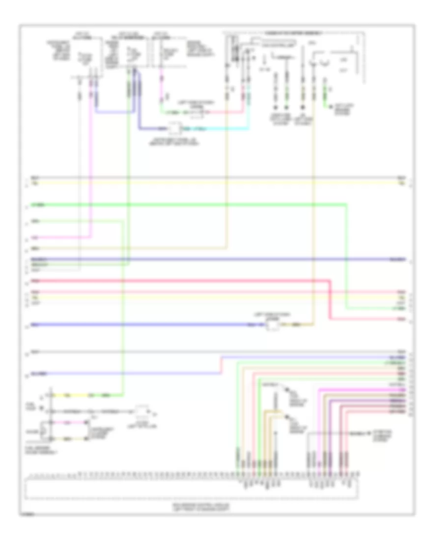
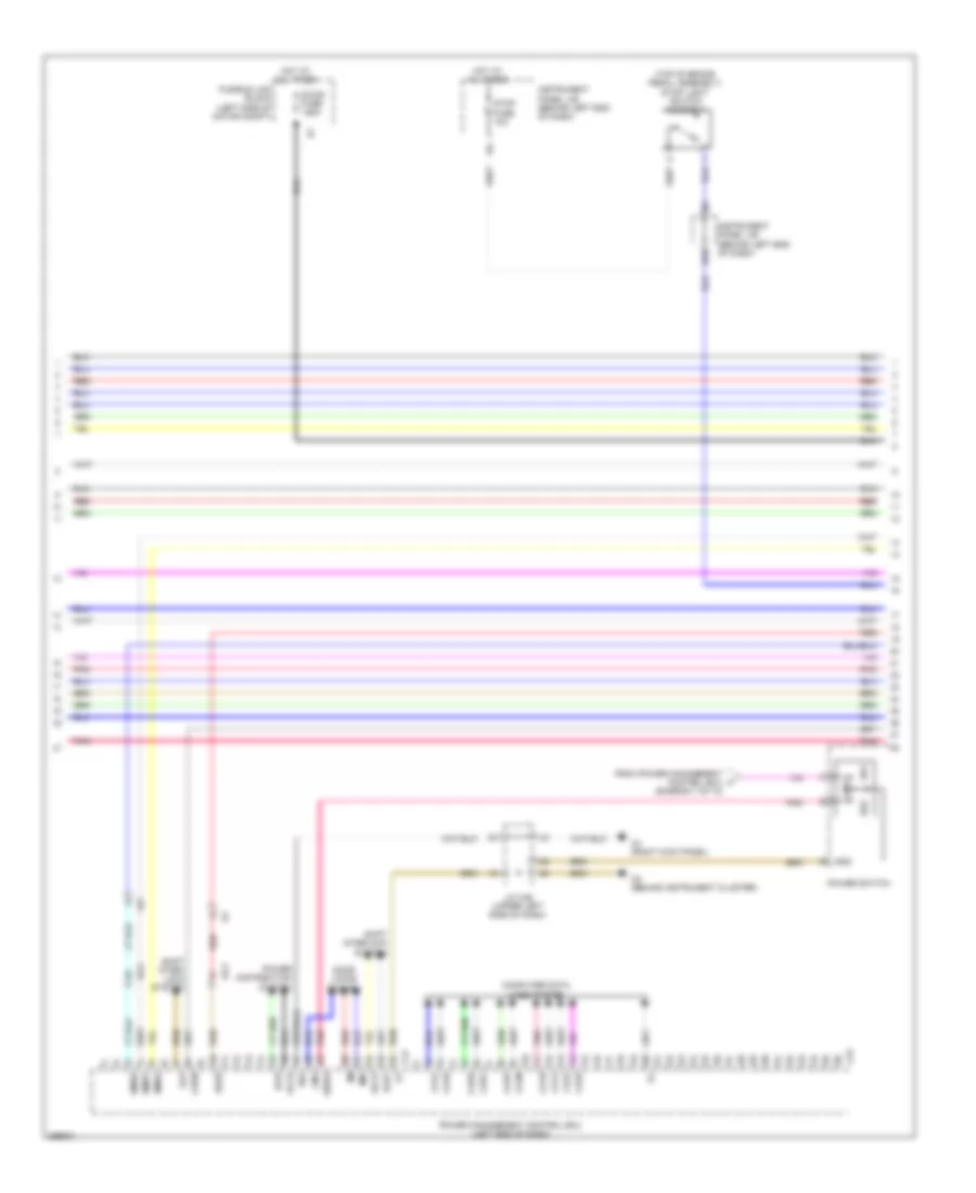
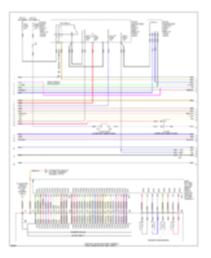
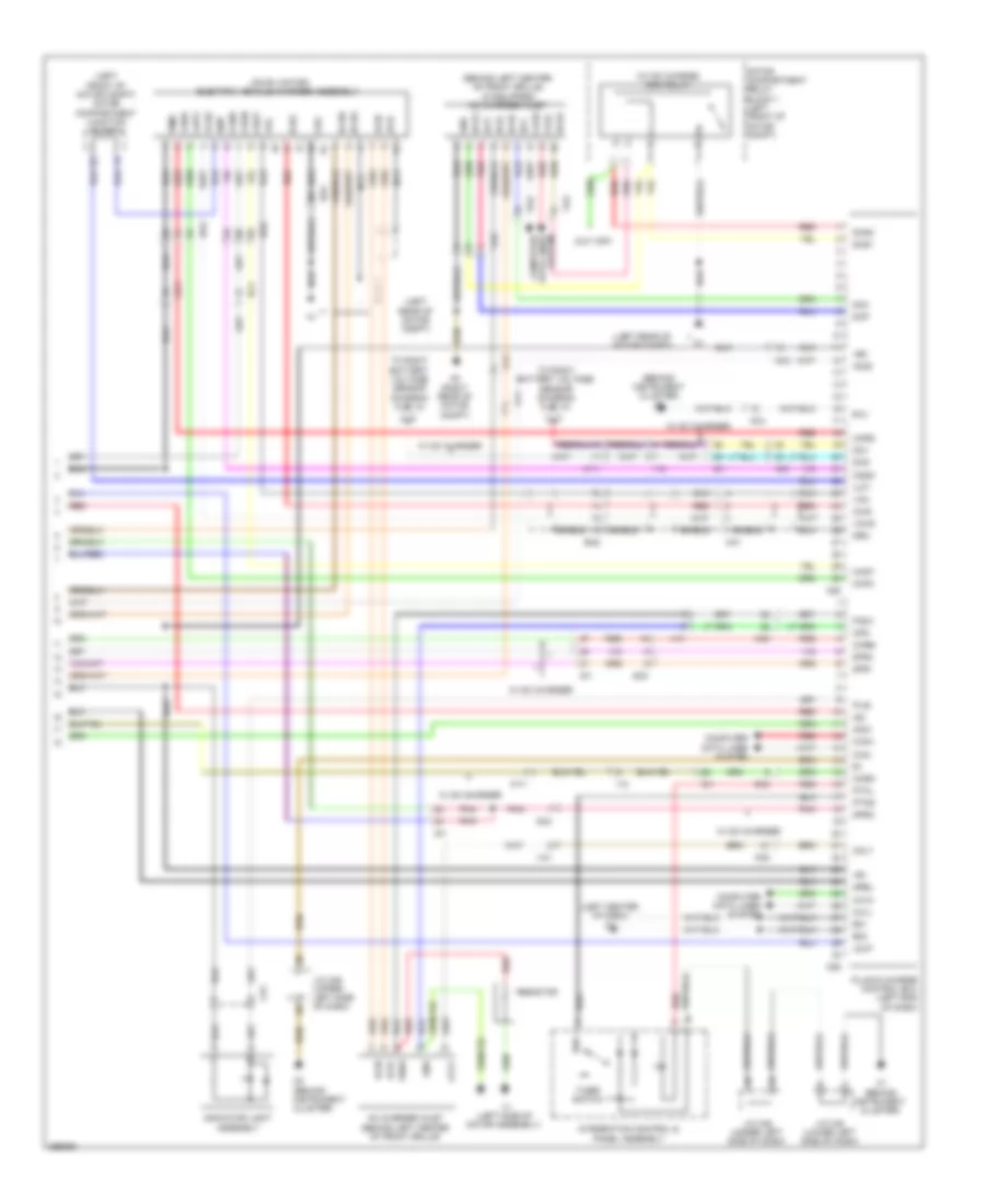
1.3L, Engine Performance Wiring Diagram (1 of 4) for Scion iQ 2013

List of elements for 1.3L, Engine Performance Wiring Diagram (1 of 4) for Scion iQ 2013:
- +b2
- +bm
- A18
- A2 (left rear of engine compt)
- Accelerator pedal sensor assembly (accelerator pedal)
- Ad4
- Ad5 starting/charging system
- Ag2
- Anti-theft system
- B10
- B12 (top front of engine)
- B35
- Ba2
- Batt
- Bc3
- C/open relay
- Canh
- Canister pump module (under left rear of vehicle)
- Canl
- Computer data lines system
- Cooling fans system
- Defogger system
- Ecm (engine control module) (left front of engine compt)
- Efi 1 fuse 10a
- Efi relay
- Efi-main fuse 20a
- Els
- Els2
- Engine room j/b 1 (left side of engine compt)
- Engine room r/b 1 (left side of engine compt)
- Epa
- Epa2
- Etcs fuse 10a
- Exterior lights system a1 (left rear of engine compt)
- F12
- Fanh
- Fanl
- Hot at all times
- Hot w/ ig2 relay energized
- Ign fuse 15a
- Igsw
- Imi
- Imo
- Instrument panel j/b (behind left end of dash)
- Mgnd
- Mpmp
- Mrel
- Mtrb
- Nsw
- Pnk
- Sdsw
- Sgnd
- Spd
- St1-
- Sta
- Starting/charging system
- Stop light switch assembly
- Stp
- Tach
- Vcc
- Vcp2
- Vcpa
- Vgnd
- Vlvb
- Vout
- Vpa
- Vpa2
- Vpmp
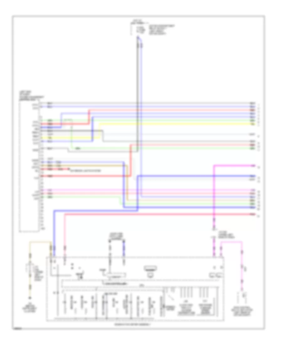
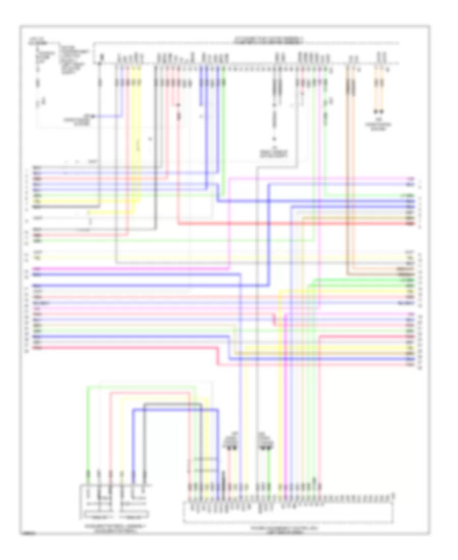
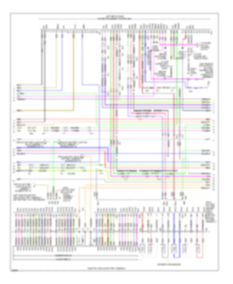
1.3L, Engine Performance Wiring Diagram (2 of 4) for Scion iQ 2013
List of elements for 1.3L, Engine Performance Wiring Diagram (2 of 4) for Scion iQ 2013:
- (left side of dash)
- 5v +b
- 5v ic
- Ad2
- Alt
- Anti-lock brakes system
- B11 (top front of engine)
- B12 (top front of engine)
- B17
- B32
- C25
- Can controller
- Can i/f
- Canh
- Canl
- Combination meter assembly
- Computer data lines system
- Cpu
- Cvt
- D10
- D6 (left side of dash)
- Ds1
- Ds2
- Dsu
- E01
- E04
- Ecm (engine control module) (left front of engine compt)
- Ecu-b 2 fuse 5a
- Efi
- Engine room j/b 1 (left side of engine compt)
- Engine room r/b 1 (left side of engine compt)
- Eo2
- Fuel pump
- Fuel sender gauge assembly
- Gauge
- Ge01
- Gl1
- Hot at all times
- Hot w/ ig2 relay energized
- I/f
- Ig+
- Ig2 fuse 10a
- Instrument cluster system
- Instrument panel j/b (behind left end of dash)
- J/c d68
- J/c g43 (left "b" pillar)
- Lcd
- Malfunction ind lamp
- Me01
- Pnk
- Red
- Sls+
- Sls-
- Starting/ charging system
- Stop fuse 10a
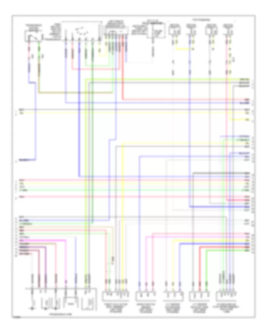
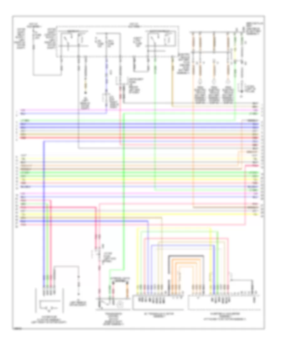
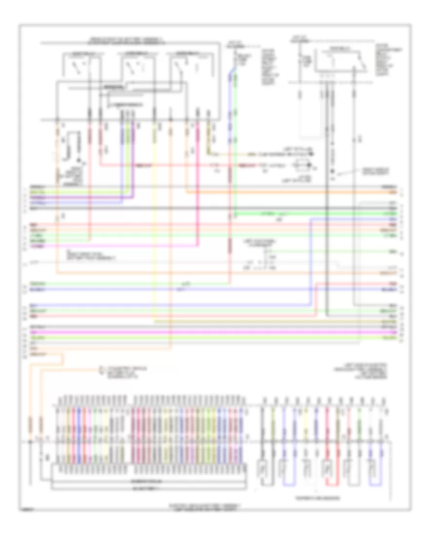
1.3L, Engine Performance Wiring Diagram (3 of 4) for Scion iQ 2013
List of elements for 1.3L, Engine Performance Wiring Diagram (3 of 4) for Scion iQ 2013:
- (left side of engine compt) engine room j/b 1
- (top of engine)
- Ad2
- Ad4
- At3
- B27
- Bc3
- Crank position sensor (left front of engine)
- Dsl
- E2g
- Gauge fuse 10a
- Hot w/ ig1 relay energized
- Igf
- Ignition coil 1
- Ignition coil 2
- Ignition coil 3
- Ignition coil 4
- Igt
- Igt2
- Igt3
- Igt4
- Instrument panel j/b (behind left end of dash)
- Intake mass air flow meter assembly (air intake tube)
- Ne+
- Ne-
- Nssd
- Park/ neutral position switch assembly (top of
- Pnk
- Red
- Slu+
- Slu-
- Tha
- Tho
- Throttle w/ motor body assembly (left side of engine)
- Transmission control switch
- Transmission wire
- Transmission)
- Vc2
- Vta
- Vta2
- Vve+
- Vve-
- Vvi+
- Vvi-
- Vvt sensor (exhaust side) (left rear of engine)
- Vvt sensor (intake side) (right rear of engine)
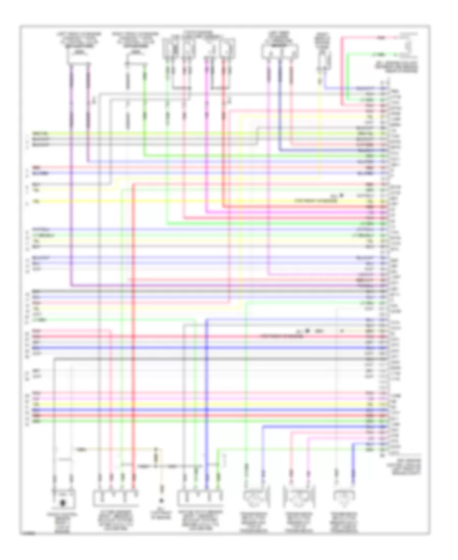
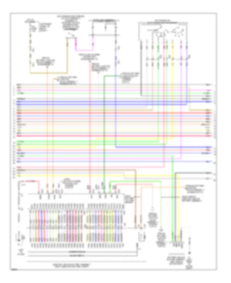
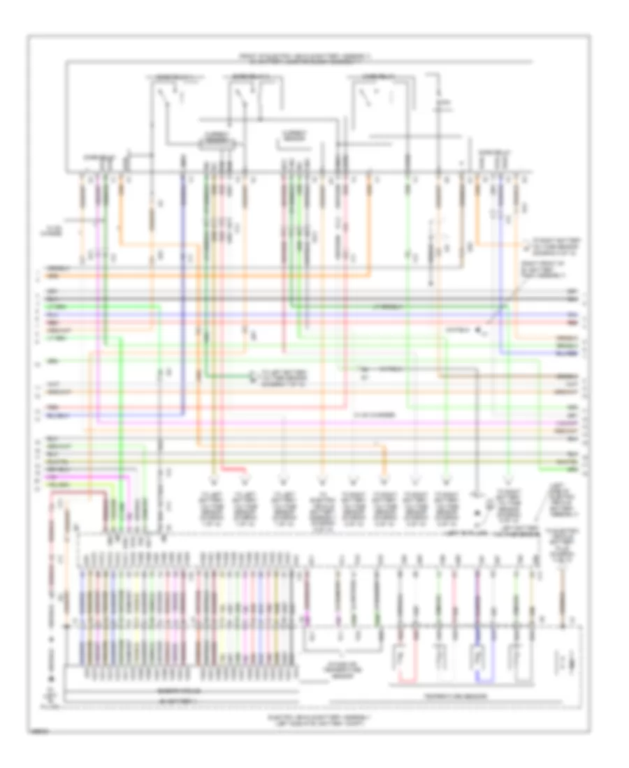
1.3L, Engine Performance Wiring Diagram (4 of 4) for Scion iQ 2013
List of elements for 1.3L, Engine Performance Wiring Diagram (4 of 4) for Scion iQ 2013:
- (left front of engine) camshaft timing oil control valve (exhaust side)
- (left rear of engine) oil pressure sensor
- (right front of engine) camshaft timing oil control valve (intake side)
- (right rear of engine) purge vsv
- (top of engine) fuel injectors assembly
- 0x1b
- A1a+
- A1a-
- Air fuel ratio sensor (bank 1 sensor 1) (exhaust system, before catalytic converter)
- B11 (top front of engine)
- B12 (top front of engine)
- Bc4
- E.f.i. engine coolant temperature sensor (rear of engine)
- E03
- E2g
- Ecm (engine control module) (left front of engine compt)
- Eknk
- Eppm
- Epto
- Eta
- Etha
- Etho
- Ethw
- Ev1+
- Ev1-
- Ex1b
- G2+
- G2-
- Ha1a
- Ht1b
- Igf1
- Igt1
- Igt2
- Igt3
- Igt4
- Knk1
- Knock control sensor (bank 1) (top of engine)
- Nca
- Ne+
- Ne-
- Nin+
- Nin-
- Notb
- Noto
- Ntb
- Nto
- Oc1+
- Oc1-
- Oe1+
- Oe1-
- Ox1b
- Oxygen sensor (bank 1 sensor 2) (exhaust system, after catalytic converter)
- Pnk
- Ppmp
- Prg
- Pto
- Red
- Tha
- Tho1
- Thw
- Transmission revolution sensor (nin) (top of transmission)
- Transmission revolution sensor (nout) (left side of transmission)
- Transmission revolution sensor (nt) (top of transmission)
- Vce1
- Vcne
- Vcpp
- Vcpt
- Vcta
- Vcv1
- Vta1
- Vta2
ELECTRIC
Electric, Engine Performance Wiring Diagram (1 of 10) for Scion iQ 2013
List of elements for Electric, Engine Performance Wiring Diagram (1 of 10) for Scion iQ 2013:
- (left end of dash) power management control ecu
- +b2
- 5v ic
- 5v+b
- A23
- Ac5
- Am2 fuse 7.5a
- Am22
- Ba2
- Buzzer
- C5 (behind instrument cluster)
- Can controller
- Can i/f
- Canh
- Canl
- Charge ind
- Clk+
- Clk-
- Clock odo/ trip cvt outside temperature
- Combination meter assembly
- Computer data lines system
- Cpu
- Eco ind
- Exterior lights system
- Hot at all times
- Htm+
- Htm-
- I/f
- Ig+
- Ilk
- Ind
- Iwp
- J/c c46 (upper left side of dash)
- Lcd
- Led driver
- Low battery ind
- Master ind
- Mmt
- Mmtg
- Motor compartment relay block 1 (left front motor compt)
- Mth+
- Mth-
- Niwp
- Nodd
- Output restriction ind
- Plug-in (green)
- Pnk
- Ready ind
- Red
- Req+
- Req-
- Skid control ecu w/ actuator (left rear of motor compt)
- Soc range average speed sensor
- Soc warning ind
- Sp1
- Speedo- meter
- Tft
- Vlo
Electric, Engine Performance Wiring Diagram (2 of 10) for Scion iQ 2013
List of elements for Electric, Engine Performance Wiring Diagram (2 of 10) for Scion iQ 2013:
- (diagram 7 of 10)
- (top of brake pedal assembly) stop light switch assembly
- Accd
- B35
- C21
- C23
- C4 (right kick panel)
- C5 (behind instrument cluster)
- Ca1h
- Ca1l
- Ca2h
- Ca2l
- Ca3n
- Ca3p
- Ca4h
- Ca4l
- Cabh
- Cabl
- Chen
- Computer data lines system
- Dc/dc fuse 125a
- Door locks system
- E01
- From power management control ecu v
- Fusible link block (left side of motor compt)
- Gc2
- Gc3
- Gnd
- Gi1
- Hot at all times
- Ig1d
- Imi
- Imo
- Instrument panel j/b (behind left end of dash)
- J/c c46 (upper left side of dash)
- Lin2
- Pnk
- Power distribution system
- Power management control ecu (left end of dash)
- Power switch
- Red
- Shift inter- lock system
- Shift interlock system
- Slck
- Slp
- Slr+
- Smrb
- Smrg
- Smrp
- Sr2b
- Ss1
- Ss2
- Ssw2
- Stop fuse 10a
Electric, Engine Performance Wiring Diagram (3 of 10) for Scion iQ 2013
List of elements for Electric, Engine Performance Wiring Diagram (3 of 10) for Scion iQ 2013:
- (attached to ev motor assembly) inverter w/ converter assembly
- +b2
- A21
- A22
- A4 (right side of motor compt)
- Accelerator pedal assembly (accelerator pedal)
- Acpb
- Acpe
- Ag1
- Air
- Air condi- tioning system
- Air conditioning system
- Amd
- Ba1
- Cbi
- Cei
- Clk
- Clk+
- Clk-
- Conditioning system
- Dc/dc-s fuse 5a
- Drn1
- Drn2
- Drn3
- Drn4
- Drn8
- Ep1
- Ep2
- Eti
- Gnd1
- Gnd2
- Hall ic
- Hot at all times
- Hsdn
- Htm+
- Htm-
- Idh
- Igct
- Ilki
- Ilko
- Ite
- Motor compartment junction block 1 (left front of motor compt)
- Mth+
- Mth-
- Nodd
- Pnk
- Power management control ecu (left end of dash)
- Red
- Req+
- Req-
- Shield
- Sio
- Stb
- Stp
- Vcp1
- Vcp2
- Vlo
- Vpa1
- Vpa2
Electric, Engine Performance Wiring Diagram (4 of 10) for Scion iQ 2013
List of elements for Electric, Engine Performance Wiring Diagram (4 of 10) for Scion iQ 2013:
- (center of ev battery assembly)
- +bwp
- A1 (left rear of motor compt)
- A2 (left rear of motor compt)
- A48
- Ac3
- At3
- B17
- Batt fan fuse 15a
- Batt fan relay
- C25
- C38
- D12
- Drn6
- Electric vehicle battery plug
- Ev transaxle w/ motor assembly
- From electric vehicle battery assembly (diagram 6 of 10)
- From electric vehicle battery assembly (diagram 8 of 10)
- From electric vehicle battery assembly (diagram 9 of 10)
- Gnd
- Gi1
- Hot at all times
- Ig2 2 fuse 5a
- Ig2 fuse 10a
- Ig2 relay
- Ilk
- Instrument panel j/b (behind left end of dash)
- Interior lights system
- Inverter w/ converter assembly (attached to ev motor assembly)
- J/c a48 & c45 (left kick panel) c45
- J/c c49 (right side of dash)
- J/c g34 (left "b" pillar)
- Mcs
- Mcsg
- Mmt
- Mmtg
- Motor compt junction block 1 (left front of motor compt)
- Motor compt relay block 1 (left front of motor compt)
- Mrf
- Mrfg
- Msn
- Msng
- Nca
- Nssd
- Nwp
- Pi fuse 30a
- Pnk
- Red
- Service plug grip (center of ev battery assembly)
- Swp
- Transmission control switch (base of shift lever assembly)
- Water pump w/ motor assembly (left front of motor compt)
- Ii1
Electric, Engine Performance Wiring Diagram (5 of 10) for Scion iQ 2013
List of elements for Electric, Engine Performance Wiring Diagram (5 of 10) for Scion iQ 2013:
- (left "b" pillar)
- (on charging port opening lid lock assembly) charger lid courtesy switch (charging port opening lid lock sub-assembly)
- (on transaxle)
- (right side of electric vehicle battery assembly)
- 80a
- A1 (left rear of motor compt)
- Ac4
- Ac5
- Am1 fuse 7.5a
- Ba1
- Ba2
- Battery cooling blower assembly (left side of motor compt)
- Block assembly 1 (diagram 9 of 10)
- Busbar module
- D28
- Dcg
- Dcv
- Dfrc
- Dfrh
- Electric vehicle battery assembly (right side of ev battery compt)
- Ev battery 5
- From ev battery junction block assembly 1 (diagram 9 of 10)
- From ev battery junction q
- From plug-in charge control ecu (diagram 10 of 10)
- Ga4
- Ga5
- Gib2
- Gnd0
- Gnd2
- Gi1
- Hot at all times
- Ib2
- Ib21
- Ig0
- Instrument panel j/b relay block 1
- J/c g34
- Oa1
- Pnk
- Pnk va48
- Red
- Red va50
- Right battery voltage sensor
- Shift lever position sensor
- Si0
- Stop light assembly
- Va46
- Va47
- Va48
- Va49
- Va50
- Va51
- Va52
- Va53
- Va54
- Va55
- Va56
- Va57
- Va58
- Va59
- Va60
- Va61
- Va62
- Va63
- Va64
- Va65
- Va66
- Va67
- Va68
- Va69
- Va70
- Va71
- Va72
- Va73
- Va74
- Va75
- Vib2
- Vm0
- W12
- W14
- W15
- W18
- W19
- Wy1
- Iy1
Electric, Engine Performance Wiring Diagram (6 of 10) for Scion iQ 2013
List of elements for Electric, Engine Performance Wiring Diagram (6 of 10) for Scion iQ 2013:
- (right side of ev battery compt)
- (right side of motor compt)
- 80a
- Ac2
- Ag1
- Ba2
- Busbar module
- C10
- C47
- C48
- Dome fuse 10a
- Electric vehicle battery assembly
- Ev battery 2
- F12
- Ga2
- Ga3
- Gb16
- Gb17
- Gb18
- Gb19
- Hot at all times
- Igct 2 fuse 10a
- Igct 3 fuse 10a
- Igct fuse 30a
- Igct relay
- Inv w/p fuse 15a
- J/c c46 (upper left side of dash)
- J/c c47 & c48 (lower left side of dash)
- Motor compartment junction block 1 (left front of motor compt)
- Motor compartment relay block 2 (right front of motor compt)
- Motor compt relay block 1 (left front of motor compt)
- Pcu fuse 20a
- Pnk
- Pnk va15
- Red
- Red va17
- Right battery voltage sensor (right side of electric vehicle battery assembly)
- Tb16
- Tb17
- Tb18
- Tb19
- Temperature sensors
- To electric vehicle battery assembly (diagram 7 of 10)
- To electric vehicle battery plug (diagram 4 of 10)
- Va13
- Va14
- Va15
- Va16
- Va17
- Va18
- Va19
- Va20
- Va21
- Va22
- Va23
- Va24
- Va25
- Va26
- Va27
- Va28
- Va29
- Va30
- Va31
- Va32
- Va33
- Va34
- Va35
- Va36
- Va37
- Va38
- Va39
- Va40
- Va41
- Va42
- Va43
- Va44
- Va45
- W14
- W16
- W17
- Ko1
Electric, Engine Performance Wiring Diagram (7 of 10) for Scion iQ 2013
List of elements for Electric, Engine Performance Wiring Diagram (7 of 10) for Scion iQ 2013:
- (behind instrument cluster) c5
- (left end of dash) power management control ecu
- (left rear of motor compt) battery temperature sensor (thermistor assembly)
- (left side of electric vehicle battery assembly) left battery voltage sensor
- (right kick panel) c4
- +b1
- 80a
- A24
- Abfs
- Ac2
- Ac3
- Am21
- Bh2+
- Bh2-
- Block assembly 1 (diagram 9 of 10)
- Bth+
- Bth-
- Busbar module
- C22
- C5 (behind instrument cluster)
- Door locks system
- Drn4
- Drn5
- E02
- E03
- E12
- E13
- Electric vehicle battery assembly
- Ethb
- Ev battery 3
- Fctl
- From electric vehicle e battery assembly (diagram 6 of 10)
- From ev battery junction b block assembly 1 (diagram 9 of 10)
- From ev battery junction block assembly 1 (diagram 9 of 10)
- From ev battery junction c
- Ga0
- Ga1
- Gb10
- Gb11
- Gb12
- Gb13
- Gb14
- Gb15
- Gc1
- Gc2
- Gc3
- Gib
- Gtib
- Gi1
- Ib1
- Ibo
- Ig2
- Ig2d
- Igc2
- Inds
- Indw
- J/c c46 (upper left side of dash)
- Mrel
- Pibm
- Pnk
- Psc2
- Red
- Red va7
- Right battery voltage sensor (right side of electric vehicle battery assembly)
- Sdg
- Sdg2
- Sdsw
- Shield
- Shift inter- lock system
- Spdi
- Ssw1
- Tb10
- Tb11
- Tb12
- Tb13
- Tb14
- Tb15
- Temperature sensors
- Thb
- Tib
- To power switch (diagram 2 of 10)
- Va1
- Va10
- Va11
- Va12
- Va13
- Va14
- Va15
- Va16
- Va17
- Va18
- Va2
- Va3
- Va4
- Va5
- Va6
- Va7
- Va8
- Va9
- Vib
- Vtib
- W12 am2
- W13
- W14
- W15
- W16
- Wy1
- X12
- X13
- Xy1
- Iy1
- Iy2
- Jn1
Electric, Engine Performance Wiring Diagram (8 of 10) for Scion iQ 2013
List of elements for Electric, Engine Performance Wiring Diagram (8 of 10) for Scion iQ 2013:
- (left "b" pillar) g1
- (left kick panel) j/c a48 & c45
- (left side of electric vehicle battery assembly) left battery voltage sensor
- (rear of right ev battery assembly) ev battery junction block assembly 2
- (right front of ev battery pack assembly)
- (right side of motor compt)
- 80a
- A48
- Ac3
- Ag1
- Busbar module
- C45
- Chrg
- Chrg relay
- Current sensor
- Ecu-b 3 fuse 7.5a
- Electric vehicle battery assembly (left side of ev battery compt)
- Ev battery 1
- Ga2
- Ga3
- Gb0
- Gb1
- Gb2
- Gb3
- Gb4
- Gb5
- Gibt
- Gnd
- Gnd2
- Gi1
- Hot at all times
- Ibt0
- J/c g34 (left "b" pillar)
- Motor compa- rtment relay block 1 (left front of motor compt)
- Motor compartment relay block 2 (right front of motor compt)
- Pimr fuse 10a
- Pimr relay
- Pnk
- Pnk va21
- Red
- Red va23
- Resistor
- Shield
- Smrg
- Smrg relay
- Smrp
- Smrp relay
- Tb0
- Tb1
- Tb2
- Tb3
- Tb4
- Tb5
- Temperature sensors
- To electric vehicle battery plug (diagram 4 of 10)
- Va19
- Va20
- Va21
- Va22
- Va23
- Va24
- Va25
- Va26
- Va27
- Va28
- Va29
- Va30
- Va31
- Va32
- Va33
- Va34
- Va35
- Va36
- Va37
- Va38
- Va39
- Va40
- Va41
- Va42
- Va43
- Va44
- Va45
- Va46
- Va47
- Va48
- Va49
- Va50
- Vibt
- W10
- W11
- Wy1
- X10
- X11
- X13
- X14
- Ab1
- Bi1
- Dc1
- Iy2
Electric, Engine Performance Wiring Diagram (9 of 10) for Scion iQ 2013
List of elements for Electric, Engine Performance Wiring Diagram (9 of 10) for Scion iQ 2013:
- (diagram 5 of 10)
- (diagram 7 of 10)
- (front of electric vehicle battery assembly) ev battery junction block assembly 1
- (left "b" pillar)
- (left side of electric vehicle battery assembly)
- (right front of ev battery pack assembly)
- 30a
- 80a
- Bth+
- Bth-
- Busbar module
- Chrb
- Chrb relay
- Current sensor
- Dcrb relay
- Dcrg relay
- Dfr1
- Dfr2
- Dfrc
- Dfrg
- Dfrh
- Dr2g
- Electric vehicle battery assembly (left side of ev battery compt)
- Ev battery 4
- G1 (left "b" pillar)
- Ga4
- Ga5
- Gb6
- Gb7
- Gb8
- Gb9
- Gc0
- Gc1
- Gib
- Gib2
- Gnd
- Gnd1
- Gi1
- Ib0
- Ib1
- Ib2
- Ib21
- Igct
- Intake air temperature sensor
- J/c g34
- Left battery voltage sensor
- Pnk
- Pnk va53
- Psc
- Red
- Red va55
- Shield
- Smrb
- Smrb relay 1
- Smrb relay 2
- Sr2b
- Tb6
- Tb7
- Tb8
- Tb9
- Tc0
- Tc1
- Temperature sensors
- To electric vehicle battery assembly (diagram 5 of 10)
- To electric vehicle battery plug (diagram 4 of 10)
- To left battery voltage sensor
- To left battery voltage sensor (diagram 7 of 10)
- To right battery voltage sensor
- To right battery voltage sensor (diagram 5 of 10)
- Va51
- Va52
- Va53
- Va54
- Va55
- Va56
- Va57
- Va58
- Va59
- Va60
- Va61
- Va62
- Va63
- Va64
- Va65
- Va66
- Va67
- Va68
- Va69
- Va70
- Va71
- Va72
- Va73
- Va74
- Va75
- Vib
- Vib2
- W/ dc charge
- W/ dc charger
- Wy1
- Wz1
- X11
- X15
- X16
- Xy1
- Bh1
- Bh2
- Bi1
- Bv1
- Bv2
- Fg1
- Gh1
- Iy1
- Iy2
Electric, Engine Performance Wiring Diagram (10 of 10) for Scion iQ 2013
List of elements for Electric, Engine Performance Wiring Diagram (10 of 10) for Scion iQ 2013:
- (behind instrument cluster) c5
- (behind left center of front grille) (if equipped) dc charger inlet
- (cut off)
- (left center of dash) c2
- (left front of motor compt) motor compartment junction block 1
- (left rear of motor compt)
- (on ev motor) electric vehicle charger assembly
- (w/ dc charge) dcs relay
- +b1
- +b2
- A2 (right rear of motor compt)
- A25
- Aa1
- Ac charger inlet (behind left center of front grille)
- Ac3
- Ac4
- Ac5
- Acic
- Acih
- Ag1
- Am21
- Am22
- Ba2
- C1 (behind instrument cluster)
- C26
- C5 (behind instrument cluster)
- Ca1h
- Ca1l
- Ca2h
- Ca2l
- Ca4h
- Ca4l
- Cd1
- Cgnd
- Chen
- Chg
- Chp3
- Chrb
- Chrg
- Chrq
- Chst
- Computer data lines system
- Cpg
- Cplt
- Dcc
- Dcg
- Dchb
- Dchg
- Dcic
- Dcih
- Dcp
- Dcs1
- Dcs2
- Dcv
- Dfr1
- Dfr2
- Dfrg
- Drn
- E01
- E02
- E12
- Gc3
- Gnd
- Gi1
- Ichg
- Ig2
- Ilmt
- Indicator light assembly
- Integration control & panel assembly
- J/c c46 (under left side of dash)
- J/c c46 (upper left side of dash)
- J/c c48 (lower left side of dash)
- Ldlp
- Motor compartment relay block 1 (left front of motor compt)
- Mrel
- Nca
- Pilb
- Pimr
- Pisw
- Plug-in charge control ecu (left end of dash)
- Pnk
- Ptml
- Ptms
- Red
- Resistor
- Shield
- Sw+
- Timer switch
- To right battery voltage sensor (diagram 5 of 10)
- V1 (left side of motor assembly)
- Va1
- Va2
- Vac
- Vchg
- Vv1
- Vv2
- W/ dc charger
- Wy1
- Iy2