ENGINE PERFORMANCE
1.0L
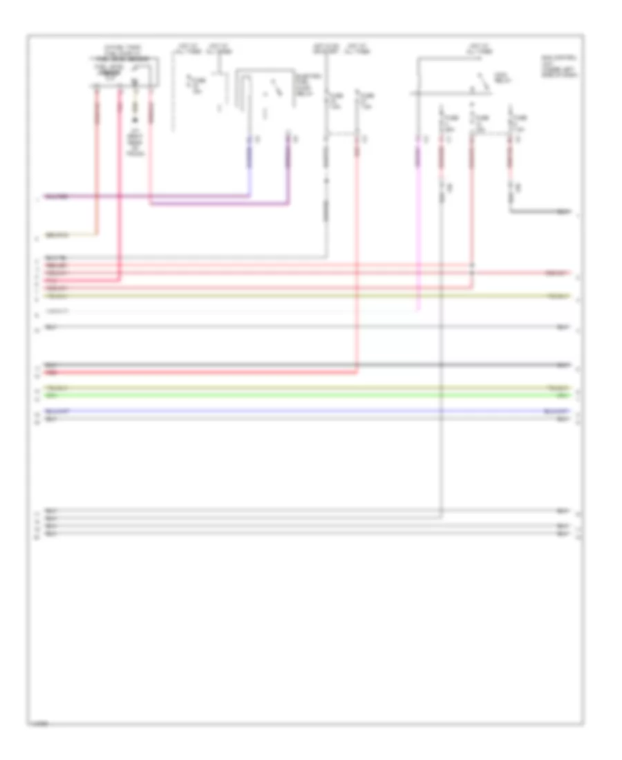
1.0L, Engine Performance Wiring Diagram (1 of 4) for Smart Fortwo Electric Drive 2013

List of elements for 1.0L, Engine Performance Wiring Diagram (1 of 4) for Smart Fortwo Electric Drive 2013:
- (center of dash) secondary air injection pump relay
- (on accelerator pedal assembly) accelerator pedal sensor
- (on engine assembly) secondary air injection pump
- (on fuel tank) fuel tank pressure sensor
- (pins 1-53 not used)
- 87/1.1
- Activated charcoal filter shut-off valve (left side of engine compt)
- Adjustable camshaft timing solenoid (top front of engine)
- Air pump
- Can h
- Can l
- Check engine mil ind
- Computer data lines system
- Cruise control system
- Cruise control system computer data lines system
- Ekpr
- Engine oil pressure switch (on oil filter housing)
- Euv
- Fuse 36 40a
- Gnd
- Hot at all times
- Instrument cluster
- Kwdg
- Lshhk
- M sensor
- Me-sfi (me) control unit (right rear of luggage compt)
- Nwdg
- Nws
- Pnk
- Pwg1
- Pwg2
- Red
- Secondary air injection pump fuse
- Secondary air injection pump switchover valve
- Tev
- Tp sig
- W11/5 (behind right rear bumper)
- W7 (right rear of trunk)
- X15
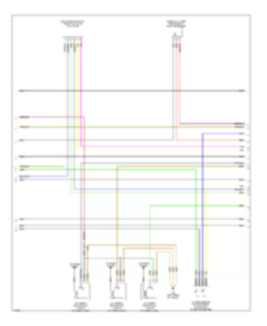
1.0L, Engine Performance Wiring Diagram (2 of 4) for Smart Fortwo Electric Drive 2013
List of elements for 1.0L, Engine Performance Wiring Diagram (2 of 4) for Smart Fortwo Electric Drive 2013:
- (in fuel tank) fuel pump w/ fuel level sensor
- Electric fuel pump relay
- Fuel level sensor
- Fuse 15a
- Fuse 25a
- Fuse 7.5a
- Hot at all times
- Hot in on or start
- Main relay
- Pnk
- Red
- Sam control unit (under left side of dash)
- W7 (right rear of trunk)
- X26
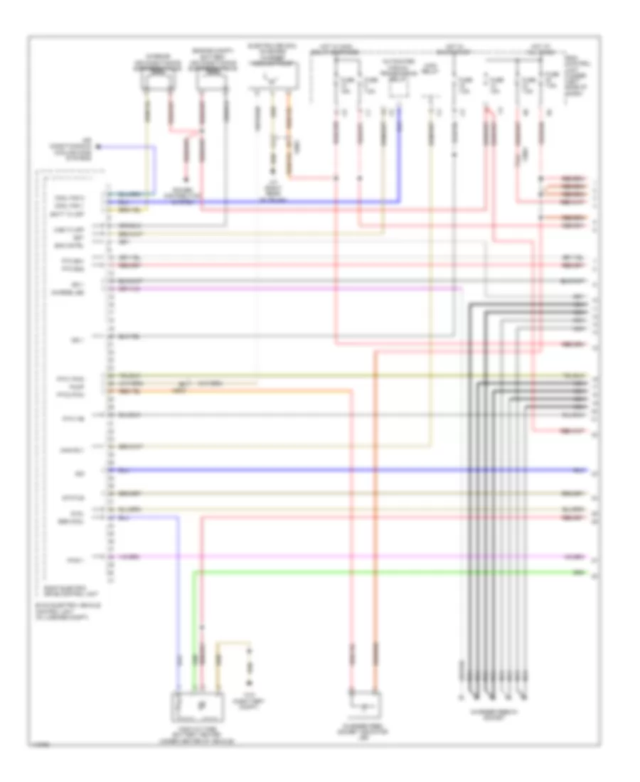
1.0L, Engine Performance Wiring Diagram (3 of 4) for Smart Fortwo Electric Drive 2013
List of elements for 1.0L, Engine Performance Wiring Diagram (3 of 4) for Smart Fortwo Electric Drive 2013:
- (near oil filter) crankshaft position sensor
- (on intake manifold) throttle valve actuator
- Cylinder 1 ignition coil (top of cylinder head)
- Cylinder 2 ignition coil (top of cylinder head)
- Cylinder 3 ignition coil (top of cylinder head)
- Nca
- Oxygen sensor (downstream) (in exhaust, after converter)
- Red
- Sig
- To spark plugs
- W6 (left rear of trunk)
- X26
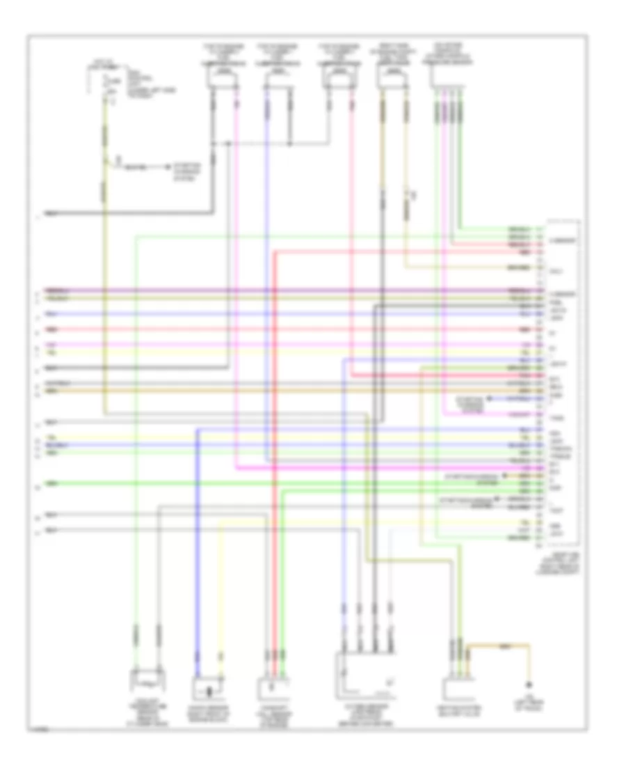
1.0L, Engine Performance Wiring Diagram (4 of 4) for Smart Fortwo Electric Drive 2013
List of elements for 1.0L, Engine Performance Wiring Diagram (4 of 4) for Smart Fortwo Electric Drive 2013:
- (on intake manifold) intake manifold pressure sensor
- (right side of engine compt) fuel tank vent valve
- (top of engine) cylinder 1 fuel injection valve
- (top of engine) cylinder 2 fuel injection valve
- (top of engine) cylinder 3 fuel injection valve
- Camshaft hall sensor (top rear of engine)
- Charging
- Coolant temperature sensor (rear of cylinder head)
- Ev1
- Ev2
- Ev3
- Fuse 25a
- Heating system shutoff valve
- Hot at all times
- Knock sensor (right front of engine block)
- Ksa
- Ksb
- Lshk
- Lshm
- Lshvk
- Lsuvm
- Lsvk
- M sensor
- Me-sfi (me) control unit (right rear of luggage compt)
- Nca
- Oalv
- Oxygen sensor (upstream) (in exhaust, before converter)
- Pnk
- Poel
- Red
- Sam control unit (under left side of dash)
- Sig
- Starting/
- Starting/ charging system
- Starting/charging system
- System
- Tans
- Tmot
- Tpsmain
- Tpssub
- W6 (left rear of trunk)
- X26
- Zeu3
- Zue1
- Zue2
ELECTRIC
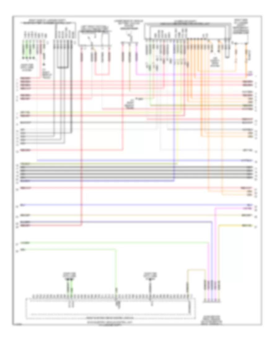
Electric, Engine Performance Wiring Diagram (1 of 4) for Smart Fortwo Electric Drive 2013
List of elements for Electric, Engine Performance Wiring Diagram (1 of 4) for Smart Fortwo Electric Drive 2013:
- (engine compt) battery air conditioning expansion valve
- 5vol
- Air conditioning & cooling fans systems
- Automated manual transmission relay
- Batt tx off
- Cab tx off
- Charge led
- Charger feed socket indicator led
- Charger feed-in socket
- Cool fan 1
- Cool fan 2
- Eac cntrl
- Electric drive & on board charger coolant pump
- Ess cool
- Evcm electric vehicle control unit (in luggage compt)
- Fuse 10a
- Fuse 15a
- Fuse 7.5a
- Gst
- High-voltage battery heater (under center of vehicle)
- Hot at all times
- Hot in on or start
- Hot w/ main relay energized
- Ign 1
- Interior air conditioning expansion valve
- Main relay
- Main rly
- Nca
- Power distribution system
- Ptc en1
- Ptc en2
- Ptc1 fb
- Ptc1 pwm
- Ptc3 pwm
- Pump
- Pwg 1
- Right electric drive control unit
- Sam control unit (under left side of dash)
- Sig
- Status
- W10 (in battery compt)
- W7 (right rear of trunk)
- X99/3
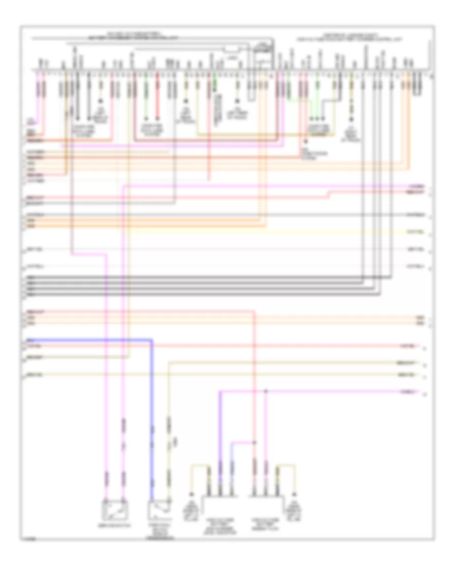
Electric, Engine Performance Wiring Diagram (2 of 4) for Smart Fortwo Electric Drive 2013
List of elements for Electric, Engine Performance Wiring Diagram (2 of 4) for Smart Fortwo Electric Drive 2013:
- (in service compt) high-voltage distributor control unit
- (left front footwell) high-voltage battery heater booster relay
- (right rear of trunk)
- (right side of luggage compt) refrigerant compressor control unit
- (right side of luggage compt) smart battery charger control unit
- (under rear of vehicle) battery cooling system coolant pump
- +12v
- +ve
- -ve
- Accelerator pedal sensor (on accelerator pedal assembly)
- Air conditi- oning system
- Can h
- Can l
- Computer data lines system
- Eaceb
- Eacen
- Evcm electric vehicle control unit (in luggage compt)
- Gnd
- H2v
- Hvl-ip
- Hvl-op
- Ign 5
- Ign3
- M gnd
- M live
- M neuatral
- M sensor
- N116/1x2
- Nca
- Pcrx
- Pctx
- Pcv
- Pilot sig
- Pos2
- Ptc bb1
- Ptc en1
- Ptc en2
- Pwm
- Right electric drive control module
- Therm gnd
- W7 (right rear of trunk)
- X99/3
- X99/4
Electric, Engine Performance Wiring Diagram (3 of 4) for Smart Fortwo Electric Drive 2013
List of elements for Electric, Engine Performance Wiring Diagram (3 of 4) for Smart Fortwo Electric Drive 2013:
- (center of luggage compt) high-voltage ac/dc battery charger control unit
- (on high voltage battery) battery management system control unit
- +12v
- +300v
- -300v
- Air conditioning system
- Bat can h
- Bat can l
- Computer data lines system
- Cont no
- Emerg line
- Gnd
- Heater
- High voltage battery
- High-voltage battery energy flow
- High-voltage battery sos charger level indicator
- Hvil in
- Hvl out
- Ign2
- Ign4
- Lines system computer data
- Logic
- M gnd
- M live
- M neuatral
- Mvp
- Nca
- Nca nca nca nca
- Park pawl switch (side of transmission)
- Pilot sig
- Pump
- Pwm pump
- Red
- Service switch
- Shield
- Sig gnd
- W6 (left rear of trunk)
- W7 (right rear of trunk)
- W9 (near base of left "a" pillar)
- X99/3
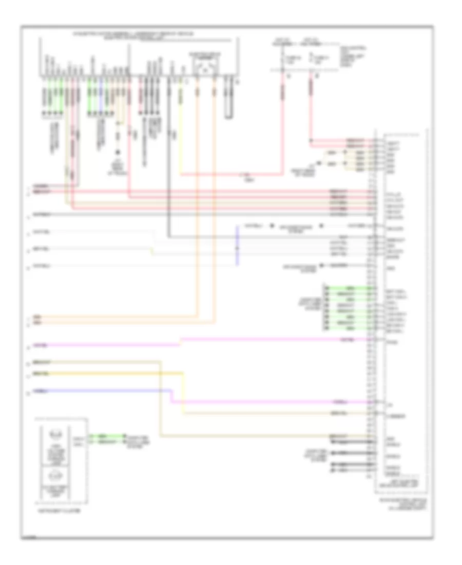
Electric, Engine Performance Wiring Diagram (4 of 4) for Smart Fortwo Electric Drive 2013
List of elements for Electric, Engine Performance Wiring Diagram (4 of 4) for Smart Fortwo Electric Drive 2013:
- (in electric motor assembly, under right rear of vehicle) electric motor control unit
- +12v
- 12v battery warning lamp
- Air conditioning system
- Bat can h
- Bat can l
- Boot wd
- Can h
- Can l
- Computer data lines system
- Eacfb
- Ed can h
- Ed can l
- Electric drive motor
- Evcm electric vehicle control unit (in luggage compt)
- Fuse 41 15a
- Fuse 42 7.5a
- Gddl 1
- Gddl 3
- Gden out
- Gnd
- High- voltage system warning lamp
- Hot at all times
- Hvil out
- Hvil_in
- Ign 1
- Ign out
- Ign out2
- Ign out3
- Ign out5
- Ign out6
- Ign3
- Ign4
- Instrument cluster
- Left electric drive control unit
- Lin
- Log can h
- Log can l
- M sensor
- Nca
- Pwg2
- Sam control unit (under left side of dash)
- Sel 1
- Sel 2
- Shield
- System data lines computer
- Vbatt
- W7 (right rear of trunk)
- X99/3
- X99/4