ENGINE PERFORMANCE
2.2L
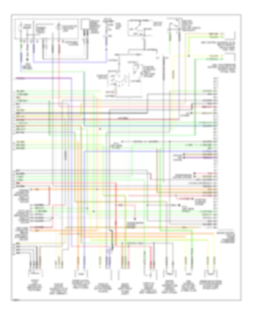
2.2L, Engine Performance Wiring Diagrams (1 of 2) for Subaru Impreza RS 1998

List of elements for 2.2L, Engine Performance Wiring Diagrams (1 of 2) for Subaru Impreza RS 1998:
- (behind left side of dash) fuel pump relay
- (behind left side of dash) main relay
- (below rear of vehicle, in fuel tank) fuel pump & fuel gauge module
- (brhind left side of dash, taped to harn) check connector
- (on right side of trunk)
- A/c system
- B152
- B158
- Camshaft position sensor (on left of eng)
- Crankshaft position sensor (on lower front of eng)
- Engine control module (under passenger floorboard)
- F37
- Fuel gauge
- Fuel gauge sub module (awd) (below rear of vehicle, near fuel tank)
- Fuel injectors
- Fuel temp gauge
- Fuse & relay box
- Fuse 10a
- Fuse 15a
- G103 (right front shock tower)
- G107 (behind right headlamp)
- G114 (left rear of eng)
- G407 (center rear of trunk)
- Hot at all times
- Hot in run or start
- Ignition coil (on top front of eng)
- Ignitor (on center of firewall)
- Knock sensor (on left side of eng)
- Main fuse box
- Nca
- Oxygen sensor (front) (on front of front catalytic converter)
- Oxygen sensor (rear) (on rear of rear catalytic converter)
- Red
- Sbf-5 30a
- Trans- missions control system
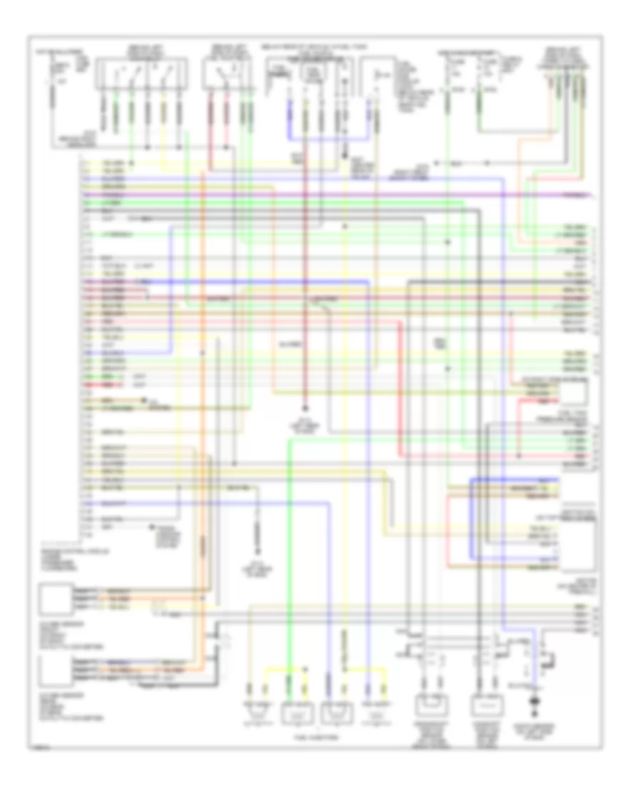
2.2L, Engine Performance Wiring Diagrams (2 of 2) for Subaru Impreza RS 1998
List of elements for 2.2L, Engine Performance Wiring Diagrams (2 of 2) for Subaru Impreza RS 1998:
- (m/t)
- (on air cleaner housing)
- (right front of eng compt)
- A/c system
- A/t
- Acc
- Boost sensor
- Cooling fan system
- Data link connector (behind dash, right of
- Dignosis connector (behind dash, right of steering column)
- Egr solenoid (on top left side of eng, at egr valve)
- Engine control module (under passenger floorboard)
- Engine coolant temperature sensor (top right front of eng)
- F68
- Fuel tank pressure control solenoid valve (on right front of fuel tank)
- Fuse 15a
- G114 (left rear of eng)
- G202 (center of dash)
- Hot at all times
- I10
- I12
- Idle air control solenoid valve (on throttle body assembly)
- Ignition switch
- Inhibitor switch
- Instrument cluster
- M/t
- Main fuse box
- Malfunction indicator lamp
- Mass air flow sensor
- Nca
- Neutral position switch (on left side of eng compt)
- Off
- Pnk
- Pressure sources switching solenoid (on right side of eng compt)
- Purge control solenoid valve (on top right front of eng)
- Red
- Shield joint connector (behind right kick panel)
- Speedo- meter circuit
- Start
- Starter interlock relay (left side of dash)
- Starting/ charging system
- Steering column)
- Tacho- meter
- Test mode connector (behind dash, right of steering column)
- Throttle position sensor (on throttle body assembly)
- Transmissions control system
- Vehicle speed sensor 2 (side of trans- mission)
- Vent control solenoid valve (below rear of vehicle, near fuel tank)
2.5L
2.5L, Engine Performance Wiring Diagrams (1 of 2) for Subaru Impreza RS 1998
List of elements for 2.5L, Engine Performance Wiring Diagrams (1 of 2) for Subaru Impreza RS 1998:
- (behind left side of dash) fuel pump relay
- (behind left side of dash) main relay
- (below rear of vehicle, in fuel tank) fuel pump & fuel gauge module
- (brhind left side of dash, taped to harn) check connector
- (on right side of trunk)
- A/c system
- B152
- B158
- Camshaft position sensor (on left of eng)
- Crankshaft position sensor (on lower front of eng)
- Engine control module (under passenger floorboard)
- F37
- Fuel gauge
- Fuel gauge sub module (awd) (below rear of vehicle, near fuel tank)
- Fuel injectors
- Fuel temp gauge
- Fuse & relay box
- Fuse 10a
- Fuse 15a
- G103 (right front shock tower)
- G107 (behind right headlamp)
- G114 (left rear of eng)
- G407 (center rear of trunk)
- Hot at all times
- Hot in run or start
- Ignition coil (on top front of eng)
- Ignitor (on center of firewall)
- Knock sensor (on left side of eng)
- Main fuse box
- Nca
- Oxygen sensor (front) (on front of front catalytic converter)
- Oxygen sensor (rear) (on rear of rear catalytic converter)
- Red
- Sbf-5 30a
- Trans- missions control system
2.5L, Engine Performance Wiring Diagrams (2 of 2) for Subaru Impreza RS 1998
List of elements for 2.5L, Engine Performance Wiring Diagrams (2 of 2) for Subaru Impreza RS 1998:
- (m/t)
- (on air cleaner housing)
- (right front of eng compt)
- A/c system
- A/t
- Acc
- Boost sensor
- Cooling fan system
- Data link connector (behind dash, right of
- Dignosis connector (behind dash, right of steering column)
- Egr solenoid (on top left side of eng, at egr valve)
- Engine control module (under passenger floorboard)
- Engine coolant temperature sensor (top right front of eng)
- F68
- Fuel tank pressure control solenoid valve (on right front of fuel tank)
- Fuse 15a
- G114 (left rear of eng)
- G202 (center of dash)
- Hot at all times
- I10
- I12
- Idle air control solenoid valve (on throttle body assembly)
- Ignition switch
- Inhibitor switch
- Instrument cluster
- M/t
- Main fuse box
- Malfunction indicator lamp
- Mass air flow sensor
- Nca
- Neutral position switch (on left side of eng compt)
- Off
- Pnk
- Pressure sources switching solenoid (on right side of eng compt)
- Purge control solenoid valve (on top right front of eng)
- Red
- Shield joint connector (behind right kick panel)
- Speedo- meter circuit
- Start
- Starter interlock relay (left side of dash)
- Starting/ charging system
- Steering column)
- Tacho- meter
- Test mode connector (behind dash, right of steering column)
- Throttle position sensor (on throttle body assembly)
- Transmissions control system
- Vehicle speed sensor 2 (side of trans- mission)
- Vent control solenoid valve (below rear of vehicle, near fuel tank)