ENGINE PERFORMANCE
2.0L
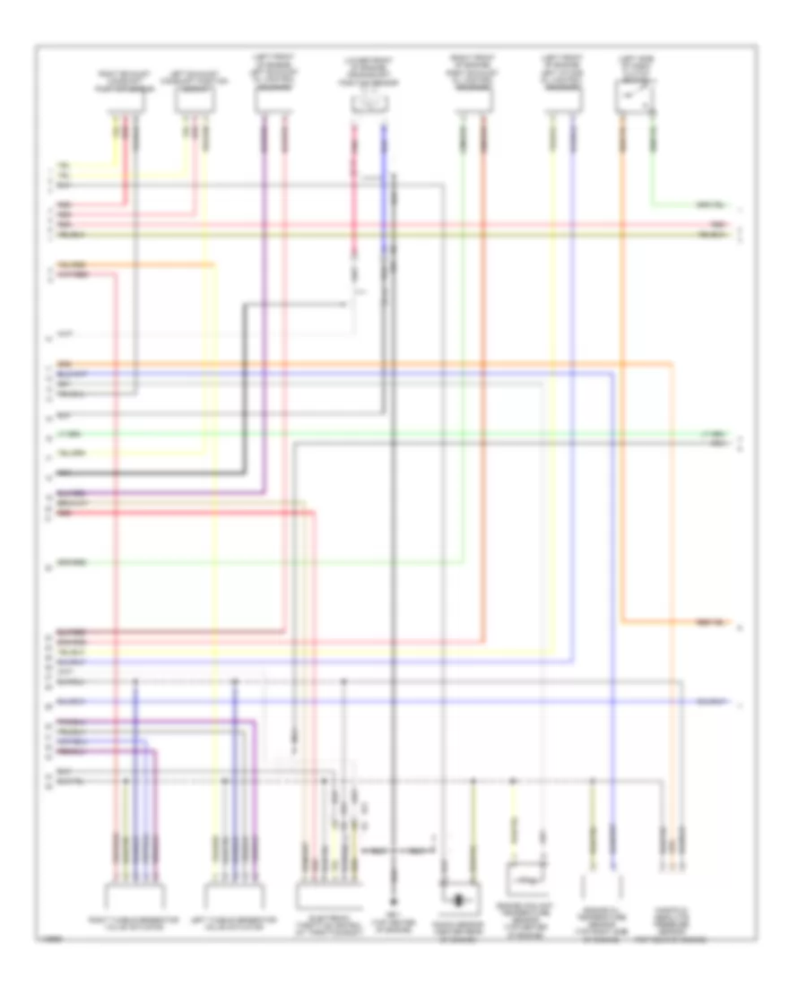
2.0L, Engine Performance Wiring Diagram (1 of 5) for Subaru Impreza Sport Limited 2014

List of elements for 2.0L, Engine Performance Wiring Diagram (1 of 5) for Subaru Impreza Sport Limited 2014:
- (ho-turbo: left rear of engine) left intake camshaft position sensor
- (left front of engine) fuel injector 2
- (left rear of engine) fuel injector 4
- (on intake manifold) purge control solenoid valve
- (right front of engine) fuel injector 1
- (right rear of engine) fuel injector 3
- (right rear of engine) right intake camshaft position sensor
- (top right side of engine)
- B134
- B137
- B21
- B21 e2
- Egr control valve (rear of engine)
- Engine control module (right side of dash)
- Ge-1 (top center of engine)
- Ge-2 (top center of engine)
- Ignition coil 1
- Ignition coil 2
- Ignition coil 3
- Ignition coil 4
- Nca
- Pnk
- Red
- Right intake oil control solenoid (right front of engine)
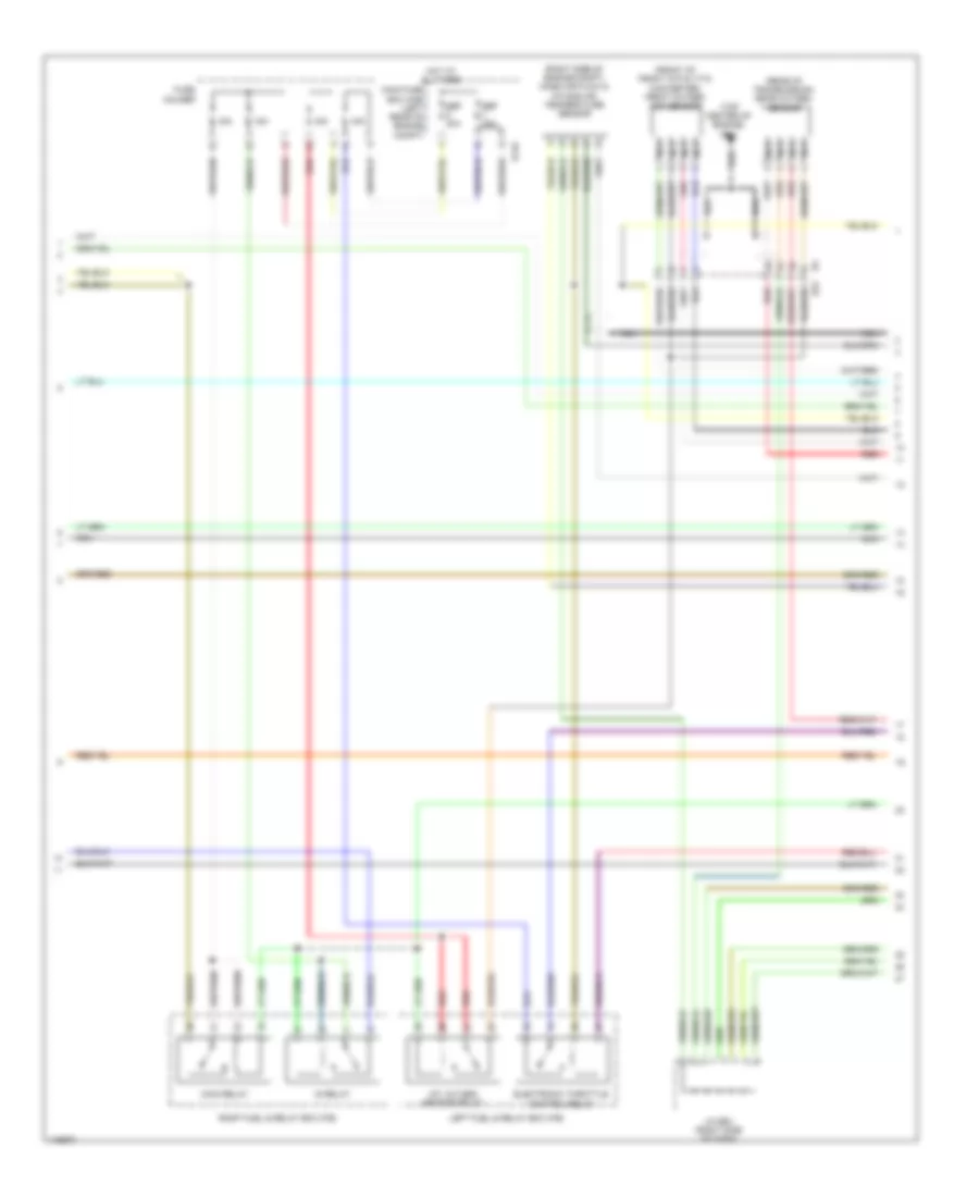
2.0L, Engine Performance Wiring Diagram (2 of 5) for Subaru Impreza Sport Limited 2014
List of elements for 2.0L, Engine Performance Wiring Diagram (2 of 5) for Subaru Impreza Sport Limited 2014:
- (left front of engine) left exhaust oil control solenoid
- (left front of engine) left intake oil control solenoid
- (left side of dash) clutch switch
- (lower front of engine) crankshaft position sensor
- (right front of engine) right exhaust oil control solenoid
- B21 e2
- E2 b21
- Electronic throttle control (at throttle body)
- Engine coolant temperature sensor (top center of engine)
- Engine oil temperature sensor (top right side of engine)
- Ge-1 (top center of engine)
- Knock sensor (center rear of engine)
- Left exhaust camshaft position sensor
- Left tumble generator valve actuator
- Manifold absolute pressure sensor (top rear of engine)
- Nca
- Pnk
- Red
- Right exhaust camshaft position sensor
- Right tumble generator valve actuator
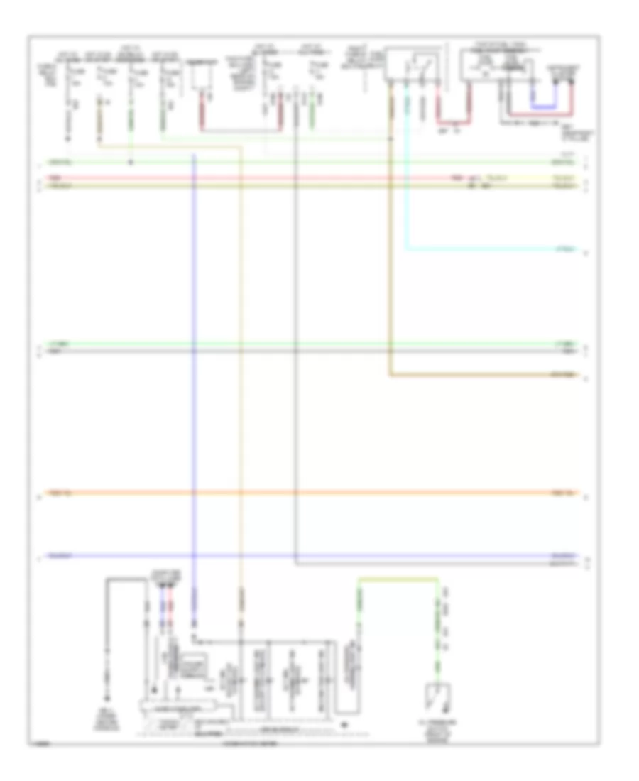
2.0L, Engine Performance Wiring Diagram (3 of 5) for Subaru Impreza Sport Limited 2014
List of elements for 2.0L, Engine Performance Wiring Diagram (3 of 5) for Subaru Impreza Sport Limited 2014:
- (co model)
- (except for co model) ect warning light ind
- (top of fuel tank) fuel pump assembly
- B143
- B186
- B21
- B52
- B553
- B97
- Co model) (except for
- Combination meter
- Computer data lines system
- Drive circuit
- Eco gauge (if
- Ect ind
- Ect warning light ind ect ind/
- Equipped)
- F26
- F37
- Fuel level sensor
- Fuel pump
- Fuel pump relay
- Fuse & relay box (f/b)
- Fuse 10a
- Fuse 15a
- Fuse 7.5a
- Gb-11 (under center console)
- Gb-7 (near right "c" pillar)
- Generator
- Hot at all times
- Hot in on or start
- Hot w/ ig2 relay energized
- I/f
- I231
- Instrument cluster system
- Main fuse box (m/b) (left rear of engine compt)
- Malfunction light ind
- Micro computer
- Nca
- Oil pressure switch (front of engine)
- Receiver transceiver & can
- Red
- Right fuse & relay box (f/b)
- Tacho- meter
- Warning light ind oil pressure
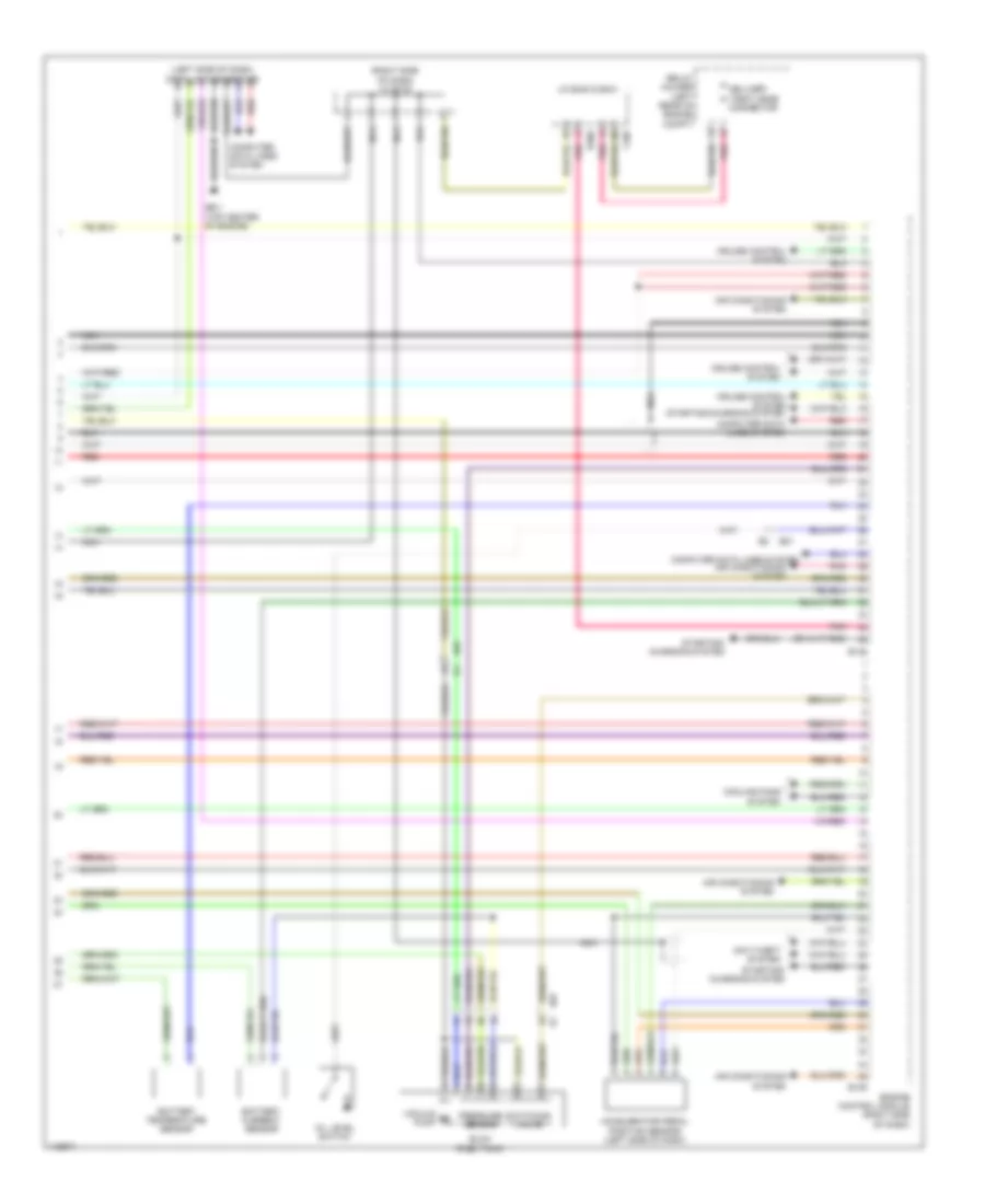
2.0L, Engine Performance Wiring Diagram (4 of 5) for Subaru Impreza Sport Limited 2014
List of elements for 2.0L, Engine Performance Wiring Diagram (4 of 5) for Subaru Impreza Sport Limited 2014:
- (front of front catalytic converter) front oxygen (a/f) sensor
- (rear of transmission) rear oxygen sensor
- (right side of engine compt) mass air flow & intake air temperature sensor
- (top center of engine) ge-1
- 15a
- A/f, oxygen sensor relay
- B145
- B22
- Electronic throttle control relay
- Fuse holder
- Hot at all times
- Ig relay
- J/c b83 (right side of dash)
- Left fuel & relay box (f/b)
- Main fuse box (m/b) (left rear of engine compt)
- Main relay
- Nca
- Pnk
- Red
- Right fuel & relay box (f/b)
- Sbf 30a
2.0L, Engine Performance Wiring Diagram (5 of 5) for Subaru Impreza Sport Limited 2014
List of elements for 2.0L, Engine Performance Wiring Diagram (5 of 5) for Subaru Impreza Sport Limited 2014:
- (left side of dash) data link connector
- (right side of dash) j/c b122
- Accelerator pedal position sensor (left side of dash)
- Air conditioning system
- Anti-theft system
- B135
- B136
- B21
- B360
- B97
- Battery current sensor
- Battery temperature sensor
- Computer data lines system
- Cooling fans system
- Cruise control system
- Cruise control system starting/charging system
- Delivery (test) mode connector
- Elcm (fuel tank)
- Engine control module (right side of dash)
- F109
- Ge-1 (top center of engine)
- J/c b440 & b441
- Nca
- Oil level switch
- Pnk
- Pressure sensor
- Pump
- Red
- Relay holder (left rear of engine compt)
- Starting/ charging system
- Switching valve
- Vacuum m