ENGINE PERFORMANCE
2.2L
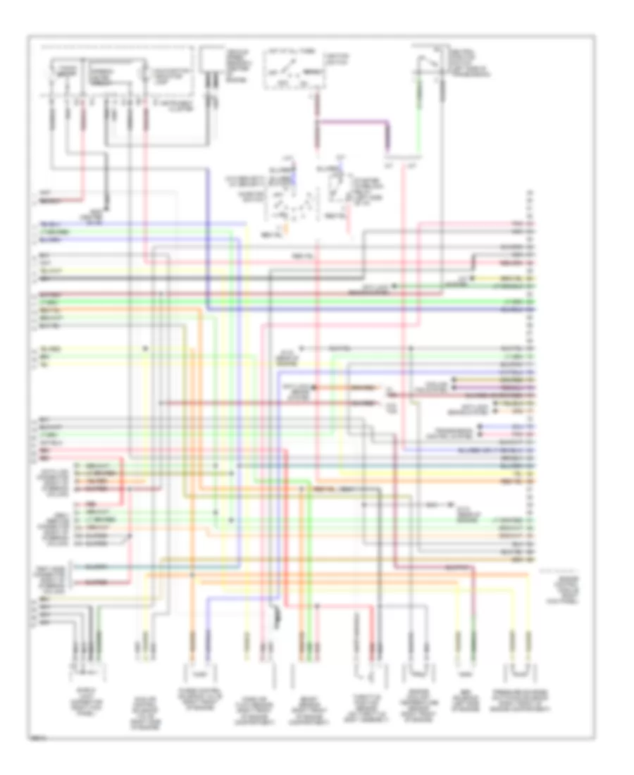
2.2L, Engine Performance Wiring Diagrams (1 of 2) for Subaru Legacy Outback 1997

List of elements for 2.2L, Engine Performance Wiring Diagrams (1 of 2) for Subaru Legacy Outback 1997:
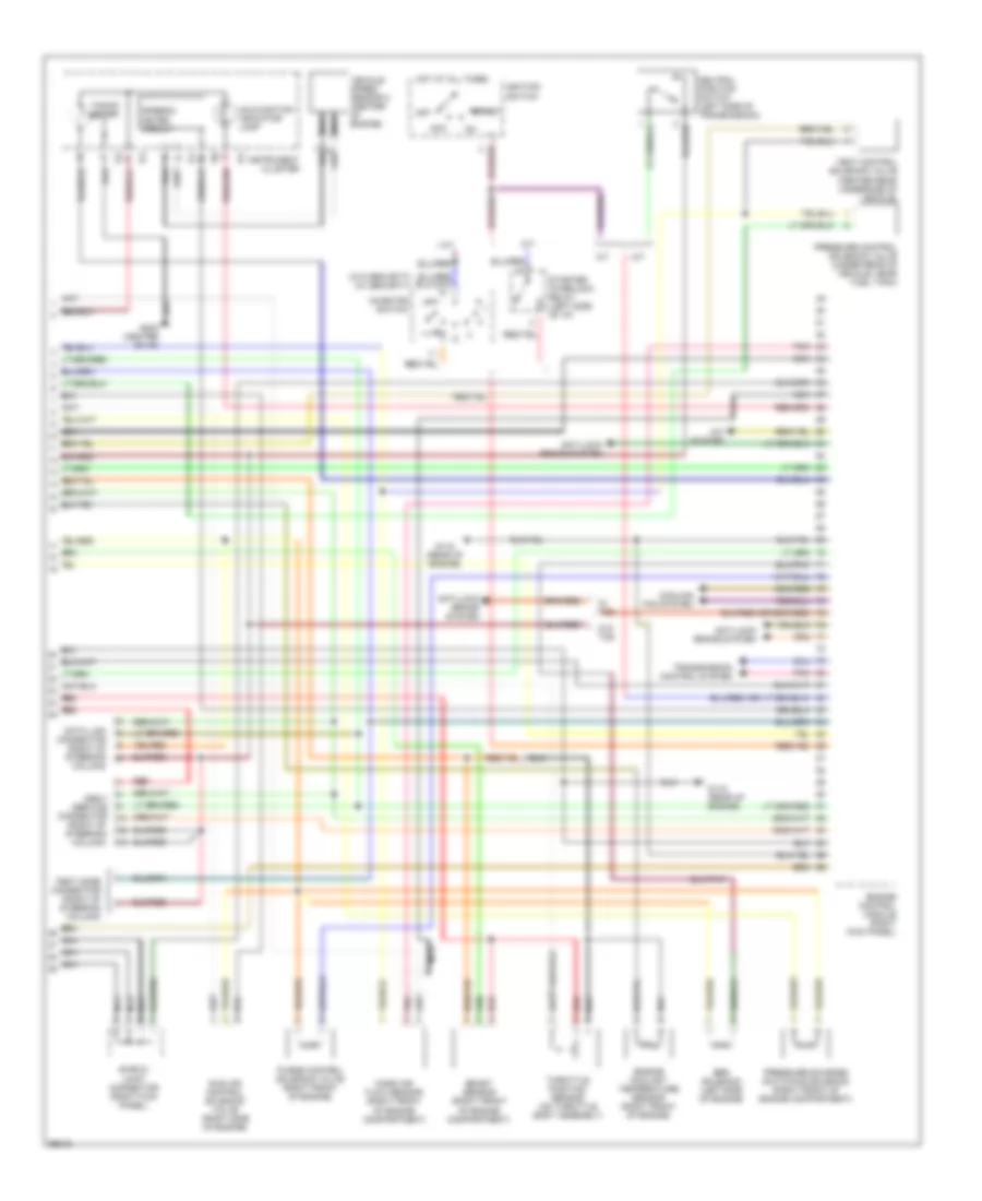
2.2L, Engine Performance Wiring Diagrams (2 of 2) for Subaru Legacy Outback 1997
List of elements for 2.2L, Engine Performance Wiring Diagrams (2 of 2) for Subaru Legacy Outback 1997:
2.5L
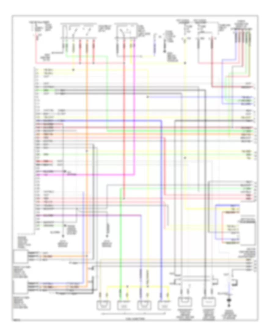
2.5L, Engine Performance Wiring Diagrams (1 of 2) for Subaru Legacy Outback 1997
List of elements for 2.5L, Engine Performance Wiring Diagrams (1 of 2) for Subaru Legacy Outback 1997:
2.5L, Engine Performance Wiring Diagrams (2 of 2) for Subaru Legacy Outback 1997
List of elements for 2.5L, Engine Performance Wiring Diagrams (2 of 2) for Subaru Legacy Outback 1997: