ENGINE PERFORMANCE
1.3L
1.3L TBI, Engine Performance Wiring Diagrams (1 of 2) for Suzuki Samurai JL 1992

List of elements for 1.3L TBI, Engine Performance Wiring Diagrams (1 of 2) for Suzuki Samurai JL 1992:
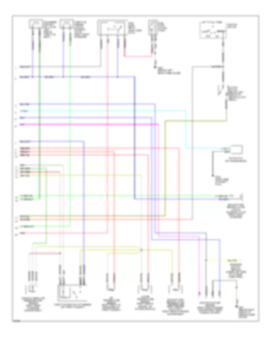
1.3L TBI, Engine Performance Wiring Diagrams (2 of 2) for Suzuki Samurai JL 1992
List of elements for 1.3L TBI, Engine Performance Wiring Diagrams (2 of 2) for Suzuki Samurai JL 1992: