ENGINE PERFORMANCE
1.6L
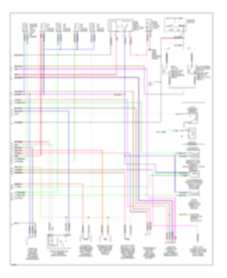
1.6L PFI, Engine Performance Wiring Diagrams (1 of 2) for Suzuki Sidekick JLX 1995

List of elements for 1.6L PFI, Engine Performance Wiring Diagrams (1 of 2) for Suzuki Sidekick JLX 1995:
- (canada built)
- (japan built)
- (left side of engine, in exhaust manifold)
- (rear of
- 3 a/t only
- 4 a/t only
- A/c amplifier
- A/t controller
- A/t tcc relay (3 a/t only) (right side of engine compt)
- A10
- A11
- A12
- A13
- A14
- A15
- A16
- A17
- A18
- A19
- A20
- A21
- A22
- B10
- B11
- B12
- B13
- B14
- B15
- B16
- B17
- B18
- B19
- B20
- B21
- B22
- B23
- B24
- B25
- B26
- Brake light switch (a/t only) (under left side of i/p, above brake pedal)
- California
- Camshaft position sensor
- Cas
- Check eng lt
- Diag terminal
- Distributor
- Duty output
- E33
- E34
- Ects
- Egr vsv
- Egrt
- Engine control module (ecm) (left side of i/p)
- Engine)
- Evap sp valve
- Fuel level
- Fuel level gauge (in fuel tank)
- Fuel pump relay
- Fuse 13 15a
- Fuse 18 15a
- Fuse 24 15a
- Fuse box (left side of i/p)
- G115
- G115 (rear of engine)
- G121 (center of safety wall)
- G904 (left rear quarter panel)
- Ground
- Heated oxygen sensor (ho2s)
- Ho2s
- Hot at all times
- Hot in start or on
- Iat sensor
- Idle air cntrl valve
- Idle sw
- Igniter
- Igniter (rear of engine compt)
- Ignition coil
- Ignition coil (left rear of engine compt)
- Inj #1
- Inj #2
- Inj #3
- Inj #4
- Instrument panel cluster assembly
- Mafs
- Main relay
- Main relay (left side of i/p)
- Malfunction indicator lamp
- Nca
- Noise filter (left rear of engine compt)
- O2 sensor heater
- Only
- P/s pres sw
- Pnk
- Power
- Power steering pressure switch (in power steering pump)
- Pressure ctrl sol
- Red
- Sensor ground
- Serial data
- Shift sw
- Start sw
- Test sw terminal
- Tps
- Vss
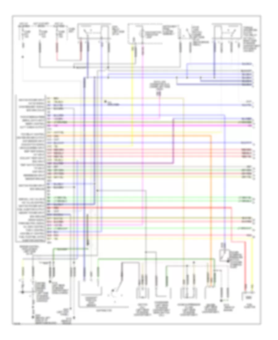
1.6L PFI, Engine Performance Wiring Diagrams (2 of 2) for Suzuki Sidekick JLX 1995
List of elements for 1.6L PFI, Engine Performance Wiring Diagrams (2 of 2) for Suzuki Sidekick JLX 1995:
- (behind left side of i/p, above brake pedal)
- (behind left side of i/p, above clutch pedal)
- (engine) (right rear of engine compt)
- A/t
- A/t only
- Acc
- Automatic
- Clutch pedal position (cpp) switch
- Data link connector (dlc) (under left side of i/p, near fuse panel)
- Engine coolant temperature (ect) sensor (front of engine)
- Evap solenoid purge valve (front of engine)
- Exhaust gas
- Exhaust gas recirculation solenoid vacuum (egr sv) valve (front of engine)
- Fluid pressure switch
- Fuel pump (in fuel tank)
- Fuel pump relay (left side of i/p)
- G904 (left rear quarter panel)
- Hot at all times
- Idle air control (iac) valve (top of engine)
- Ignition switch
- Inj #1 (top of engine)
- Inj #2 (top of engine)
- Inj #3 (top of engine)
- Inj #4 (top of engine)
- Intake air temperature (iat) sensor (right front of engine compartment)
- Lock
- Lock up solenoid
- M/t
- Mass air flow (maf) sensor (left front of engine compartment)
- Monitor connector
- Monitor connector (engine, rwal & a/t)
- Not used
- Pnk
- Recirculation temperature (egrt) sensor (right rear of engine compartment)
- Red
- Shift switch
- Start
- Tank pressure control solenoid vacuum valve (right side of engine)
- Throttle position (tp) sensor (rear of engine)
- Transmission
- Transmission control module (right side of steering column)
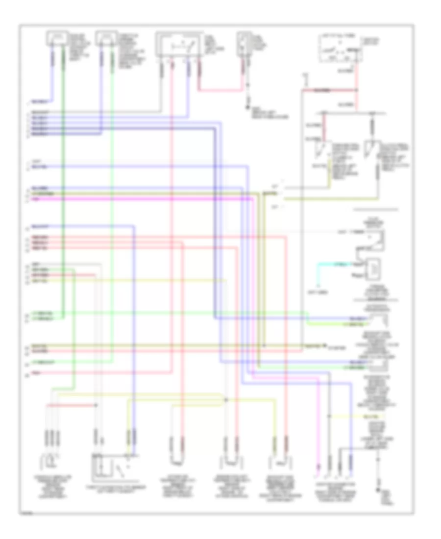
1.6L TBI, Engine Performance Wiring Diagrams (1 of 2) for Suzuki Sidekick JLX 1995
List of elements for 1.6L TBI, Engine Performance Wiring Diagrams (1 of 2) for Suzuki Sidekick JLX 1995:
- (a/t only) (right side of engine compartment on fusible link box)
- (rear of
- A/c amplifier
- A/c on signal
- A10
- A11
- A12
- A13
- A14
- A15
- A16
- A17
- A18
- A19
- A20
- A21
- A22
- A23
- A24
- B10
- B11
- B12
- B13
- B14
- B15
- B16
- B17
- Camshaft position (cmp) sensor
- Cmp sensor input
- Condenser (left rear of engine compartment near ignition coil)
- Coolant temp input
- Crank signal
- Data link connector (dlc) (under left side of i/p)
- Diag request signal
- Distributor
- Duty check output
- E33
- E34
- Ecm gnd (calif)
- Ecm ground
- Eespv control
- Egr sol vac valve in
- Egr temp signal
- Engine control module (ecm) (left side of i/p)
- Engine)
- Eoc input
- Fuel injector
- Fuel injector output
- Fuel pump rel cntrl
- Fuse #13 15a
- Fuse #18 15a
- Fuse #24 15a
- Fuse box
- G115
- G115 (rear of engine)
- G116 (left rear of engine compartment on bulkhead)
- G200 (behind left side of i/p near fuse block)
- G200 (left kick panel)
- Heated oxygen sensor (ho2s) (left side of engine in exhaust manifold)
- Hot at all times
- Hot in start or on
- Iac valve control
- Iat input
- Idle switch signal
- Igniter (left rear of engine compartment)
- Igniter driver output
- Ignition coil (left rear of engine compartment)
- Ignition power input
- Injector control
- Instrument panel cluster assembly
- Main relay (left side of i/p)
- Main relay control
- Malfunction indicator lamp
- Map input
- Memory power input
- Mil indic control
- Nca
- Noise suppressor filter (left rear of engine compartment)
- Park/neutral signal
- Pnk
- Power steering pressure switch (in power steering pump)
- Pwr steering pres
- Red
- Reference input
- Sensor ground
- Serial data input
- Stop lamp switch (under left side of i/p, above brake pedal)
- Tcc relay control
- Test switch signal
- Torque converter clutch (tcc) relay
- Tosvv control
- Tp input
- Vehicle speed input
- Vss
1.6L TBI, Engine Performance Wiring Diagrams (2 of 2) for Suzuki Sidekick JLX 1995
List of elements for 1.6L TBI, Engine Performance Wiring Diagrams (2 of 2) for Suzuki Sidekick JLX 1995:
- (behind left rear wheelhouse)
- (closed in p or n) (behind left side of i/p, above brake pedal)
- (not used)
- A/t
- Acc
- Automatic transmission
- Clutch pedal position (cpp) switch (behind left side of i/p, above clutch pedal)
- Engine coolant temperature (ect) sensor (right side of engine, on intake manifold)
- Evaporative emission solenoid purge valve (right side of engine compartment below thermostat housing)
- Exhaust gas recirculation solenoid vacuum (egr sv) valve (in engine compartment near valve cover)
- Exhaust gas recirculation temperature (egrt) sensor (calif only) (right rear of engine compartment)
- Fluid pressure switch
- Fuel pump (in fuel tank)
- Fuel pump relay (left side of i/p)
- G200 (left kick panel)
- G402
- Hot at all times
- Idle air control (iac) valve (on right side of throttle body)
- Ignition switch
- Intake air temperature (iat) sensor (right front of engine below throttle body)
- Lock
- M/t
- Manifold absolute pressure (map) sensor (right rear of engine compartment)
- Monitor connector (engine) (right side of engine compartment near fusible link box)
- Monitor coupler (engine/ rwal) (under left side of i/p, near fuse panel)
- Nca
- Park/neutral position (pnp) switch
- Pnk
- Start
- Starter
- Throttle opener solenoid vacuum (to sv) valve (in engine compartment, near valve cover)
- Throttle position (tp) sensor (on throttle body)
- Torque converter clutch (tcc) solenoid