ENGINE PERFORMANCE
3.6L
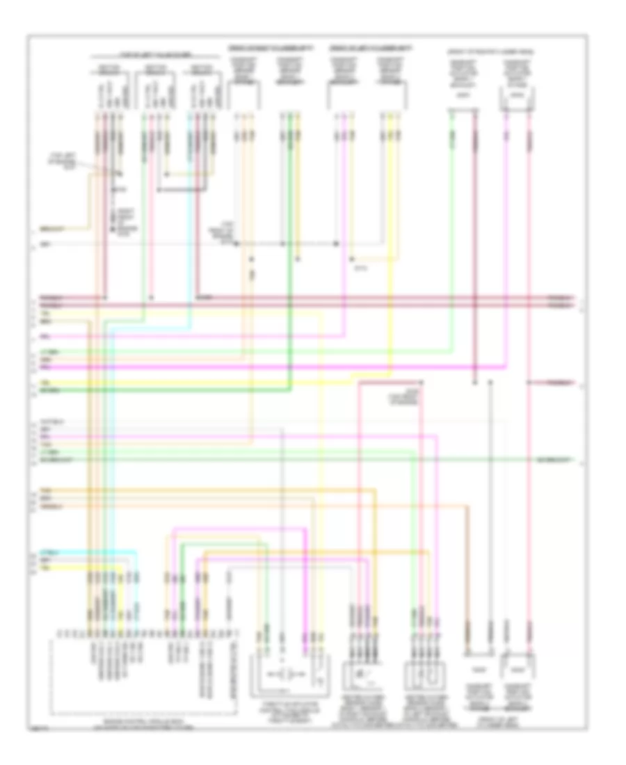
3.6L, Engine Performance Wiring Diagram (1 of 4) for Suzuki XL7 Luxury 2007

List of elements for 3.6L, Engine Performance Wiring Diagram (1 of 4) for Suzuki XL7 Luxury 2007:
- (front of right valve cover) s115
- (on top left side of engine, under intake plenum)
- (on top right side of engine, under intake plenum)
- (rear of left cylinder head) g107
- (top of right valve cover)
- 5 volt ref 2
- 5 volt ref 3
- Ckp sens 1 sig
- Cmp actuator exhaust 1
- Cmp actuator exhaust 2
- Cmp actuator intake 1
- Cmp actuator intake 2
- Cmp sens exhaust 1
- Cmp sens exhaust 2
- Cmp sens intake 1
- Cmp sens intake 2
- Crankshaft position (ckp) sensor (lower right rear of engine)
- Engine control module (ecm) (mounted on top of battery cover)
- Engine coolant temperature (ect) sensor (below brake master cylinder, rear of engine)
- Engine oil pressure (eop) switch (left side of engine, about starter motor)
- Evap canister purge
- Fuel inj 1 ctrl
- Fuel inj 2 ctrl
- Fuel inj 3 ctrl
- Fuel inj 4 ctrl
- Fuel inj 5 ctrl
- Fuel inj 6 ctrl
- Fuel injector
- Generator field duty sig
- Generator turn on sig
- Gnd
- Ho2s hi (bank 2 sens 1)
- Ho2s lo (bank 1 sens 1)
- Ho2s lo (bank 2 sens 1)
- Ic 1 ctrl
- Ic 3 ctrl
- Ic 5 ctrl
- Ign 1 volt
- Ignition coils 1
- Ignition coils 3
- Ignition coils 5
- Ignition ctrl 1
- Ignition ctrl 3
- Ignition ctrl 5
- Knock sensor (ks) 1 (lower rear of engine, near ckp sensor)
- Knock sensor (ks) 2 (on lower left side of engine)
- Ks 1 sig
- Ks 2 sig
- Low ref
- Oil pressure sw sig
- S101
- S104
- S106
- S114
- Starting/ charging system
- Tac mtr ctrl 1
- Tac mtr ctrl 2
- Tan
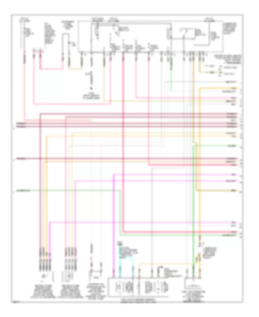
3.6L, Engine Performance Wiring Diagram (2 of 4) for Suzuki XL7 Luxury 2007
List of elements for 3.6L, Engine Performance Wiring Diagram (2 of 4) for Suzuki XL7 Luxury 2007:
- (front of left cylinder head)
- (front of right cylinder head)
- (right front of engine) g108
- (top front of engine) s110
- (top left of engine) s107
- (top of left valve cover)
- Camshaft position actuator (bank 1 exhaust)
- Camshaft position actuator (bank 1 intake)
- Camshaft position actuator (bank 2 exhaust)
- Camshaft position actuator (bank 2 intake)
- Camshaft position sensor (bank 1 exhaust)
- Camshaft position sensor (bank 1 intake)
- Camshaft position sensor (bank 2 exhaust)
- Camshaft position sensor (bank 2 intake)
- Ect sens sig
- Engine control module (ecm) (mounted on top of battery cover)
- Gnd
- Heated oxygen sensor (ho2s) bank 1 sensor 1 (in right exhaust manifold, before catalytic converter)
- Heated oxygen sensor (ho2s) bank 2 sensor 1 (in left exhaust manifold, before catalytic converter)
- Ho2s heater lo ctrl
- Ho2s hi (bank 1 sig 1)
- Ho2s lo (bank 2 sig 1)
- Ic 2 ctrl
- Ic 4 ctrl
- Ic 6 ctrl
- Ign 1 volt
- Ignition coil 2
- Ignition coil 4
- Ignition coil 6
- Ignition coils 2
- Ignition coils 4
- Ignition coils 6
- Ks 1 sig
- Ks 2 sig
- Low ref
- Nca
- S105
- S108
- S109 (top front of engine)
- S112
- Tan
- Throttle actuator control (tac) module (attached to throttle body)
- Tp sig 1
- Tp sig 2
3.6L, Engine Performance Wiring Diagram (3 of 4) for Suzuki XL7 Luxury 2007
List of elements for 3.6L, Engine Performance Wiring Diagram (3 of 4) for Suzuki XL7 Luxury 2007:
- (center of dash, behind hvac control module) body control module (bcm)
- (not used)
- Acc volt
- Can vent fuse 16 10a
- Evaporative emissions (evap) canister vent solenoid (on evap canister, in front of fuel tank)
- Fuel level sensor
- Fuel pump & sender assembly (inside right side of fuel tank)
- Fuel pump fuse 39 15a
- Fuel pump motor
- Fuel pump relay 62
- Fuel tank pressure (ftp) sensor (at top of primary fuel pump & sender assembly)
- G109 (right rear of cylinder head)
- G403 (under right side of luggage compt)
- Heated oxygen sensor (ho2s) bank 1 sensor 2 (in right exhaust down pipe, after catalytic converter)
- Heated oxygen sensor (ho2s) bank 2 sensor 2 (in left exhaust down pipe, after catalytic converter)
- Hot at all times
- Hot in run or start
- I/p fuse block (center of dash, beneath right side of radio)
- Ign main relay 32
- Instrument panel cluster (ipc)
- Maf fuse 24 10a
- Mil ind
- Nca
- Pcm ign fuse 22 10a
- Pnk
- S401
- Secondary
- Sensor fuel level primary
- Sir display fuse 25 10a
- Stop lp sw
- Tan
- Trans fuse 23 10a
- Underhood fuse block (left side of engine c2 compt)
- Underhood fuse block (left side of engine compt)
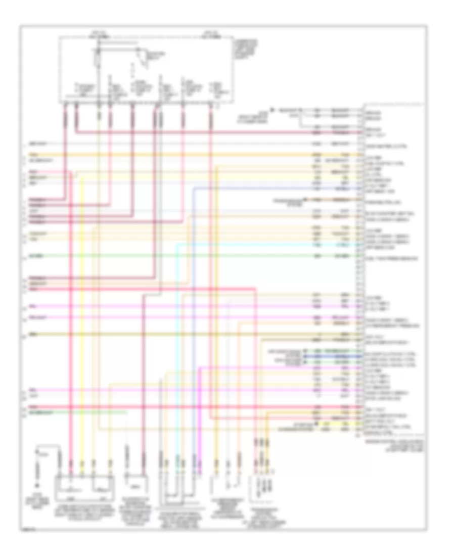
3.6L, Engine Performance Wiring Diagram (4 of 4) for Suzuki XL7 Luxury 2007
List of elements for 3.6L, Engine Performance Wiring Diagram (4 of 4) for Suzuki XL7 Luxury 2007:
- 5 volt ref 1
- 5 volt ref 2
- 5 volt ref 3
- A/c comp clutch rly ctrl
- A/c refrigerant press sig
- A/c refrigerant pressure sensor (near back of a/c compressor)
- Acc volt
- Accelerator pedal position (app) sensor (on accelerator pedal linkage arm)
- Air conditioning system
- App sens 1 sig
- App sens 2 sig
- Batt pos volt
- Cooling fans system
- Ecm bat fuse 33 15a
- Emm dev 1 fuse 17 15a
- Emm dev 2 fuse 20 15a
- Engine control module (ecm) (mounted on top of battery cover)
- Etc/ecm fuse 21 15a
- Evap canister vent sol
- Evaporative emissions (evap) canister purge solenoid (attached to top of intake manifold)
- Even coils/inj fuse 18 15a
- Fuel pump rly ctrl
- Fuel tank press sens sig
- G109 (right rear of cylinder head)
- Gmlan +
- Gmlan -
- Gmlan ser data bus +
- Gmlan ser data bus -
- Ground
- Hi spd cool fan rly ctrl
- Ho2s heater lo ctrl
- Ho2s hi bank 1 sens 2
- Ho2s hi bank 2 sens 2
- Ho2s lo bank 1 sens 2
- Ho2s lo bank 2 sens 2
- Hot at all times
- Iat
- Iat sens sig
- Ign 1 volt
- Lo spd cool fan rly ctrl
- Low ref
- Maf
- Maf sens sig
- Main rly ctrl
- Mass air flow (maf)/intake air temperature (iat) sensor (right side of throttle body, in cold air duct)
- Mil ctrl
- Odd coils/inj fuse 19 15a
- Park/neutral sw
- Pnk
- Pwr/trn relay
- S100
- Starter rly coil ctrl
- Starting/ charging system
- Stop lamp sw sig
- Tan
- Transmission control module (tcm) (at left rear corner of engine compt)
- Transmissions system
- Underhood fuse block (left side of engine compt)