ENGINE PERFORMANCE
2.7L
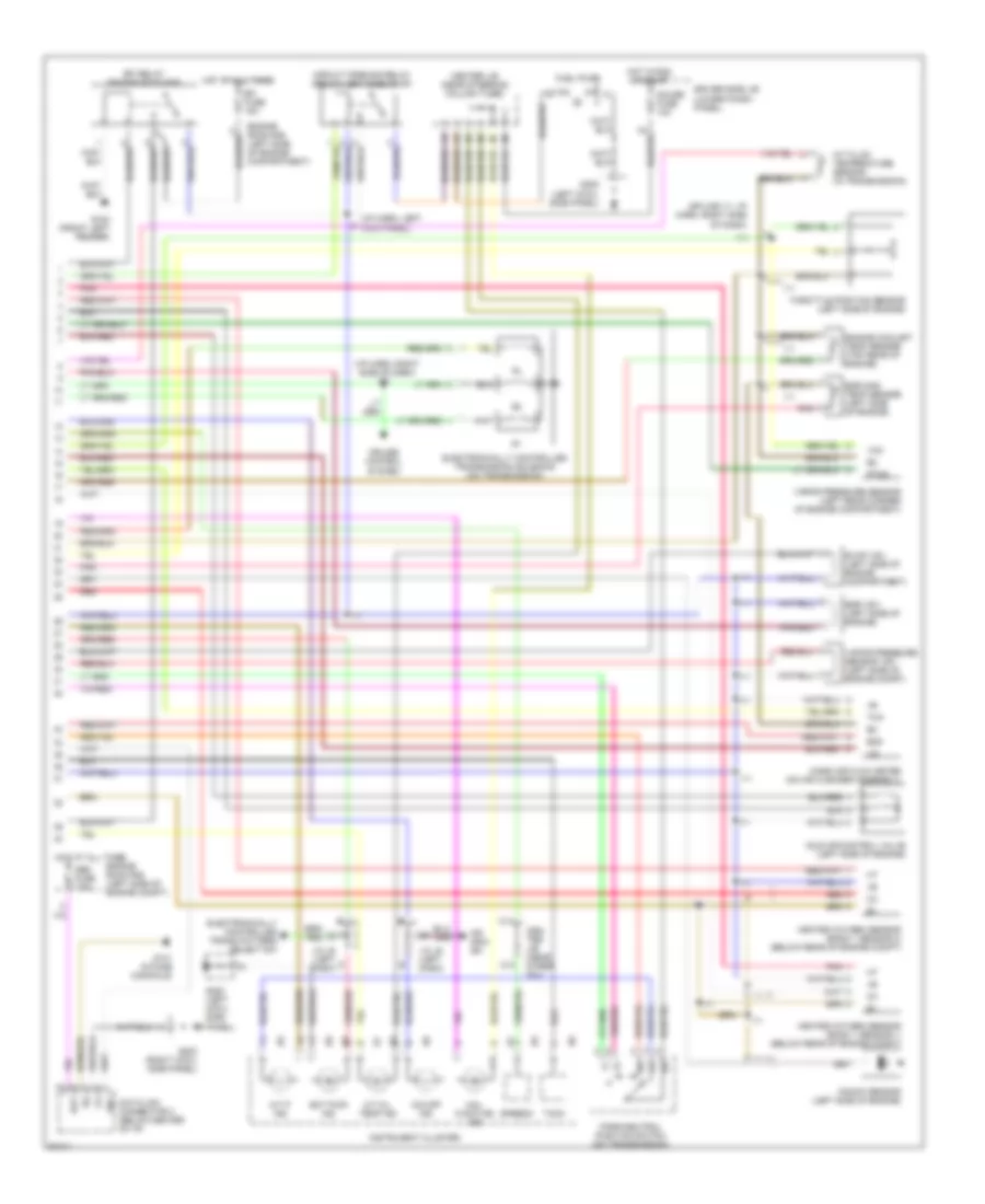
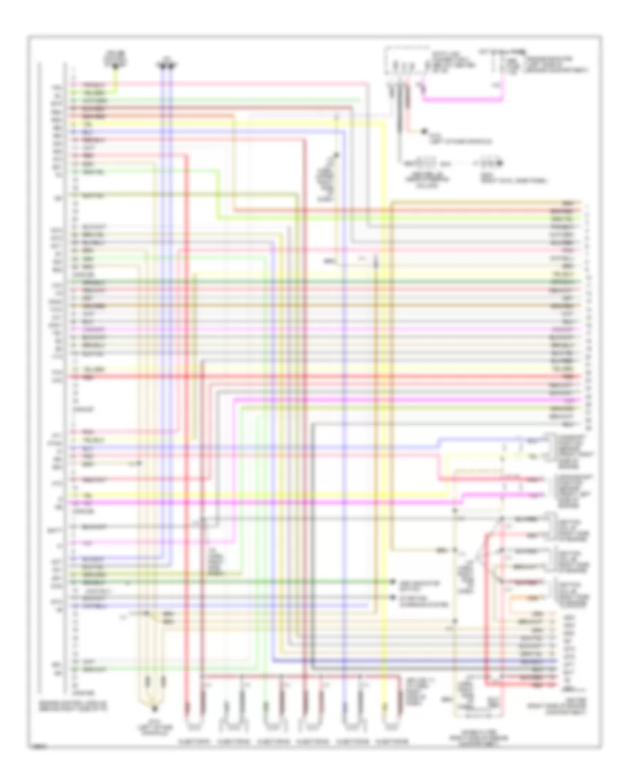
2.7L, Engine Performance Wiring Diagrams (1 of 2) for Toyota 4Runner Limited 1997

List of elements for 2.7L, Engine Performance Wiring Diagrams (1 of 2) for Toyota 4Runner Limited 1997:
- (a/t)
- (eng harn, top left of engine)
- (i/p harn, behind fuse box)
- (near steering column) center j/b
- (right side of dash)
- (splice i11: i/p harn right side of dash)
- 4wd
- A/c system
- Ac1
- Acc
- Act
- Add ind switch (4wd only)
- Batt
- Camshaft position sensor (left center of engine)
- Conn e5
- Conn e6
- Conn e7
- Conn e8
- Crankshaft position sensor (left side of engine)
- Cruise control system
- Data link connector 1 (left side of engine)
- Driver side j/b (lower finish panel)
- E01
- E02
- E03
- Egr
- Els
- Engine control module (right side of i/p, behind glove box)
- Engine room r/b (left side of engine compt)
- Evp
- Exterior lights & defogger systems
- Fuel injector #1
- Fuel injector #2
- Fuel injector #3
- Fuel injector #4
- G112 (left side of engine)
- G119 (right front of engine)
- G131 (intake manifold)
- Gnd
- Hot at all times
- Hot at all times ignition switch
- Ht1
- Ht2
- I11
- I11 (right side of dash)
- Ig-
- Igf
- Ign fuse 7.5a
- Ignition coil 1 & ignitor 1
- Ignition coil 2 & ignitor 2
- Igt
- Igt1
- Igt2
- Inj1
- Inj2
- Inj3
- Inj4
- Knk
- Lock
- Ne-
- Noise filter (right side of engine compt)
- Od1
- Od2
- Oil
- Oil-w
- Ox1
- Ox2
- Pnk
- Ptnk
- Pwr
- Red
- Rsc
- Rso
- Run
- Sdl
- Sp1
- Sp2+
- Sp2-
- Sta
- Start
- Start/ charge system
- Stop fuse 10a
- Stop light switch (on brake pedal support)
- Tach
- Te1
- Tfn
- Thg
- Thw
- Tpc
- Vcc
- Vehicle speed sensor (electronically controlled transmission)
- Vta
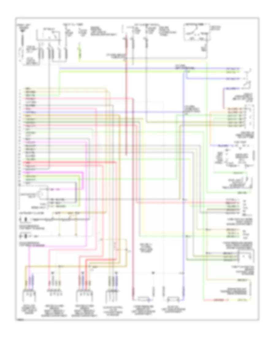
2.7L, Engine Performance Wiring Diagrams (2 of 2) for Toyota 4Runner Limited 1997
List of elements for 2.7L, Engine Performance Wiring Diagrams (2 of 2) for Toyota 4Runner Limited 1997:
- (i/p harn, left kick panel)
- (i/p harn, right side of dash) i11
- (splice i11: i/p harn, right side
- A/t fluid temperature sensor (in transmission)
- A/t oil temp ind
- A/t p ind
- Bat
- C12
- C14
- Cen- ter j/b (near steer col)
- Center j/b (near steering column tube)
- Circuit opening relay (below left side of i/p)
- Cruise control system
- Data link connector 3 (below center of i/p)
- Driver side j/b (lower finish panel)
- E2g
- Ect pwr ind
- Efi fuse 15a
- Efi relay (engine room r/b)
- Egr gas temp sensor (left side of engine)
- Egr vsv (left side of engine)
- Electronically controlled trans pattern select sw
- Electronically controlled transmission solenoid (on transmission)
- Engine coolant temp sensor (top rear of engine)
- Engine room r/b (left side of engine compartment)
- Engine room r/b (left side of engine compt)
- Evap vsv (left side of engine compartment)
- Fuel pump
- G100 (front left fender)
- G131 (intake manifold)
- G200 (left cowl side panel)
- G202 (left cowl side panel)
- G203 (right cowl side panel)
- Gauge fuse 10a
- Heated oxygen sensor (bank 1 sensor 1) (below rear of engine compt)
- Heated oxygen sensor (bank 1 sensor 2) (below rear of engine compt)
- Hot at all times
- Hot in run or start
- I11
- Idle air control valve (left side of engine)
- Instrument cluster
- J/c j6 (left dash)
- Knock sensor (left side of engine)
- Mal- function ind
- Mass air flow meter (on air cleaner assembly)
- O/d main sw
- O/d off ind
- Obd fuse 7.5a
- Of dash)
- Park/neutral position switch (on transmission)
- Pnk
- Ptnk
- Red
- Sdl
- Speedo
- Tach
- Tha
- Throttle position sensor (left side of engine)
- Vapor pressure sensor (left rear corner of engine compartment)
- Vapor pressure sensor vsv (left side of engine compt)
- Vcc
3.4L
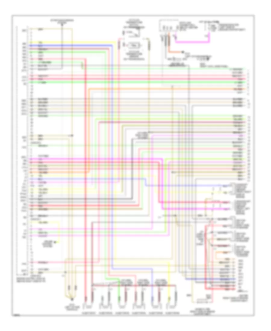
3.4L, Engine Performance Wiring Diagrams, A/T (1 of 3) for Toyota 4Runner Limited 1997
List of elements for 3.4L, Engine Performance Wiring Diagrams, A/T (1 of 3) for Toyota 4Runner Limited 1997:
- #10
- #20
- #30
- #40
- #50
- #60
- (i/p harn, right side of
- (i/p harn, right side of dash)
- A/t fluid temperature sensor (on transmission)
- A/t fluid temperature switch (on transmission)
- Camshaft position sensor (front right side of engine)
- Center j/b (near str col)
- Conn e10
- Conn e11
- Conn e12
- Crankshaft position sensor (front left side of engine)
- Cruise control system
- Dash)
- Data link connector 3 (below center of i/p)
- E02
- E03
- E15
- E22
- Engine control module (behind right side of i/p)
- Engine room r/b (left side of engine compartment)
- Evp
- Ext
- F13
- G131 (left intake manifold)
- G203 (right cowl side panel)
- Gnd
- Hot at all times
- Ht1
- Ht2
- I11
- Idl
- Igc1
- Igc2
- Igc3
- Igf
- Igniter (right side of engine compartment)
- Ignition coil #1 (right side of engine)
- Ignition coil #2 (right side of engine)
- Ignition coil #3 (right side of engine)
- Igt1
- Igt2
- Igt3
- Injector #1
- Injector #2
- Injector #3
- Injector #4
- Injector #5
- Injector #6
- Knk1
- Knk2
- Ne-
- Noise filter (right side of engine compartment)
- Obd fuse 7.5a
- Oil
- Ox1
- Ox2
- Pnk
- Ptnk
- Red
- Rsc
- Rso
- Sdl
- Sp2-
- Sta
- Starting/charging system
- Te1
- Tha
- Thw
- Tpc
- Vcc
- Vta
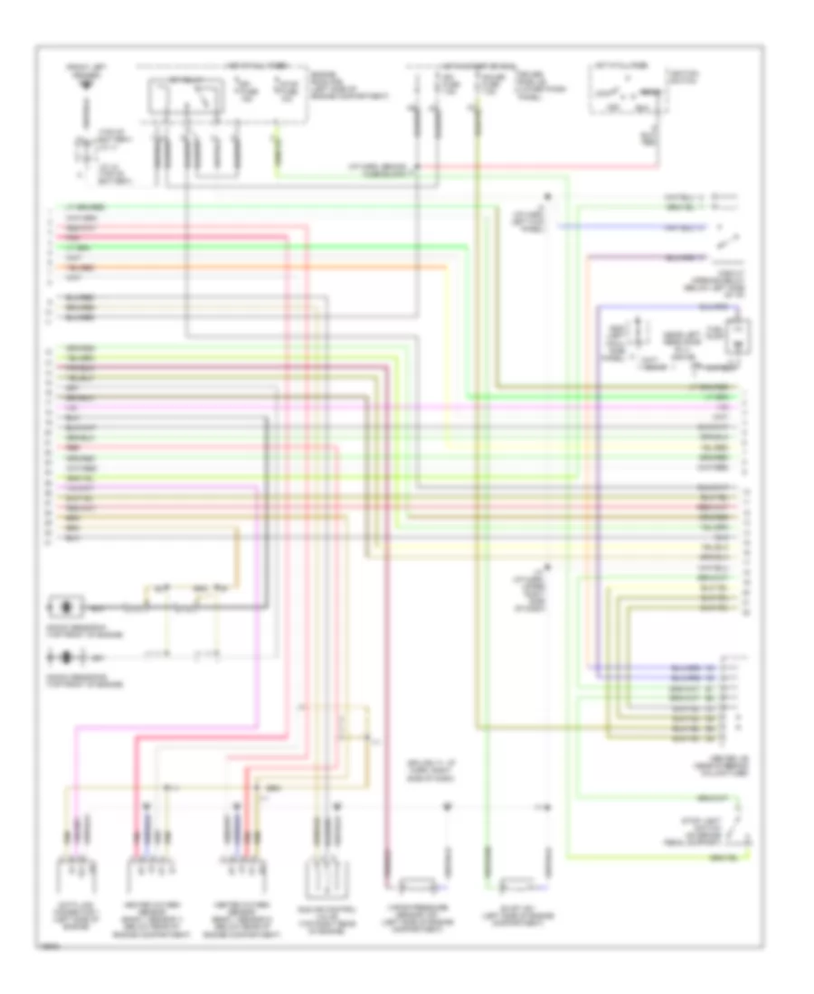
3.4L, Engine Performance Wiring Diagrams, A/T (2 of 3) for Toyota 4Runner Limited 1997
List of elements for 3.4L, Engine Performance Wiring Diagrams, A/T (2 of 3) for Toyota 4Runner Limited 1997:
- (front left fender) g100
- (i/p harn, behind fuse block)
- (near left rear door sill) j/c j12
- (splice i11: i/p harn, right side of dash)
- (top of battery) j/c j1
- Acc
- Center j/b (near steering column tube)
- Circuit opening relay (below left side of i/p)
- Data link connector 1 (left side of engine)
- Driver side j/b (lower finish panel)
- Efi fuse 15a
- Efi relay
- Engine room r/b (left side of engine compartment)
- Evap vsv (left side of engine compartment)
- Fuel pump
- G200 (left cowl side panel)
- Gauge fuse 7.5a
- Heated oxygen sensor (bank 1 sensor 1) (below rear of engine compartment)
- Heated oxygen sensor (bank 1 sensor 2) (below rear of engine compartment)
- Hot at all times
- Hot in start or run
- I10 (i/p harn, upper right side of dash)
- I11
- I2 (i/p harn, left kick panel)
- Idle air control valve (top right rear of engine)
- Ign fuse 7.5a
- Ignition switch
- J/c j2 (top of battery)
- Knock sensor #1 (top front of engine)
- Knock sensor #2 (top front of engine)
- Lock
- Pnk
- Red
- Run
- Start
- Stop fuse 10a
- Stop light switch (on brake pedal support)
- Te1
- Vapor pressure sensor vsv (left side of engine compartment)
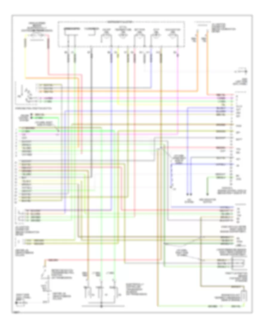
3.4L, Engine Performance Wiring Diagrams, A/T (3 of 3) for Toyota 4Runner Limited 1997
List of elements for 3.4L, Engine Performance Wiring Diagrams, A/T (3 of 3) for Toyota 4Runner Limited 1997:
- (i/p harn, right side of dash)
- (i/p harn, upper right side of dash)
- (right side cowl panel) g203
- 4wd
- A/c system
- A/t oil temperature ind
- A/t p ind
- Ac1
- Act
- Add indicator switch
- Batt
- C12
- C14
- Center j/b (near steering column)
- Conn e13
- Cruise control system
- Detection switch (transfer neutral position) (on transmission)
- E15
- Ect pwr ind
- Electroniclly controlled transmission solenoid (on transmission)
- Engine control module (behind right side of i/p)
- Engine coolant temperature sensor (rear of engine)
- G200 (left side cowl panel)
- I10
- I11
- Instrument cluster
- J5 junction connector (behind combination meter)
- J6 junction connector (behind combination meter)
- Malfunction ind
- Mass air flow meter (right side of engine compartment)
- O/d off ind
- Od1
- Od2
- Oil-w
- Park/neutral position switch
- Ptnk
- Pwr
- Sdl
- Sp1
- Speedometer
- Tachometer
- Tfn
- Tha
- Throttle position sensor (top right side of engine)
- Vapor pressure sensor (right rear corner of engine compartment)
- Vcc
- Vehicle speed sensor (electronically controlled transmission)
3.4L, Engine Performance Wiring Diagrams, M/T (1 of 2) for Toyota 4Runner Limited 1997
List of elements for 3.4L, Engine Performance Wiring Diagrams, M/T (1 of 2) for Toyota 4Runner Limited 1997:
- #10
- #20
- #30
- #40
- #50
- #60
- (i/p harn, right side dash)
- (i/p harn, right side of dash)
- (splice i11: i/p harn, right side of dash)
- 4wd
- 4wd only
- A/c system
- Ac1
- Act
- Add indicator switch
- Batt
- Camshaft position sensor (front right side of engine)
- Center j/b (near steering
- Column)
- Conn e6
- Conn e7
- Conn e8
- Conn e9
- Crankshaft position sensor (front left side of engine)
- Cruise control system
- Data link connector 3 (below center of i/p)
- E01
- E02
- E03
- E15
- E22
- Engine control module (behind right side of i/p)
- Engine room r/b (left side of engine compartment)
- Evp
- Ext
- G131 (left intake manifold)
- G203 (right cowl side panel)
- Gnd
- Hot at all times
- Ht1
- Ht2
- I10 (i/p harn, upper right side of dash)
- I11
- Idl
- Igc1
- Igc2
- Igc3
- Igf
- Igniter (right side of engine compartment)
- Ignition coil #1 (right side of engine)
- Ignition coil #2 (right side of engine)
- Ignition coil #3 (right side of engine)
- Igt1
- Igt2
- Igt3
- Injector #1
- Injector #2
- Injector #3
- Injector #4
- Injector #5
- Injector #6
- Knk1
- Knk2
- Ne-
- Noise filter (right side of engine compartment)
- Obd fuse 7.5a
- Ox1
- Ox2
- Pnk
- Ptnk
- Red
- Rsc
- Rso
- Sdl
- Sp1
- Sta
- Starting/ charging system
- Te1
- Tha
- Thw
- Tpc
- Vcc
- Vta
3.4L, Engine Performance Wiring Diagrams, M/T (2 of 2) for Toyota 4Runner Limited 1997
List of elements for 3.4L, Engine Performance Wiring Diagrams, M/T (2 of 2) for Toyota 4Runner Limited 1997:
- (front left fender) g100
- (i/p harn, behind fuse block) i3
- (i/p harn, left kick panel)
- (i/p harn, upper right side of dash) i10
- (near left rear door sill) j/c j12
- (splice i11: i/p harn, right side of dash)
- (top of battery j/c j1
- Acc
- Center j/b (near steering column tube)
- Circuit opening relay (below left side of i/p)
- Data link connector 1 (left side of engine)
- Driver side j/b (lower finish panel)
- Efi fuse 15a
- Efi relay
- Engine coolant temperature sensor (rear of engine)
- Engine room r/b (left side of engine compartment)
- Evap vsv (left side of engine compartment)
- Fuel pump
- G200 (left cowl side panel)
- Gauge fuse 7.5a
- Heated oxygen sensor (bank 1 sensor 1) (below rear of engine compartment)
- Heated oxygen sensor (bank 1 sensor 2) (below rear of engine compartment)
- Hot at all times
- Hot in start or run
- I11
- Idle air control valve (top right rear of engine)
- Ign fuse 7.5a
- Ignition switch
- Instrument cluster
- J/c j2 (top of battery)
- Knock sensor #1 (top front of engine)
- Knock sensor #2 (top front of engine)
- Lock
- Malfunction ind lp
- Mass air flow meter (right side of engine compartment)
- Pnk
- Ptnk
- Red
- Run
- Speed input
- Start
- Stop fuse 10a
- Stop light switch (on brake pedal support)
- Tach
- Te1
- Tha
- Throttle position sensor (top right side of engine)
- Vapor pressure sensor (right rear corner of engine compartment)
- Vapor pressure sensor vsv (left side of engine compartment)
- Vcc