ENGINE PERFORMANCE
4.0L
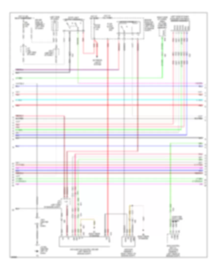
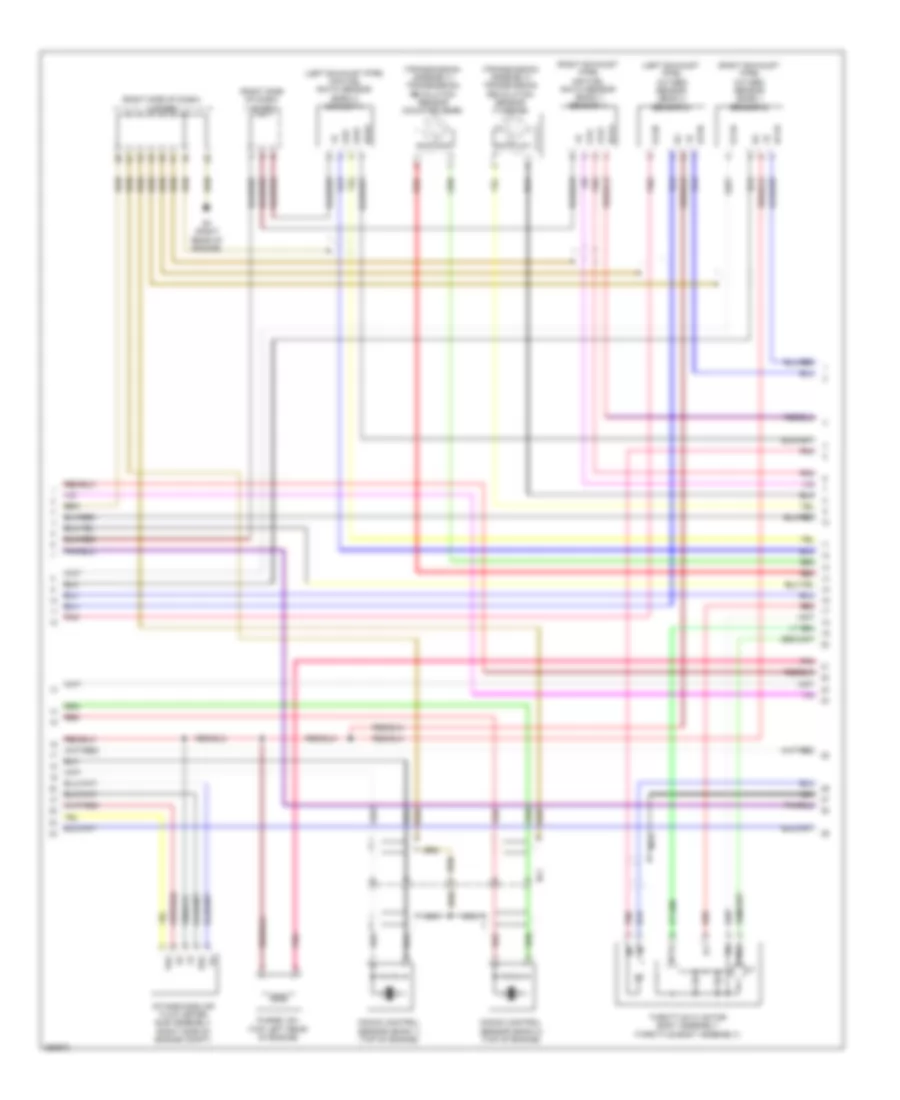
4.0L, Engine Performance Wiring Diagram (1 of 7) for Toyota 4Runner Trail 2013

List of elements for 4.0L, Engine Performance Wiring Diagram (1 of 7) for Toyota 4Runner Trail 2013:
- (left front of engine compt) a1
- (left side of engine compt) j/c a38
- +b2
- +bl
- 4wd
- A/f fuse 20a
- A/f relay
- Ab1
- Ac1
- Act
- Ai-vsv relay
- Aip
- Aip2
- Air conditioning system
- Air conditioning system computer data lines system
- Air pmp htr fuse 10a
- Anti-theft system
- Ao1
- B2 (right rear of engine)
- Batt
- Bf1
- Bf2
- Canh
- Canl
- Cann
- Canp
- Ccs
- Computer data lines system
- Cruise control system
- E22
- Ecm (right end of dash)
- Efi 2 fuse 7.5a
- Efi fuse 25a
- Efi main relay
- Els2
- Engine room j/b assembly (left side of engine compt)
- Engine room r/b assembly (left side of engine compt)
- Epa
- Epa2
- F50
- F51
- F81
- Fa1
- Fa2
- Fo1
- Fp-
- Fpc
- Fuel pump (fuel tank)
- Fuel pump control ecu assembly (left side of luggage compt)
- Gnd
- Gndl
- Hot at all times
- Igsw
- Imi
- Imo
- J/c a39 (left side of engine compt)
- J/c f57 (right end of dash)
- Left air switching valve assembly (left rear of engine)
- Mpmp
- Mrel
- Neo
- O1 (left "b" pillar)
- Pnk
- Power management control ecu (w/ smart key system) (center of dash)
- Qo3
- Red
- Right air switching valve assembly (right rear of engine)
- Sftd
- Sftu
- Spd
- St1-
- Sta
- Starting/charging system
- Stp
- Tach
- Tfn
- Vc2
- Vcp2
- Vcpa
- Vpa
- Vpa2
- Vpmp
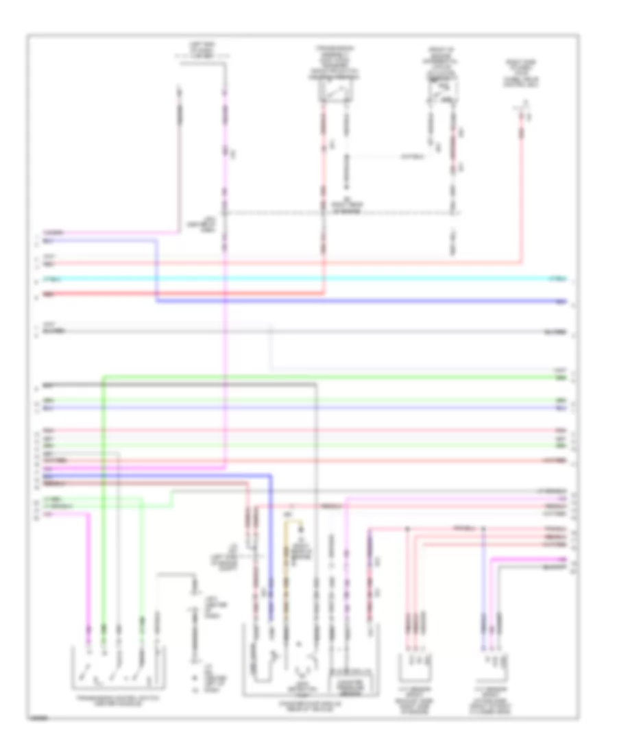
4.0L, Engine Performance Wiring Diagram (2 of 7) for Toyota 4Runner Trail 2013
List of elements for 4.0L, Engine Performance Wiring Diagram (2 of 7) for Toyota 4Runner Trail 2013:
- (left side of dash) accelerator pedal sensor assembly
- (left side of dash) j/b 4
- (right side of cargo area) voltage inverter assembly
- A44
- A45
- A49
- A66
- Ab1
- Air injecton control driver (left rear of engine compt)
- Air pmp fuse 50a
- Air pmp htr relay
- Air pump assembly (right front of engine compt)
- Aph+
- Aphg
- B1 (right rear of engine)
- B10
- B2 (right rear of engine)
- B27
- Batt
- Bf1
- Bf2
- C15
- C51
- Canh
- Canl
- Computer data lines system
- D26
- Driver side j/b assembly (left end of dash)
- Engine room r/b assembly (left side of engine compt)
- Epa
- Epa2
- Excd
- Exterior lights system
- Fa1
- Fa2
- Fn1
- Gnd
- Hot at all times
- Hot w/ ig2 relay energized
- Ign fuse 10a
- J/b 5 (center of dash)
- J/c a36 (left end of dash)
- J/c a37 (left side of engine compt)
- J/c f64 (center left of dash)
- N19
- Pnk
- Red
- Sip
- Siv
- Skid control ecu w/ actuator assembly (left rear of engine compt)
- Sp1
- Stop fuse 10a
- Stop light switch assembly
- Vcp2
- Vcpa
- Vpa
- Vpa2
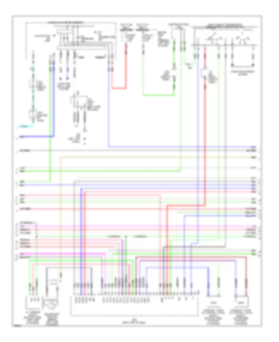
4.0L, Engine Performance Wiring Diagram (3 of 7) for Toyota 4Runner Trail 2013
List of elements for 4.0L, Engine Performance Wiring Diagram (3 of 7) for Toyota 4Runner Trail 2013:
- (front of engine) differential vacuum actuator assembly
- (left end of dash) j/c a36
- (right side of dash) four wheel drive control ecu
- (transmission assembly) (4wd (vf2a)) transfer indicator switch (neutral position)
- A16
- A65
- Ab1
- Add
- Ao1
- B1 (right rear of engine)
- B2 (right rear of engine)
- B50
- B54
- Bd1
- Bf1
- Bf2
- C54
- Canister pressure sensor
- Canister pump module (rear of vehicle)
- Ex+
- Ex-
- F47
- Fa2
- Fo1
- Gnd
- J/b 5 (center of dash)
- J/c a37 (left side of engine compt)
- J/c f64 (center left of dash)
- Leak detection pump
- Mgnd
- Mtrb
- Pnk
- Red
- Sftd
- Sftu
- Sgnd
- Transmission control switch (center console)
- Vc2
- Vcc
- Vent valve
- Vgnd
- Vlvb
- Vout
- Vvr+
- Vvr-
- Vvt sensor (bank1 exhaust side) (right side of engine)
- Vvt sensor (bank1 intake side) (front of right cylinder head)
4.0L, Engine Performance Wiring Diagram (4 of 7) for Toyota 4Runner Trail 2013
List of elements for 4.0L, Engine Performance Wiring Diagram (4 of 7) for Toyota 4Runner Trail 2013:
- (center of dash) j/b 5
- (right side of transmission) park/neutral position switch
- A/t oil temperature ind
- A64
- Airv
- B20
- B25
- B35
- B36
- B59
- Bf2
- Buzzer
- C16
- C20
- C31
- C55
- C57
- Camshaft timing oil control valve (bank 2 exhaust side) (top right of engine)
- Camshaft timing oil control valve (bank 2 intake side) (top right of engine)
- Canh
- Canl
- Chk
- Combination meter assembly
- Computer data lines system
- Crankshaft position sensor (left side of engine)
- Driver side j/b assembly (left end of dash)
- Ecm (right end of dash)
- Ecu ig 1 fuse 10a
- Ev1+
- Ev1-
- Ev2+
- Ev2-
- Ex+
- Ex-
- Ex1b
- Ex2b
- F56
- Gauge fuse 7.5a
- Hot w/ ig 1 relay energized
- Hot w/ ig2 relay energized
- Ig+
- J/b 4 (left side of dash)
- J/b 5 (center of dash)
- J/c b48 (right side of dash)
- J/c f55 & f56 (left side f55 of dash)
- J/c f63 (left kick panel)
- Lcd
- Malfunction ind lamp
- Mgnd
- Ne+
- Ne-
- Oc2+
- Oc2-
- Oe2+
- Oe2-
- Oil pressure ind
- Ox1b
- Ox2b
- Pnk
- Red
- Starting/charging system
- Vc2
- Vcv1
- Vcv2
- Vv1+
- Vv1-
- Vv2+
- Vv2-
- Vvt sensor (bank 2 exhaust side) (left side of engine)
4.0L, Engine Performance Wiring Diagram (5 of 7) for Toyota 4Runner Trail 2013
List of elements for 4.0L, Engine Performance Wiring Diagram (5 of 7) for Toyota 4Runner Trail 2013:
- (transmission assembly) electronically controlled transmission solenoid
- A68
- Aidi
- Airp
- Alt
- B14
- B22
- B37
- Camshaft timing oil control valve (bank 1 exhaust side) (top left of engine)
- Camshaft timing oil control valve (bank 1 intake side) (top left of engine)
- D39
- Driver side j/b assembly (left end of dash)
- E2g
- Ecm (right end of dash)
- Ecu-b fuse 10a
- Ekn2
- Eknk
- Engine room r/b assembly (left side of engine compt)
- Etha
- Ethw
- Hot at all times
- Igt6
- J/b 4 (left side of dash)
- Knk1
- Knk2
- Nsw
- Oc1+
- Oc1-
- Oe1+
- Oe1-
- Ot+
- Ot-
- Ot2+
- Ot2-
- Pnk
- Power steering oil pressure switch (right front of engine compt)
- Ppmp
- Psp
- Red
- Sl1+
- Sl1-
- Sl2+
- Sl2-
- Slt+
- Slt-
- Slu+
- Slu-
- Starting/ charging system
- Tha
- Vvl+
- Vvl-
- Vvt sensor (bank 2 intake side) (front of left cylinder head)
4.0L, Engine Performance Wiring Diagram (6 of 7) for Toyota 4Runner Trail 2013
List of elements for 4.0L, Engine Performance Wiring Diagram (6 of 7) for Toyota 4Runner Trail 2013:
- (left exhaust pipe) air fuel ratio sensor (bank 2 sensor 1)
- (left exhaust pipe) oxygen sensor (bank 2 sensor 2)
- (right exhaust pipe) air fuel ratio sensor (bank 1 sensor 1)
- (right exhaust pipe) oxygen sensor (bank 1 sensor 2)
- (right side of dash) j/c b48
- (right side of dash) j/c b49
- (transmission assembly) transmission revolution sensor (counter gear)
- (transmission assembly) transmission revolution sensor (turbine)
- A1a+
- A1a-
- A2a+
- A2a-
- B1 (right rear of engine)
- Be1
- E2g
- Ha1a
- Ha2a
- Ht1b
- Ht2b
- Intake mass air flow meter sub assembly (right side of engine compt)
- Knock control sensor (bank 1) (top of engine)
- Knock control sensor (bank 2) (top of engine)
- Nca
- Ox1b
- Ox2b
- Pnk
- Purge vsv (top left rear of engine)
- Red
- Tha
- Throttle w/ motor body assembly (throttle body assembly)
- Vta
- Vta2
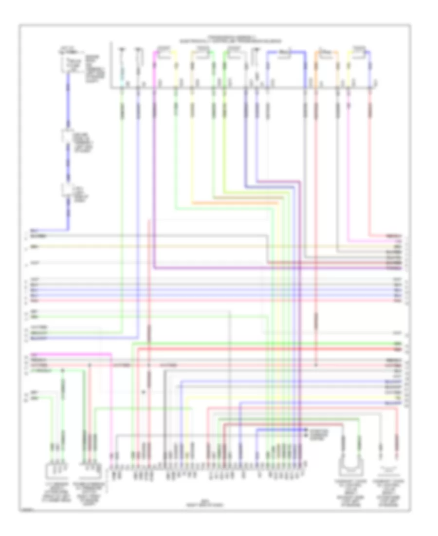
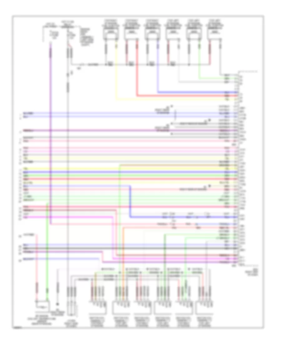
4.0L, Engine Performance Wiring Diagram (7 of 7) for Toyota 4Runner Trail 2013
List of elements for 4.0L, Engine Performance Wiring Diagram (7 of 7) for Toyota 4Runner Trail 2013:
- (top left of engine) fuel injector assembly 2
- (top left of engine) fuel injector assembly 4
- (top left of engine) fuel injector assembly 6
- (top right of engine) fuel injector assembly 1
- (top right of engine) fuel injector assembly 3
- (top right of engine) fuel injector assembly 5
- +bm
- A1a+
- A1a-
- A2a+
- A2a-
- Ab1
- Air1
- B1 (right rear of engine)
- B2 (right rear of engine)
- B38
- B39
- Bf1
- Bf2
- E01
- E02
- E03
- E04
- E05
- Ecm (right end of dash)
- Efi engine coolant temperature sensor (rear of engine)
- Engine room r/b assembly (left side of engine compt)
- Eta
- Etcs fuse 10a
- Fa1
- Fa2
- Ge01
- Gnd
- Ha1a
- Ha2a
- Hai1
- Hot at all times
- Hot w/ ig2 relay energized
- Ht1b
- Ht2b
- Igf
- Igf1
- Ignition coil assembly 1 (top left of engine)
- Ignition coil assembly 2 (top right of engine)
- Ignition coil assembly 3 (top left of engine)
- Ignition coil assembly 4 (top right of engine)
- Ignition coil assembly 5 (top left of engine)
- Ignition coil assembly 6 (top right of engine)
- Igt1
- Igt2
- Igt3
- Igt4
- Igt5
- Igt6
- Inj fuse 10a
- J/c b48 (right side of dash)
- Me01
- Nca
- Nt+
- Nt-
- Pnk
- Prg
- Red
- Sl1+
- Sl1-
- Sl2-
- Sp2+
- Sp2-
- Tho1
- Tho2
- Thw
- Vcta
- Vta1
- Vta2