ENGINE PERFORMANCE
3.0L
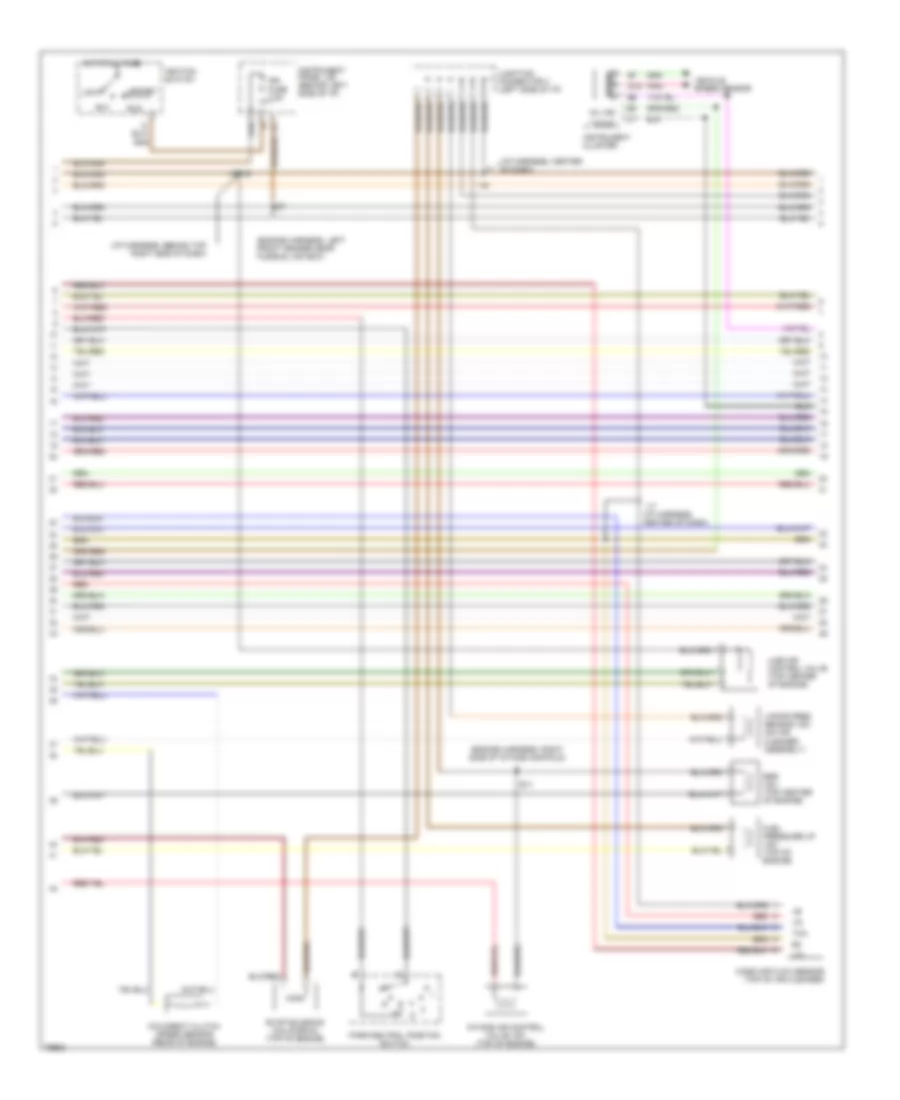
3.0L, Engine Performance Wiring Diagrams (1 of 3) for Toyota Avalon XLS 1996

List of elements for 3.0L, Engine Performance Wiring Diagrams (1 of 3) for Toyota Avalon XLS 1996:
- #10
- #20
- #30
- #40
- #50
- #60
- (behind right side of i/p)
- (engine harness, center of intake manifold)
- (engine harness, left side of intake manifold )
- (engine harness, left side of intake manifold)
- (i/p harness, behind center of dash)
- (left side of engine compartment)
- Acis
- Conn e6
- Conn e7
- Conn e8
- E01
- E02
- E03
- E10
- Efi fuse 15a
- Efi main relay
- Egr
- Engine control module (ecm)
- Engine room j/b
- Evp1
- F12
- Fpu
- G100 (front left fender)
- G131 (left intake manifold)
- G22+
- Hot at all times
- Hot in start
- Htl
- Htr
- I17
- Idl
- Igf
- Igt2
- Igt3
- Igt4
- Injector #1
- Injector #2
- Injector #3
- Injector #4
- Injector #5
- Injector #6
- Instrument panel j/b (behind left side of i/p)
- Knkl
- Knkr
- Nc2+
- Nc2-
- Ne+
- Ne-
- Nsw
- Oxl
- Oxr
- Pnk
- Ptnk
- Red
- Rsc
- Rso
- Sln-
- Sta
- Starter fuse 5a
- Te1
- Tha
- Thg
- Thw
- Tpc
- Transmission system
- Vapor pressure sensor (center of safety wall)
- Vg-
- Vta
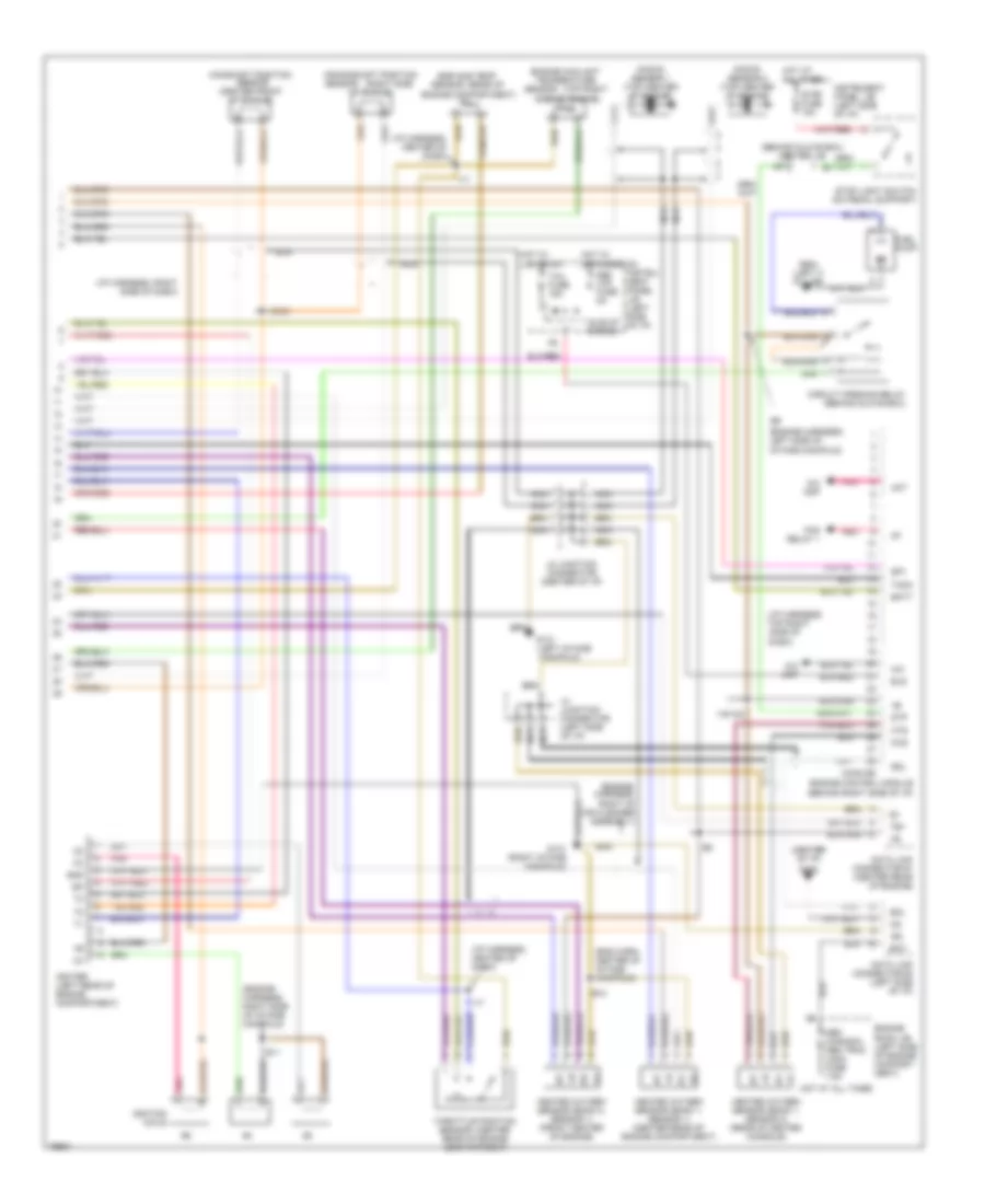
3.0L, Engine Performance Wiring Diagrams (2 of 3) for Toyota Avalon XLS 1996
List of elements for 3.0L, Engine Performance Wiring Diagrams (2 of 3) for Toyota Avalon XLS 1996:
- (engine harness, left front fender near fusible link box)
- (engine harness, right side of intake manifold)
- (i/p harness, behind top right side of dash)
- (i/p harness, center of dash)
- Acc
- C16
- D10
- E11
- Egr vsv (top center of engine)
- Evap solenoid (california) (top of engine)
- Fuel pressure up vsv (top of engine)
- Hot at all times
- I16
- I17 (i/p harness, center of dash)
- I19/i20
- Ign fuse 7.5a
- Ignition switch
- Ilde air control valve (top center of engine)
- Instrument cluster
- Instrument panel j/b (behind left side of i/p)
- Intake air control valve vsv (top of engine)
- Junction connector 3 (left side of i/p)
- Lock
- Mass air flow sensor (top of air cleaner)
- Mil ind
- O/d direct clutch speed sensor (rear of engine)
- Park/neutral position switch
- Pnk
- Red
- Run
- Speed
- Start
- Tacho
- Tha
- Vapor pres sensor vsv (on air cleaner assembly)
- Vehicle speed sensor
- Vg-
3.0L, Engine Performance Wiring Diagrams (3 of 3) for Toyota Avalon XLS 1996
List of elements for 3.0L, Engine Performance Wiring Diagrams (3 of 3) for Toyota Avalon XLS 1996:
- (behind glove box) center j/b
- (behind right side of i/p)
- (center
- (center of i/p)
- (eng harn, center of intake manifold)
- (engine harness, left side of intake manifold)
- (engine harness, right side of intake manifold)
- (engine, harness, right of air cleaner assembly)
- (i/p harness,
- (i/p harness, center of dash)
- (i/p harness, right side of dash)
- (left intake
- (rear of
- (right side
- (top right
- +b +b
- A/c
- A/c amp
- Act
- Bat
- Batt
- Camshaft position sensor (center front of engine)
- Circuit opening relay (behind glove box)
- Conn e5
- Crankshaft position
- Dash)
- Data link connector #1 (center rear of engine)
- Data link connector #3 (left side of i/p)
- Def i/up fuse 5a
- Defogger on
- E10
- E11
- Egr gas temp
- Els
- Engine compartment)
- Engine control module
- Engine coolant temperature
- Engine room j/b (left side of engine compart- ment)
- Fan relay 1
- Fuel pump
- G131
- G131 (right intake manifold)
- G206
- G904 (left c pillar)
- Gnd
- Heated oxygen sensor (bank 1, sensor 1) (center rear of engine compartment)
- Heated oxygen sensor (bank 1, sensor 2) (rear of center console)
- Heated oxygen sensor (bank 2, sensor 1) (front center of engine)
- Hot at all times
- Hot w/
- Ht ht
- Hts
- I17
- I18/i21
- I19/120
- Idle-up diodes
- Igf
- Igniter (left rear of engine compartment)
- Ignition coils
- Instru- ment panel j/b (left side of i/p)
- Instrument panel j/b (left side of i/p)
- J2 junction connector (center of i/p)
- J4 junction connector (left side of i/p)
- Knock sensor 1 (top center of engine)
- Knock sensor 2 (top center of engine)
- Lights on
- Manifold)
- Nca
- Obd (canada) obd trac (usa) fuse 7.5a
- Of engine)
- Ox ox
- Oxs
- Pnk
- Rear of engine compartment)
- Red
- Sdl
- Sensor
- Side of engine)
- Sp1
- Stop fuse 15a
- Stop light switch (on pedal support)
- Stp
- Taco
- Tail fuse 15a
- Te1
- Throttle position
- Top right side of