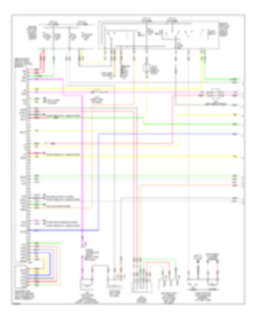
ENGINE PERFORMANCE
2.4L
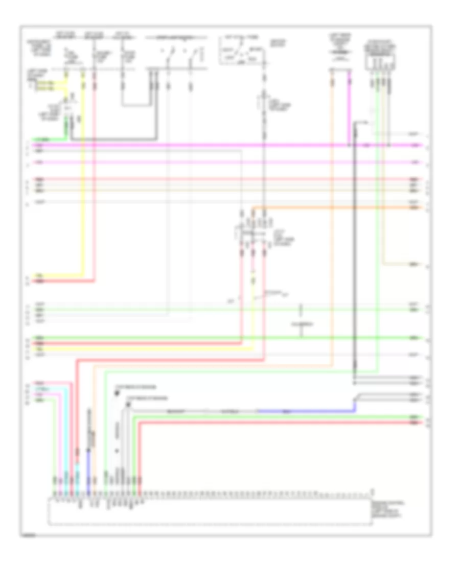
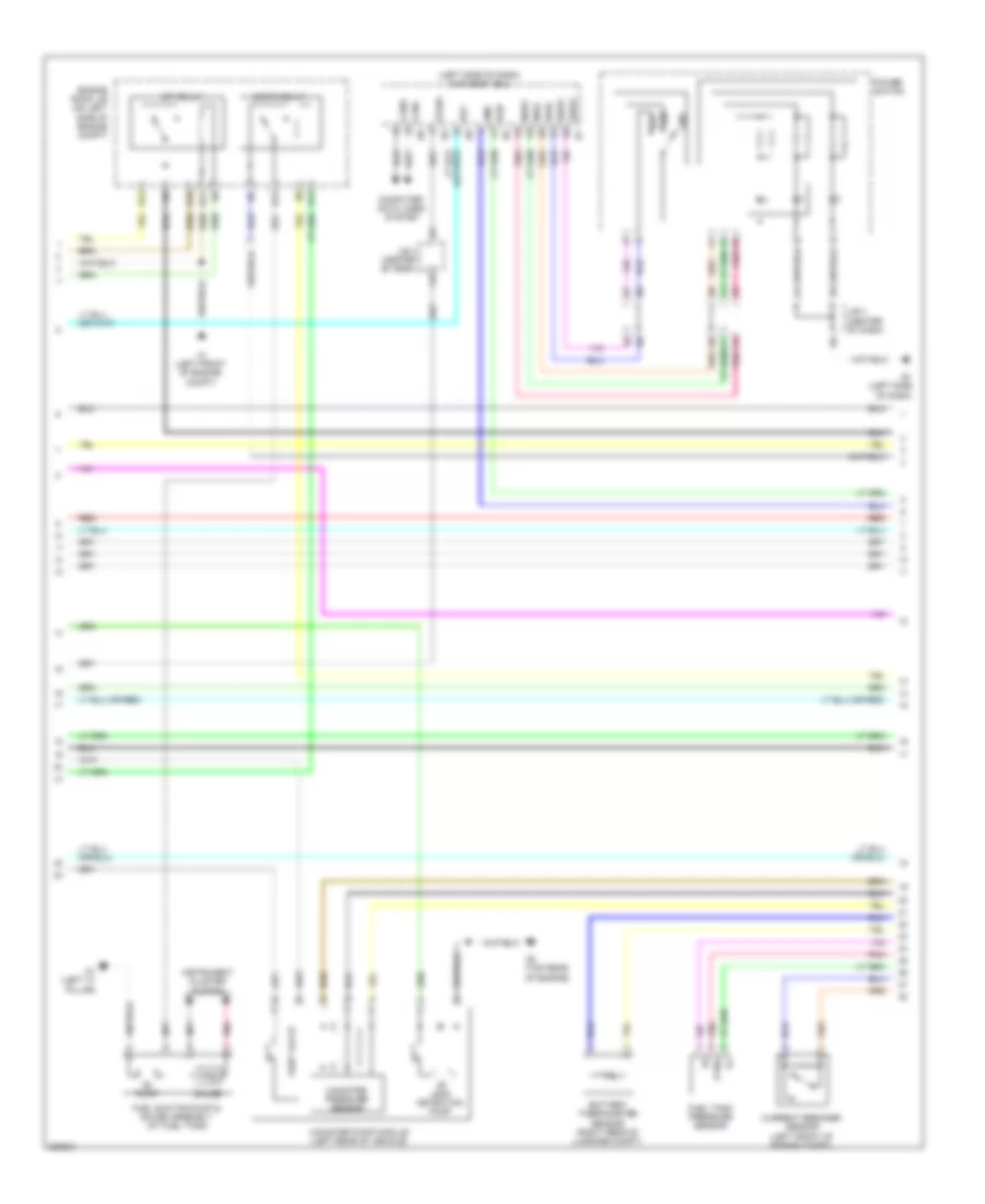
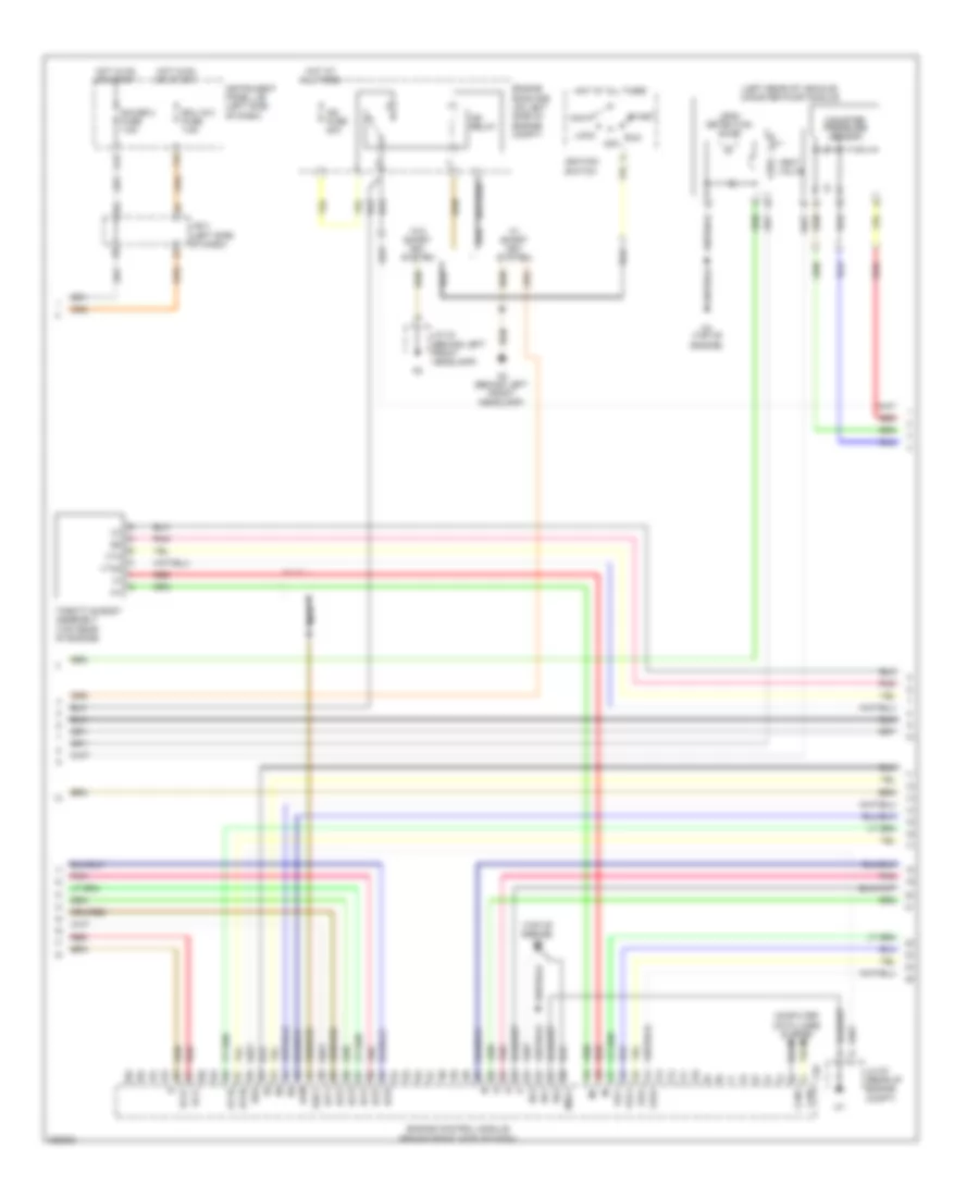
2.4L, Engine Controls Wiring Diagram (1 of 4) for Toyota Camry 2008

List of elements for 2.4L, Engine Controls Wiring Diagram (1 of 4) for Toyota Camry 2008:
- (at fuel tank) fuel suction pump & gauge assembly
- (california)
- (left front of engine compt)
- (left side of dash) a3
- (left side of engine compt) engine control module
- +b2
- +bm
- A24
- A41
- A41 j/c 41 & 42 (left side of dash)
- A42
- Accelerator position sensor (on accelerator pedal assembly)
- Anti-theft system
- B10
- Batt
- C/opn relay
- Canh
- Canl
- Ccs
- Clutch start switch (m/t) (behind left side of dash)
- Computer data lines system
- Cooling fans system
- Cruise control system
- D12
- E10
- E11
- E12
- E13
- Efi 1 fuse 10a
- Efi 2 fuse 15a
- Efi 3 fuse 10a
- Efi main fuse 30a
- Efi relay
- Engine room j/b (on left side of engine compt)
- Engine room r/b (on left side of engine compt)
- Eom
- Epa
- Epa2
- Etcs fuse 10a
- Fanh
- Fanl
- Gauge
- Hot at all times
- Iac+
- Iac-
- Igsw
- Ill+
- Ill-
- Imi
- Imo
- Instrument cluster system
- Interior lights system
- J/b 3 (left side of dash)
- J/c 41 (right side of dash)
- Mpmp
- Mrel
- N1 (left "c" pillar)
- P r
- Park/neutral position switch (a/t) (0n transaxle)
- Pnk
- Power steering oil pressure switch (near front of engine)
- Psw
- Pump
- Red
- Spd
- St1-
- Sta
- Starting/charging system
- Stp
- Tach
- Transmission control switch
- Vcp2
- Vcpa
- Vpa
- Vpa2
- Vpmp
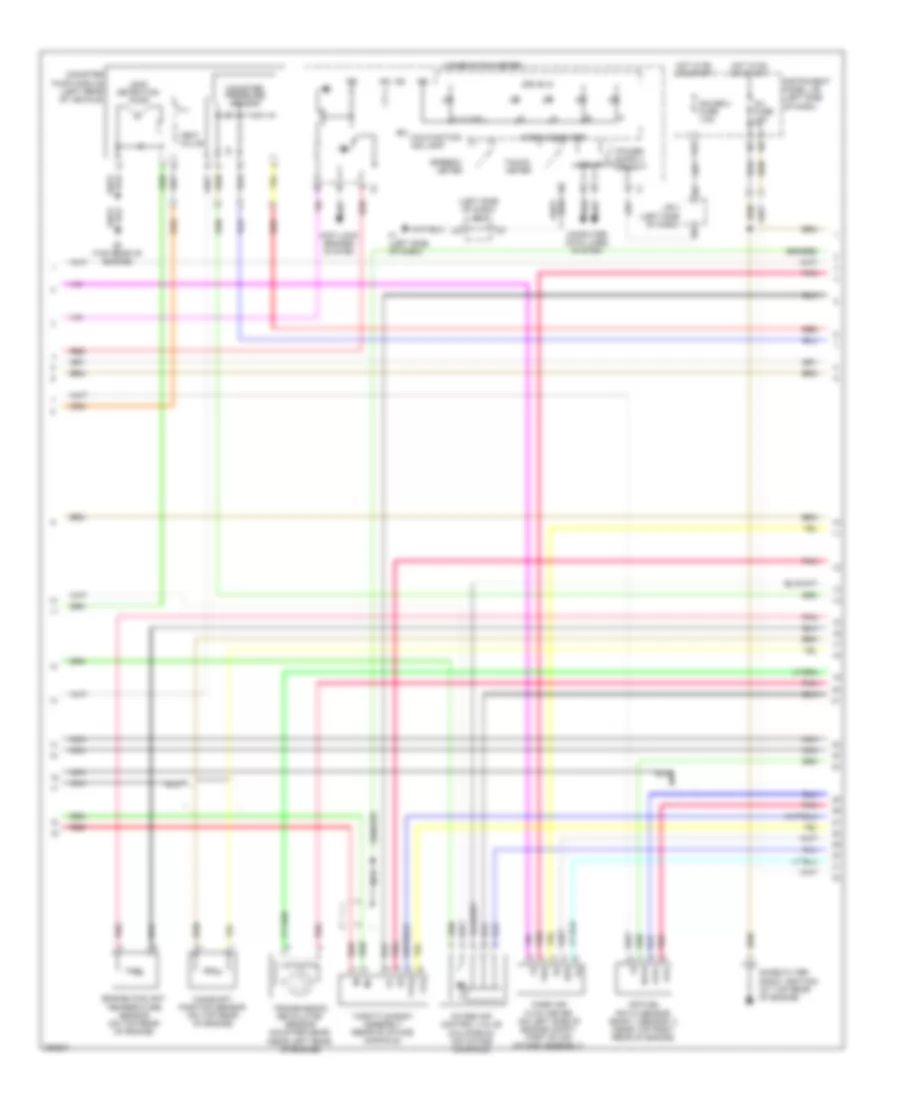
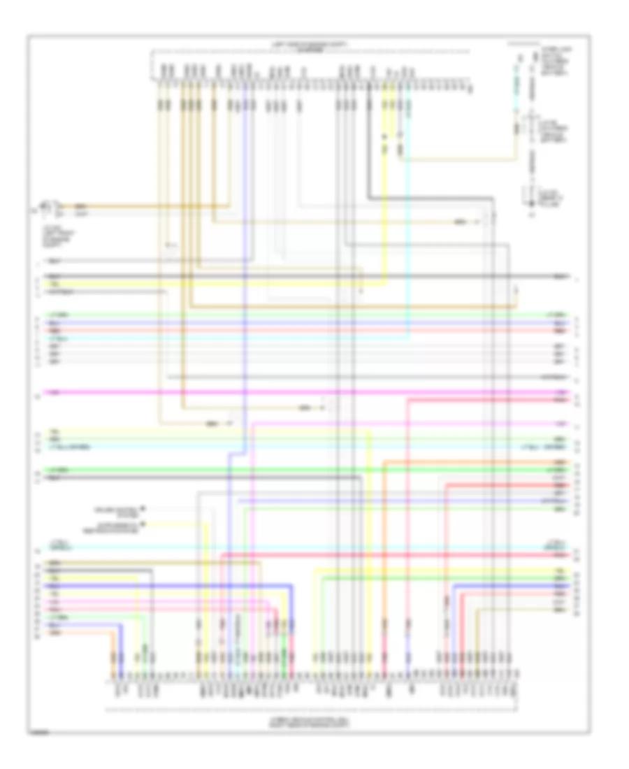
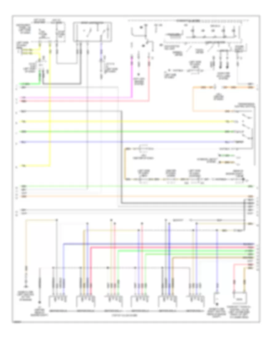
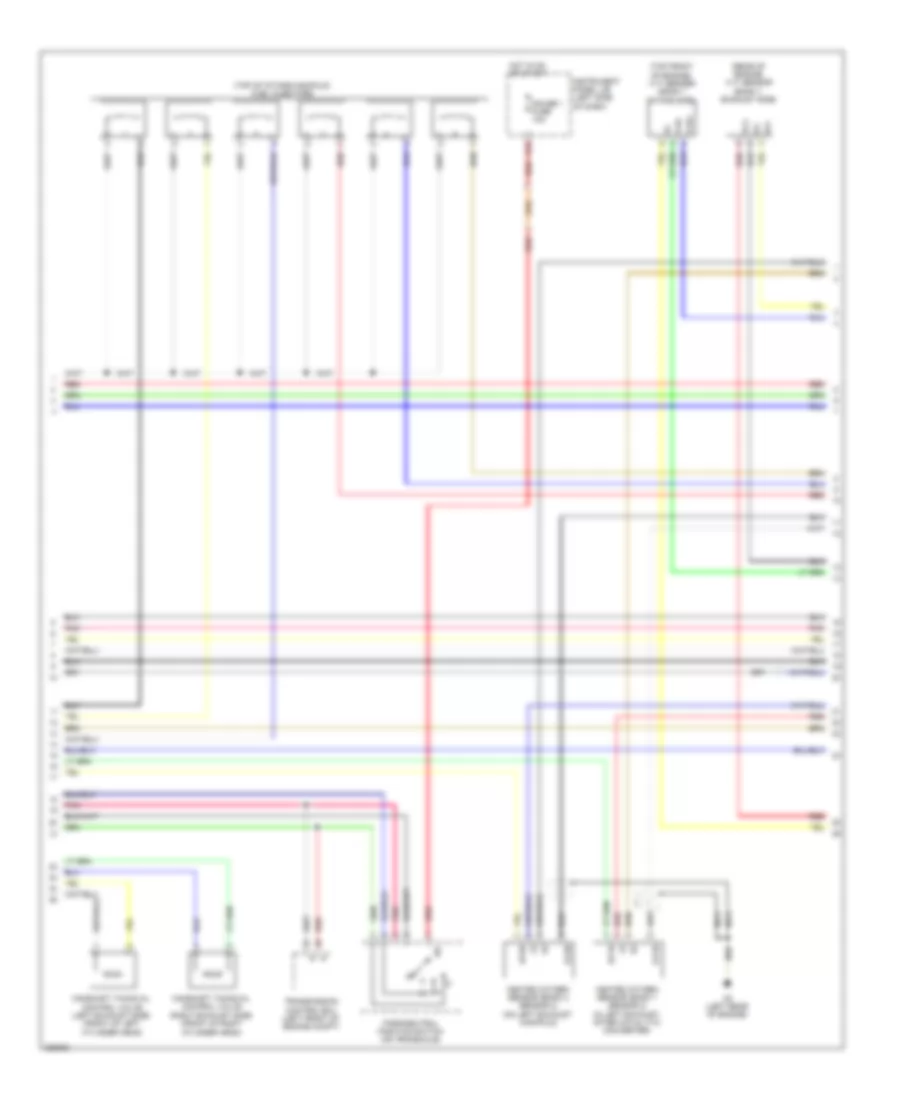
2.4L, Engine Controls Wiring Diagram (2 of 4) for Toyota Camry 2008
List of elements for 2.4L, Engine Controls Wiring Diagram (2 of 4) for Toyota Camry 2008:
- (in exhaust) heated oxygen sensor (bank 1 sensor 2)
- (left rear of engine compt) vsv (purge)
- (left side of dash) j/b 3
- (top rear of engine) c4
- (top rear of engine) c6
- A/t
- A41
- A42
- A58
- Acc
- Alt
- C24
- California
- E01
- E02
- E04
- E40
- Engine control module (left side of engine compt)
- F12
- Gauge 1 fuse 10a
- H16
- Hot at all times
- Hot in on or start
- Ht1b
- Ign fuse 10a
- Ignition switch
- Instrument panel j/b (left side of dash)
- J/b 3 (left side of dash)
- J/c 40 & 58 (left side of dash)
- J/c 41 & 42 (left side of dash)
- K12
- Lock
- M/t
- Me01
- Nca
- Nsw
- Off
- Ox1b
- Pnk
- Prg
- Red
- Run
- Start
- Stop fuse 10a
- Stop lamp switch
- System starting/charging
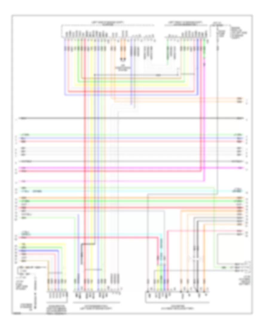
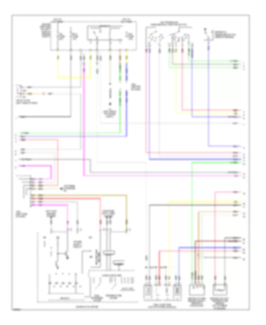
2.4L, Engine Controls Wiring Diagram (3 of 4) for Toyota Camry 2008
List of elements for 2.4L, Engine Controls Wiring Diagram (3 of 4) for Toyota Camry 2008:
- (left side of dash) j/b 3
- (top rear of engine)
- 4, 3, 2 & l
- A1a+
- A1a-
- Air fuel ratio sensor (bank 1 sensor 1) (near top right rear of engine)
- Anti-lock brakes system
- Camshaft position sensor (on top rear of engine)
- Can i/f
- Canister pressure sensor
- Canister pump module (left rear of vehicle)
- Combination meter
- Computer data lines system
- Drive ic
- E2g
- Engine coolant temperature sensor (on top rear of engine)
- F1 (left side of dash)
- G12
- Gauge 2 fuse 7.5a
- Ha1a
- Hot in on or start
- Ig2
- Inj fuse 15a
- Instrument panel j/b (left side of dash)
- Intake air control valve (california) (on intake manifold)
- J/b 3 (left side of dash)
- Leak detection pump
- Malfunction ind lamp
- Mass air flow meter (on left side of engine compt, part of air intake assembly)
- Micro computer
- Nca
- Noise filter (right ignition) (at top rear of engine)
- Pnk
- Red
- Speedo- meter
- Tacho- meter
- Tha
- Throttle body assembly (rear of intake manifold)
- Transmission revolution sensor (counter gear) (near left rear of engine)
- Vent valve
- Vta
- Vta2
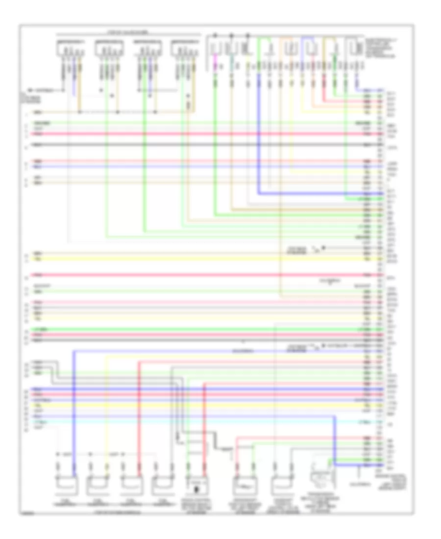
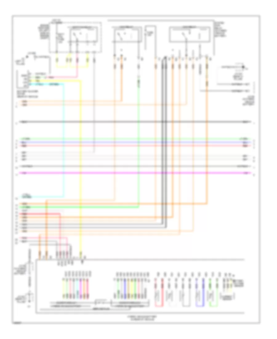
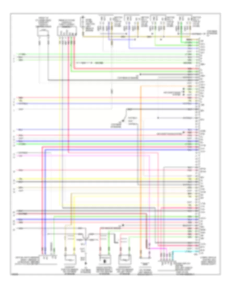
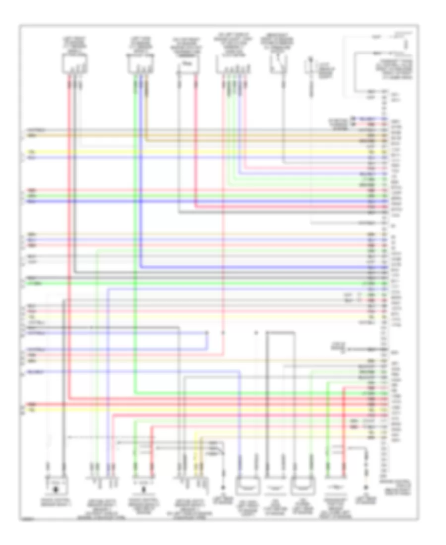
2.4L, Engine Controls Wiring Diagram (4 of 4) for Toyota Camry 2008
List of elements for 2.4L, Engine Controls Wiring Diagram (4 of 4) for Toyota Camry 2008:
- (top of intake manifold)
- (top of valve cover)
- (top rear of engine)
- A1a+
- A1a-
- C24
- C4 (top rear of engine)
- California
- Camshaft timing oil control valve (front of engine)
- Crankshaft position sensor (on left front of engine)
- Dsl
- E03
- E2g
- Eia
- Eknk
- Electronically controlled transmission solenoid (on transaxle)
- Engine control module (left side of engine compt)
- Eppm
- Eta
- Etha
- Etho
- Ethw
- Ex1b
- Fuel injector 1
- Fuel injector 2
- Fuel injector 3
- Fuel injector 4
- G2+
- G2-
- Ge01
- Gnd
- Ha1a
- Iaca
- Igf
- Igf1
- Ignition coil 1
- Ignition coil 2
- Ignition coil 3
- Ignition coil 4
- Igt1
- Igt2
- Igt3
- Igt4
- Knk1
- Knock control sensor (bank 1) (on top center of engine)
- Nc+
- Nc-
- Nca
- Ne+
- Ne-
- Nt+
- Nt-
- Oc1+
- Oc1-
- Ox1b
- Pnk
- Ppmp
- Red
- Sl1+
- Sl1-
- Sl2+
- Sl2-
- Sl3+
- Sl3-
- Slt+
- Slt-
- Tha
- Tho
- Tho1
- Thw
- Transmission revolution sensor (turbine) (near left rear of engine)
- Vcia
- Vcpp
- Vcta
- Vta1
- Vta2
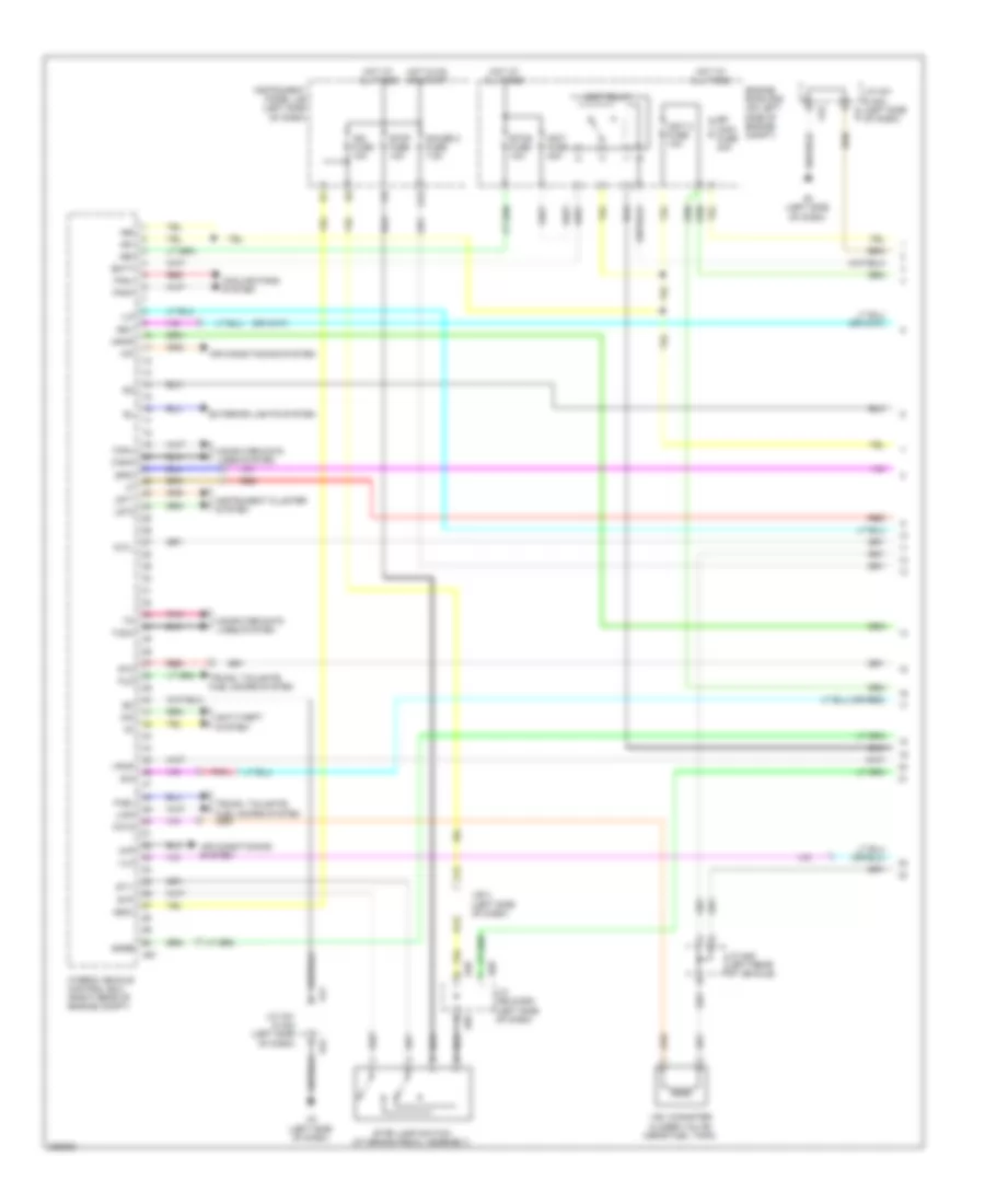
2.4L, Hybrid System Wiring Diagram (1 of 7) for Toyota Camry 2008
List of elements for 2.4L, Hybrid System Wiring Diagram (1 of 7) for Toyota Camry 2008:
- +b1
- +b2
- +bm
- A3 (left side of dash)
- A41
- A42
- A58
- A61
- Air conditioning system
- Anti-theft system
- Batt
- Canh
- Canl
- Ccv2
- Computer data lines system
- Cooling fans system
- E40
- Efi main fuse 30a
- Engine room r/b (on left side of engine compt)
- Etcs fuse 10a
- Exterior lights system
- F12
- Fanh
- Fanl
- Fctl
- Fuel
- Fuo
- G12
- Gauge 2 fuse 7.5a
- Hot at all times
- Hot in on or start
- Hybrid vehicle control ecu (right rear of engine compt)
- Igct 2 fuse 10a
- Igct fuse 30a
- Igct relay
- Ign fuse 10a
- Igsw
- Ilk
- Imi
- Imo
- Instrument cluster system
- Instrument panel j/b (left side of dash)
- Iwp
- J/b 3 (left side of dash)
- J/c a41 & a42 (left side of dash)
- J/c a58 & e40 (left side of dash)
- J/c n28 (left rear of vehicle)
- K12
- Lido
- Lst1
- Lst2
- Mpmp
- Pnk
- Rdy
- Red
- Sio
- Smrb
- Spdi
- St1-
- St2
- Stop fuse 10a
- Stop lamp switch (at brake pedal assembly)
- Stp
- Tach
- Trunk, tailgate, fuel doors system
- Vlo
- Vpmp
- Vsv (canister closed valve) (near fuel tank)
2.4L, Hybrid System Wiring Diagram (2 of 7) for Toyota Camry 2008
List of elements for 2.4L, Hybrid System Wiring Diagram (2 of 7) for Toyota Camry 2008:
- (left side of dash) main body ecu
- A1 (left front of engine compt)
- Am2
- Battery thermometer sensor (right rear of luggage compt)
- C/opn relay
- C6 (top rear of engine)
- Canh
- Canister pressure sensor
- Canister pump module (left rear of vehicle)
- Canl
- Computer data lines system
- Current breaker sensor (left front of engine compt)
- D12
- E1 (left side of dash)
- E10
- E11
- E12
- E13
- Efi relay
- Engine room j/b (on left side of engine compt)
- Fuel suction pump & gauge assembly (at fuel tank)
- Fuel tank pressure sensor
- G11
- Gauge
- Gnd
- Ig2d
- Inds
- Indw
- Instrument cluster system
- J/b 4 (center of dash)
- Leak detection pump
- N1 (left "c" pillar)
- Pnk
- Power switch
- Ptnk
- Pump
- Rdy
- Red
- Ss1
- Ss2
- Ssw1
- Ssw2
- Stsw
- Swil
- Vent valve
2.4L, Hybrid System Wiring Diagram (3 of 7) for Toyota Camry 2008
List of elements for 2.4L, Hybrid System Wiring Diagram (3 of 7) for Toyota Camry 2008:
- (left side of engine compt) inverter
- (or red)
- +b2
- A61
- A62
- Abfs
- As1
- As1g
- Bth+
- Bth-
- Ccs
- Clk+
- Clk-
- Cruise control system
- Drn1
- Drn2
- Drn3
- Drn4
- Drn5
- Drn8
- Eib
- Ep1
- Ep2
- Eppm
- Eptk
- Gmt
- Gmtg
- Gnd
- Gnd1
- Gnd2
- Hsdn
- Htm+
- Htm-
- Hybrid vehicle control ecu (right rear of engine compt)
- Ilk
- Ilki
- Ilko
- Inter lock switch (in hybrid vehicle battery)
- J/c a43 (left front of engine compt)
- J/c n6 (in hybrid vehicle battery)
- J/c o21 (rear "c" pillar)
- Mmt
- Mmtg
- Mrel
- Mth+
- Mth-
- Nodd
- Pnk
- Ppmp
- Ptnk
- Red
- Req+
- Req-
- Smrg
- Smrp
- Thb
- Vcp1
- Vcp2
- Vcpp
- Vcpt
- Vpa
- Vpa2
2.4L, Hybrid System Wiring Diagram (4 of 7) for Toyota Camry 2008
List of elements for 2.4L, Hybrid System Wiring Diagram (4 of 7) for Toyota Camry 2008:
- (left front of engine compt) motor generator 1
- (left side of engine compt) inverter
- (or red)
- (top rear of engine) c6
- A41
- A42
- Accelerator position sensor (on accelerator pedal assembly)
- Acpb
- Acpe
- Air conditioning system
- Amd
- C58
- C59
- C60
- C61
- Cbi
- Cei
- Converter (in hybrid vehicle battery)
- Dc/dc fuse 120a
- Drn6
- Engine room j/b (on left side of engine compt)
- Ep1
- Ep2
- Gcs
- Gcsg
- Gmt
- Gmtg
- Gnd
- Grf
- Grfg
- Gsn
- Gsng
- Hot at all times
- Idh
- Igct
- In+
- In-
- J/c a41 & a42 (left side of dash)
- J/c n6 (in hybrid vehicle battery)
- Mcs
- Mcsg
- Mmt
- Mmtg
- Motor generator 2 (left side of engine compt)
- Mrf
- Mrfg
- Msn
- Msng
- Nca
- Nodd
- Pnk
- Prec
- Red
- Smrp
- Vcp1
- Vcp2
- Vlo
- Vpa1
- Vpa2
2.4L, Hybrid System Wiring Diagram (5 of 7) for Toyota Camry 2008
List of elements for 2.4L, Hybrid System Wiring Diagram (5 of 7) for Toyota Camry 2008:
- (or red)
- Batt fan fuse 10a
- Batt fan relay
- Battery blower motor (rear of vehicle)
- Battery voltage sensor
- Bth+
- Bth-
- Busbar module 1
- Busbar module 2
- Current sensor
- Engine room r/b (on left side of engine compt)
- Fuse 15a
- Gb0
- Gb0 r3
- Gb1
- Gb2
- Gb3
- Gc0
- Gib
- Gnd
- Gnd0
- Hot at all times
- Hybrid vehicle battery
- Hybrid vehicle battery (in rear of vehicle)
- Idh
- Ig0
- Igc1
- J/c n29
- J/c n6 (in hybrid vehicle battery)
- J/c o21 (rear "c" pillar)
- Main relay
- N1 (left "c" pillar)
- Nca
- Pnk
- Red
- Service plug
- Si0
- System main relay (in hybrid vehicle battery)
- Tb0
- Tb1
- Tb2
- Tb3
- Tc0
- Vb1
- Vb10
- Vb11
- Vb12
- Vb13
- Vb14
- Vb15
- Vb16
- Vb17
- Vb2
- Vb3
- Vb4
- Vb5
- Vb6
- Vb7
- Vb8
- Vb9
- Vib
- Vim
- Vm0
2.4L, Hybrid System Wiring Diagram (6 of 7) for Toyota Camry 2008
List of elements for 2.4L, Hybrid System Wiring Diagram (6 of 7) for Toyota Camry 2008:
- (on transaxle) park/neutral position switch
- (top rear of engine) c6
- A1 (left front of engine compt)
- A41
- A42
- Am2 fuse 7.5a
- Anti-lock brakes system
- B10
- Buzzer
- Can i/f
- Combination meter
- Computer data lines system
- D10
- Drive ic
- E10
- E12
- Efi 3 fuse 10a
- Engine coolant temperature sensor (on top rear of engine)
- Engine oil pressure switch (rear of engine)
- Engine room r/b (on left side of engine compt)
- Fuel expenses gauge
- Fuel injectors (top of intake manifold)
- Heated oxygen sensor (bank 1 sensor 2) (in exhaust)
- Hot at all times
- Ig2
- Ig2 fuse 20a
- Ig2 relay
- J/b 3 (left side of dash)
- J/b 4 (center of dash)
- J/b a41 & a42 (left side of dash)
- M10
- M12
- Malfunction ind lamp
- Micro computer
- Multi lcd
- Nca
- Pnk
- Red
- Temperature gauge
2.4L, Hybrid System Wiring Diagram (7 of 7) for Toyota Camry 2008
List of elements for 2.4L, Hybrid System Wiring Diagram (7 of 7) for Toyota Camry 2008:
- (front of cylinder head) camshaft timing oil control valve
- (rear of intake manifold) throttle body assembly
- (top rear of engine) c4
- +bs
- A1a+
- A1a-
- Af+
- Af-
- Air conditioning system
- Air fuel ratio sensor (bank 1 sensor 1) (in exhaust, before catalytic converter)
- C4 (top rear of engine)
- C6 (top rear of engine)
- C64
- Camshaft position sensor (on top rear of engine)
- Clk
- Crankshaft position sensor (on left front of engine)
- E01
- E02
- E03
- E04
- E12
- E2g
- Eknk
- Eta
- Etha
- Ethw
- Eti
- Evg
- G2+
- G2-
- Ge01
- Gnd
- Ha1a
- Ht1b
- Hybrid vehicle control ecu (right rear of engine compt)
- Igf
- Ignition coil 1 (top of valve cover)
- Ignition coil 2 (top of valve cover)
- Ignition coil 3 (top of valve cover)
- Ignition coil 4 (top of valve cover)
- Igt1
- Igt2
- Igt3
- Igt4
- Ite
- Knk1
- Knock control sensor (bank 1) (on top center of engine)
- Mass airflow meter (on left side of engine compt, part of air intake assembly)
- Me01
- Mops
- Nca
- Ne+
- Ne-
- Noise filter (ignition) (left rear of engine)
- O1b-
- Oc1+
- Oc1-
- Ox1b
- Pnk
- Prg
- Red
- Stb
- Tha
- Thw
- Vcta
- Vsv (purge) (left rear of engine compt)
- Vta
- Vta2
3.5L
3.5L, Engine Performance Wiring Diagram (1 of 5) for Toyota Camry 2008
List of elements for 3.5L, Engine Performance Wiring Diagram (1 of 5) for Toyota Camry 2008:
- (behind right side of dash) engine control module
- (left "c" pillar) n1
- (left side of dash) a3
- +b2
- +bm
- A/f fuse 20a
- A/f relay
- A41
- A42
- A55
- A56
- Accelerator position sensor (on accelerator pedal assembly)
- Accr
- Aciv
- Anti-theft system
- B10
- Batt
- C/opn relay
- Canh
- Canl
- Ccs
- Computer data lines system
- Cooling fans system
- Cruise control system
- D12
- E10
- E11
- E12
- E13
- Efi 1 fuse 10a
- Efi 2 fuse 15a
- Efi 3 fuse 10a
- Efi main fuse 30a
- Efi relay
- Engine room j/b (on left side of engine compt)
- Engine room r/b (on left side of engine compt)
- Epa
- Epa2
- Etcs fuse 10a
- Fuel suction pump & gauge assembly (at fuel tank)
- Gauge
- Hot at all times
- Ig2d
- Igsw
- Imi
- Imo
- Instrument cluster system
- J/b 3 (left side of dash)
- J/b 4 (center of dash)
- J/c 41 & 42 (left side of dash)
- J/c 41 (right side of dash)
- M10
- Main body ecu (w/ smart key system) (left side of dash)
- Mpmp
- Mrel
- Pnk
- Pump
- Red
- Rfc
- Sftd
- Sftu
- Short connector 56 & 57 (right side a57 of dash)
- Spd
- St1-
- Sta
- Starting/charging system
- Stp
- Stsw
- Tach
- Vcp2
- Vcpa
- Vpa
- Vpa2
- Vpmp
- Vsv (air intake control) (left of engine compt, in air intake)
3.5L, Engine Performance Wiring Diagram (2 of 5) for Toyota Camry 2008
List of elements for 3.5L, Engine Performance Wiring Diagram (2 of 5) for Toyota Camry 2008:
- (center of dash) j/c e48
- (left side of dash) j/b 3
- (left side of dash) j/c 41 & 42
- (rear of engine compt) j/c 57
- (top of valve cover)
- A11
- A41
- A42
- A58
- Anti-lock brakes system
- C12
- C7 (center rear of engine compt)
- Camshaft timing oil control valve (left intake side) (front of left cylinder head)
- Can i/f
- Combination meter
- Computer data lines system
- D10
- Drive ic
- E40
- F1 (left side of dash)
- F12
- Gnd
- H10
- Hot at all times
- Hot in on or start
- Ig2
- Igf
- Ign fuse 10a
- Ignition coil 1
- Ignition coil 2
- Ignition coil 3
- Ignition coil 4
- Ignition coil 5
- Ignition coil 6
- Igt1
- Igt2
- Igt3
- Igt4
- Igt5
- Igt6
- Ill+
- Ill-
- Instrument panel j/b (left side of dash)
- Interior lights system
- J/b 4 (center of dash)
- J/c 40 & 58 (left side of dash)
- J/c 41 & (left side a41 of dash)
- K12
- Malfunction ind lamp
- Micro computer
- Multi lcd
- Noise filter (left ignition) (at top of engine)
- Noise filter (right ignition) (rear of engine compt)
- Pnk
- Red
- Sftd
- Sftu
- Speedo- meter
- Stop fuse 10a
- Stop lamp switch
- Tacho- meter
- Transmission control switch
3.5L, Engine Performance Wiring Diagram (3 of 5) for Toyota Camry 2008
List of elements for 3.5L, Engine Performance Wiring Diagram (3 of 5) for Toyota Camry 2008:
- (left rear of vehicle) canister pump module
- (top of engine)
- (top of engine) c4
- A2 (behind left front headlamp)
- Acc
- Acm
- C55
- Can+
- Can-
- Canister pressure sensor
- Computer data lines system
- Ecu ig 2 fuse 7.5a
- Engine control module (behind right side of dash)
- Engine room r/b (on left side of engine compt)
- Eo1
- Eo2
- Eo4
- Eo5
- F19
- G12
- Gauge 2 fuse 7.5a
- Geo1
- Hot at all times
- Hot in on or start
- Ht1b
- Ht2b
- Ig2 fuse 20a
- Ig2 relay
- Ignition switch
- Igt1
- Igt2
- Igt3
- Igt4
- Igt5
- Igt6
- Instrument panel j/b (left side of dash)
- J/b 3 (left side of dash)
- J/c 43 (behind left front headlamp)
- J/c 57 (rear of engine compt)
- Leak detection pump
- Lock
- Meo1
- Nca
- Oc2+
- Oc2-
- Oe1+
- Oe1-
- Oe2+
- Oe2-
- Off
- Pnk
- Red
- Run
- Start
- Throttle body assembly (top rear of engine)
- Vent valve
- Vta
- Vta2
- W/ smart key system
- W/o smart key system
3.5L, Engine Performance Wiring Diagram (4 of 5) for Toyota Camry 2008
List of elements for 3.5L, Engine Performance Wiring Diagram (4 of 5) for Toyota Camry 2008:
- (rear of engine) vvt sensor (bank 1 exhaust side)
- (top front of engine) vvt sender (bank 1 intake side)
- (top of intake manifold) fuel injectors
- C5 (left rear of engine)
- Camshaft timing oil control valve (left exhaust side) (front of left cylinder head)
- Camshaft timing oil control valve (right exhaust side) (front of right cylinder head)
- Ex+
- Ex-
- Gauge 1 fuse 10a
- H16
- Heated oxygen sensor (bank 1 sensor 2) (in left exhaust, after catalytic converter)
- Heated oxygen sensor (bank 2 sensor 2) (on left exhaust manifold)
- Hot in on or start
- Ht1b
- Ht2b
- Instrument panel j/b (left side of dash)
- Nca
- Ox1b
- Ox2b
- Park/neutral position switch (on transaxle)
- Pnk
- Red
- Transmission control ecu (left front of engine compt)
- Vc2
- Vvr+
- Vvr-
3.5L, Engine Performance Wiring Diagram (5 of 5) for Toyota Camry 2008
List of elements for 3.5L, Engine Performance Wiring Diagram (5 of 5) for Toyota Camry 2008:
- (left front of engine) vvt sensor (bank 2 intake side)
- (left side of engine) vvt sensor (bank 2 exhaust side)
- (near right front of engine) power steering oil pressure switch
- (on left side of engine compt, part of air intake assembly) mass air flow meter
- (on top front of engine) engine coolant temperature sensor
- (top of engine) c4
- A1a+
- A1a-
- A2a+
- A2a-
- Acis
- Air fuel ratio sensor (bank 1 sensor 1) (on right side of engine, in exhaust pipe)
- Air fuel ratio sensor (bank 2 sensor 1) (on left side of engine, in exhaust pipe)
- C5 (left rear of engine)
- C55
- Camshaft timing oil control valve (right intake side) (front of right cylinder head)
- Crankshaft position sensor (on lower left front of engine)
- E2g
- Ekn2
- Eknk
- Engine control module (behind right side of dash)
- Eo3
- Eppm
- Eta
- Etha
- Ethw
- Ev1+
- Ev1-
- Ev2+
- Ev2-
- Ex+
- Ex-
- Ex1b
- Ex2b
- Ha1a
- Ha2a
- Igf1
- J/c 57 (rear of engine compt)
- Knk1
- Knk2
- Knock control sensor (bank 1)
- Knock control sensor (bank 2) (center of engine)
- Nca
- Ne+
- Ne-
- Nsw
- Oc1+
- Oc1-
- Ox1b
- Ox2b
- Pnk
- Ppmp
- Prg
- Psw
- Red
- Star
- Starting/ charging system
- Tha
- Thw
- Vc2
- Vce1
- Vce2
- Vcpp
- Vcta
- Vcv1
- Vcv2
- Vsv (acis) (top center of engine)
- Vsv (acm) (left front of engine compt)
- Vsv (purge) (left rear of engine)
- Vta1
- Vta2
- Vv1+
- Vv1-
- Vv2+
- Vv2-
- Vvl+
- Vvl-