ENGINE PERFORMANCE
2.2L
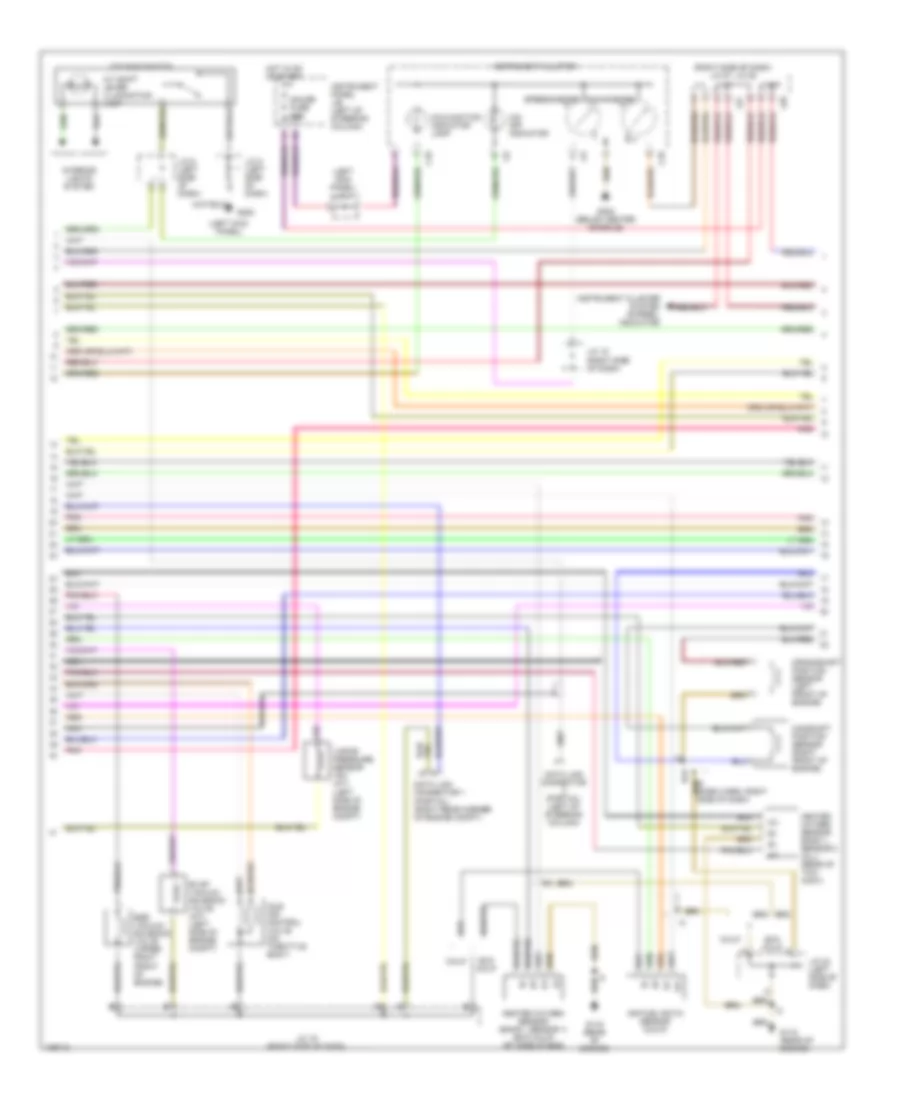
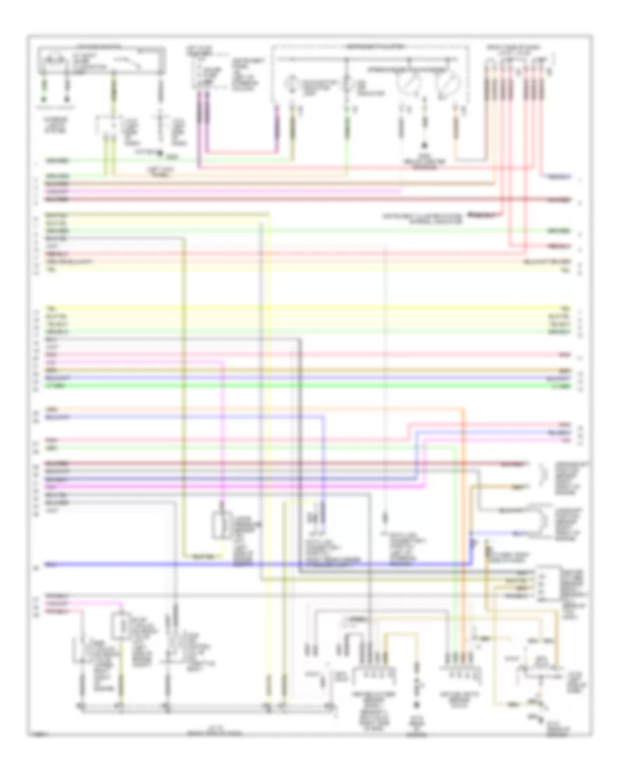
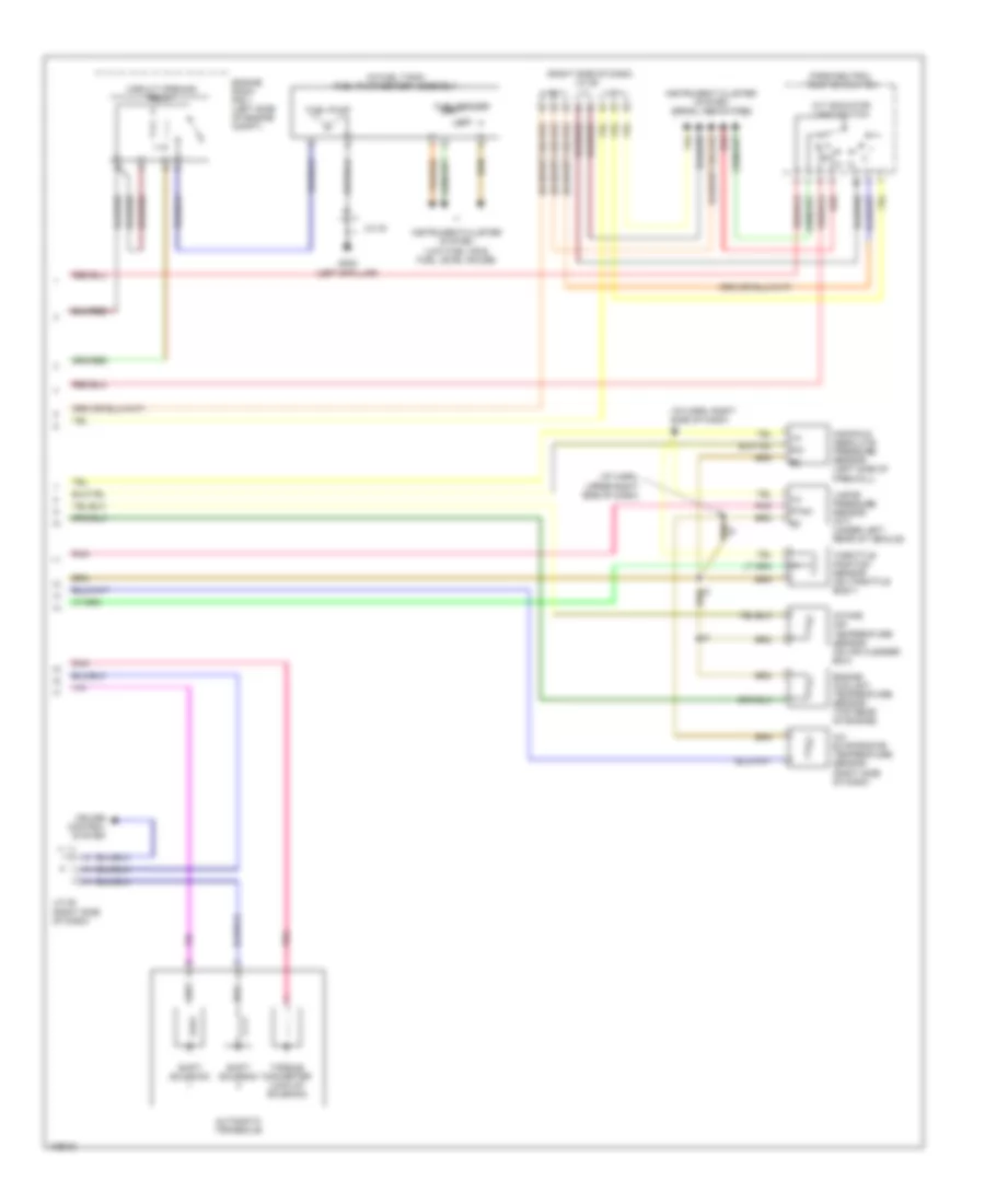
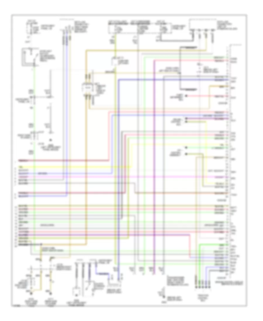
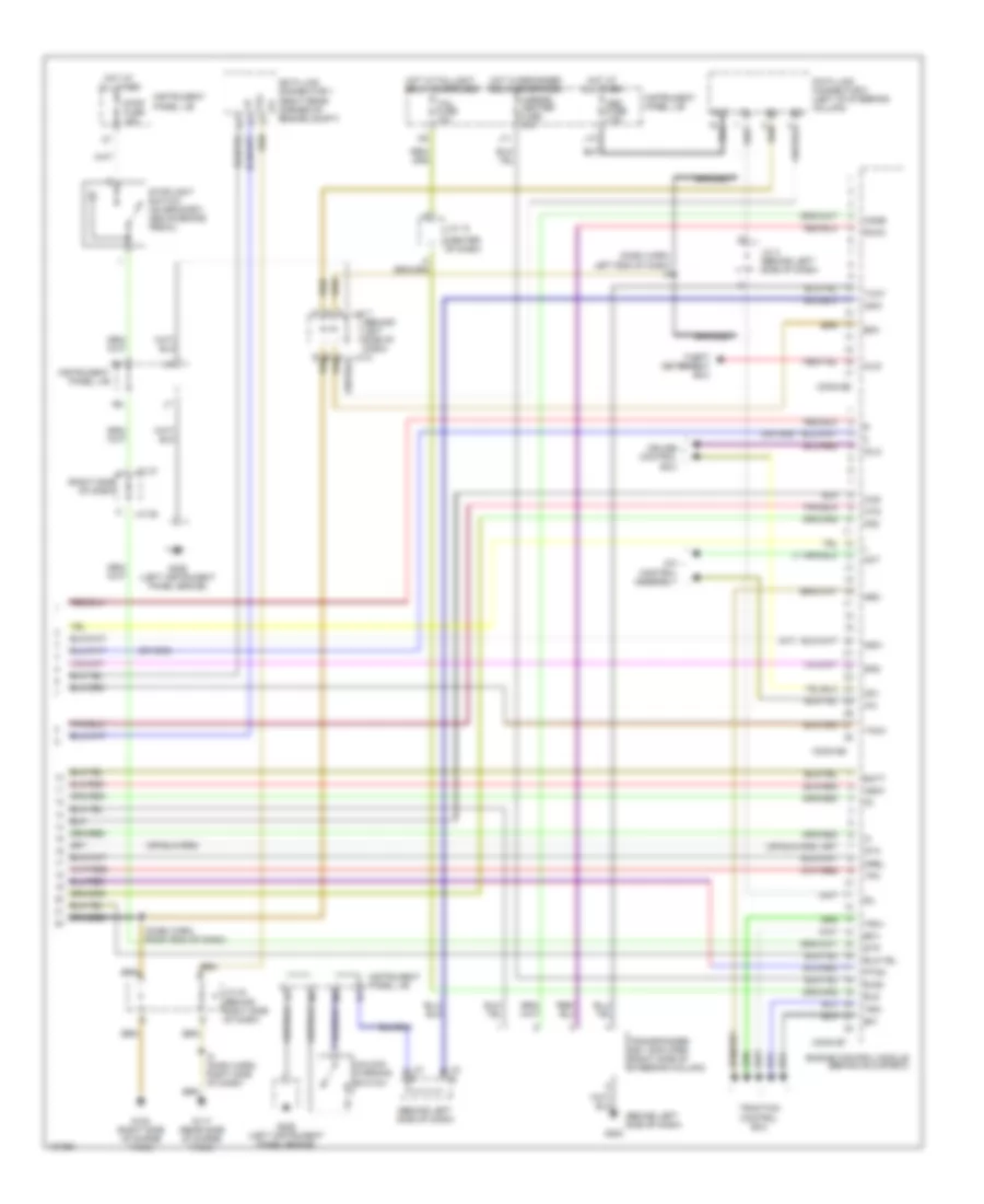
2.2L, Engine Performance Wiring Diagrams, with Immobilizer (1 of 3) for Toyota Camry XLE 1998

List of elements for 2.2L, Engine Performance Wiring Diagrams, with Immobilizer (1 of 3) for Toyota Camry XLE 1998:
- (a/t)
- (behind left headlamp) g106
- (calif)
- (dash harn, left end of dash)
- (dash harn, right end of dash)
- (eng harn, left front fender)
- (exc calif)
- (left side of engine)
- (right side of dash)
- (right side of dash) j/c 27, j/c 28
- A j27
- A/c sw
- A/c system
- Acc
- Af+
- Af-
- Am2
- B j27
- Batt
- C j28
- C10
- Conn e7
- Conn e8
- Conn e9
- Cruise control system
- Defogger system
- E01
- E02
- E03
- E04
- Efi fuse 15a
- Efi relay
- Egr
- Els
- Engine control module (behind glove box)
- Engine room r/b 2 (left side of engine compt)
- Evp
- Exterior lights system
- Fuel injector
- G115 (rear of engine)
- Gnd
- Hot at all times
- Ht1
- Ht2
- Htaf
- I2 (dash harn, behind glove blox)
- Idle-up diode (right side of dash taped to harn)
- Idlo
- Ig2
- Igf
- Ign fuse 5a
- Ignition coil/ igniter 1
- Ignition coil/ igniter 2
- Ignition switch
- Igsw
- Igt
- Igt1
- Igt2
- Instrument panel j/b (left of steering column)
- Iscc
- Isco
- J/c 19 (right side of dash)
- J/c 21
- J/c 23 (right side of dash)
- J/c 25 (right side of dash)
- J/c 7
- J/c 7, j/c 8 (left side of dash)
- J/c 8
- Knk
- Lock
- Lock in
- Mgc
- Nsw
- Od1
- Od2
- Ox1
- Ox2
- Pim
- Pnk
- Power steering oil pressure switch (right rear of engine)
- Prs
- Ps sw
- Ptnk
- Red
- Sil
- Spd
- Sta
- Start
- Starting/ charging system
- Stop fuse 15a
- Stop light switch (on bracket above brake pedal)
- Stp
- Tach
- Te1
- Tha
- Thr
- Thw
- Tpc
- Vta
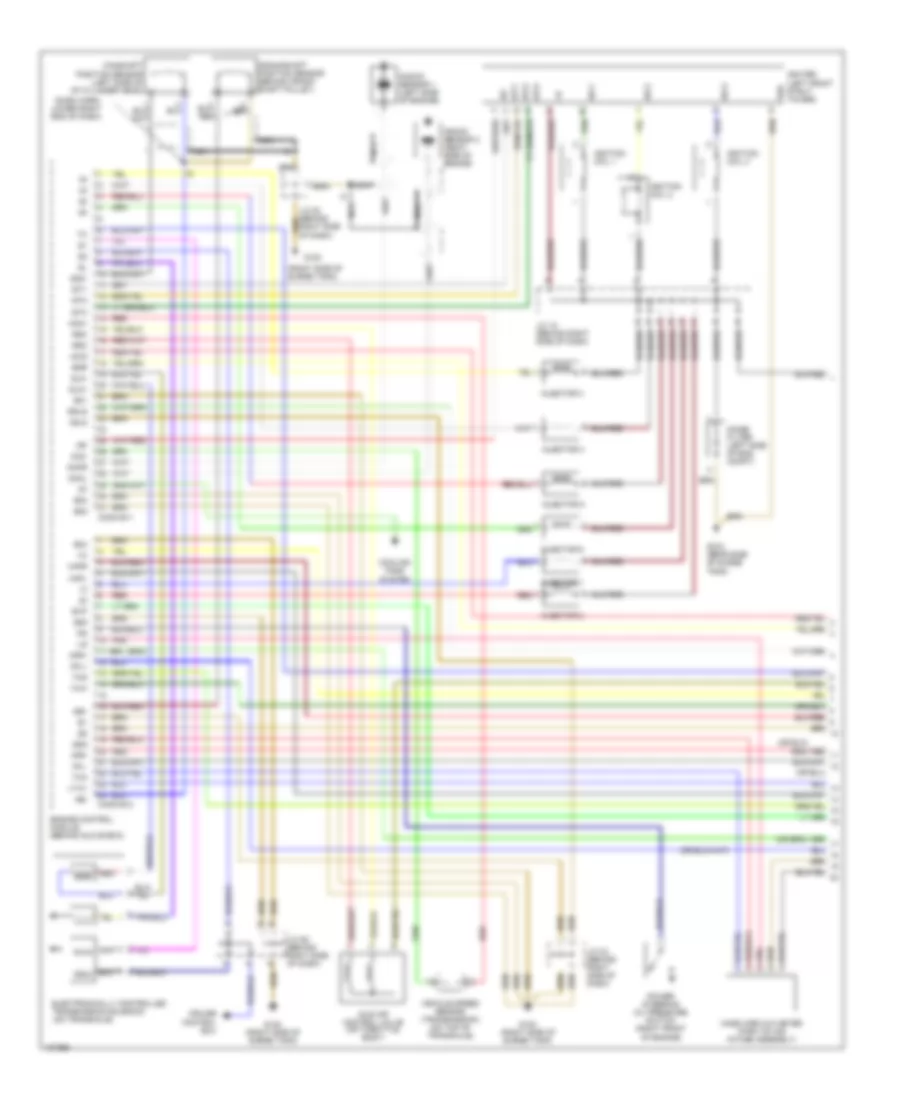
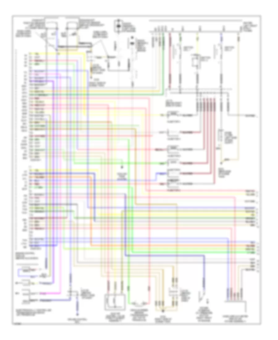
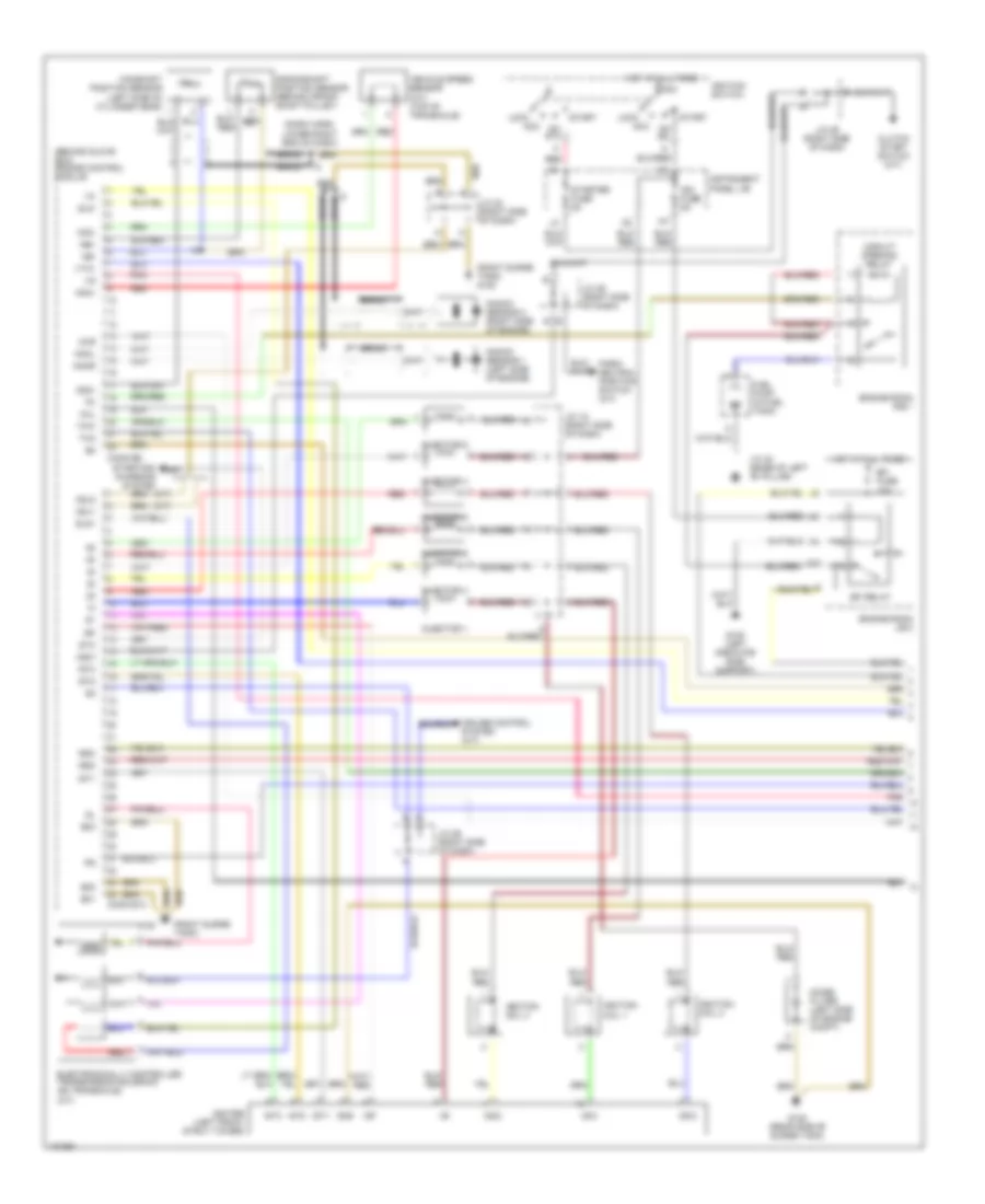
2.2L, Engine Performance Wiring Diagrams, with Immobilizer (2 of 3) for Toyota Camry XLE 1998
List of elements for 2.2L, Engine Performance Wiring Diagrams, with Immobilizer (2 of 3) for Toyota Camry XLE 1998:
- (left kick panel)
- (left kick panel) j/c 4
- (left side of engine compt)
- (right side of dash) j/c 27, j/c 28
- A/t shift lever illumination lamp
- Af+
- Af-
- Air fuel ratio sensor (calif)
- C j27
- C10
- Calif
- Camshaft position sensor (right front of engine)
- Crankshaft position sensor (left front of engine)
- Data link connector (partial) (left of steering column)
- Data link connector 1 (partial) (right rear corner of engine compt)
- Egr vacuum solenoid valve (upper right front of engine)
- Evap vacuum solenoid valve (a/t) (left side of engine compt)
- Exc calif
- F j28
- G115 (rear of engine)
- G200
- G302 (below center console)
- Gauge fuse 10a
- Heated oxygen sensor (bank1, sensor 1) (exc calif) (rt side of eng)
- Heated oxygen sensor bank 1, sensor 2 (all) (rear of twc conv)
- Hot in on or start
- Idle air control valve (on throttle body)
- Instrument cluster
- Instrument cluster system (r-prndl indicator)
- Instrument panel j/b (left of steering column)
- Interior lights system
- J/c 15 (right side of dash)
- J/c 19 (right side of dash)
- J/c 23 (left side of dash)
- J/c 5 (left side of dash)
- J/c 6 (left side of dash)
- Malfunction indicator lamp
- Nca
- O/d main switch
- O/d off indicator
- Pnk
- Speedometer
- Tachometer
- Vapor pressure sensor vsv (a/t)
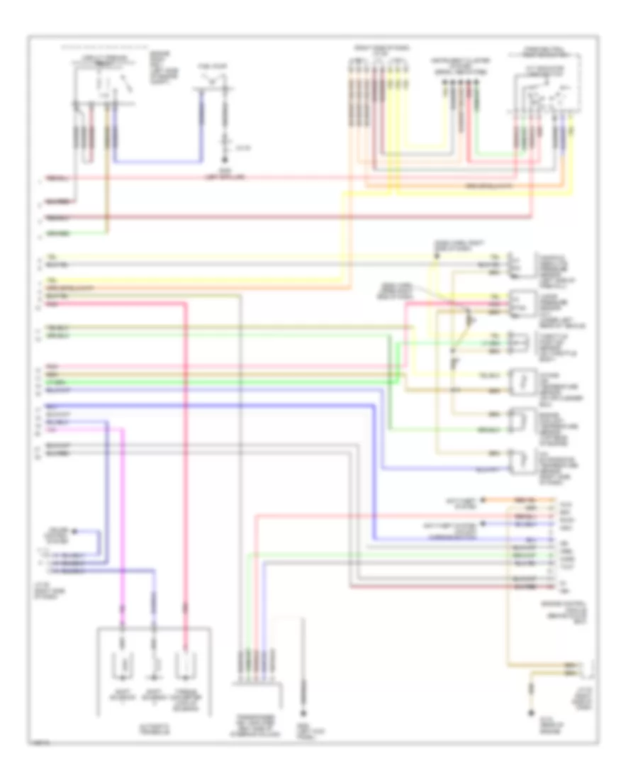
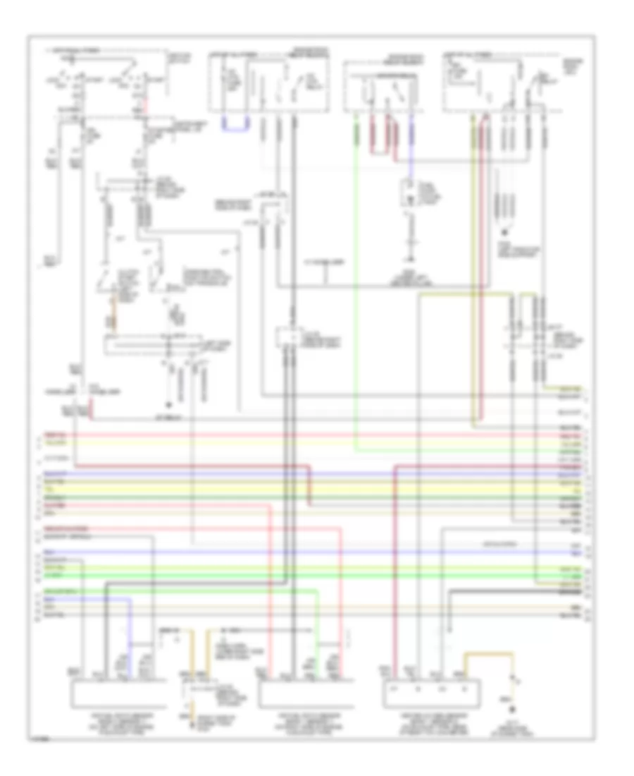
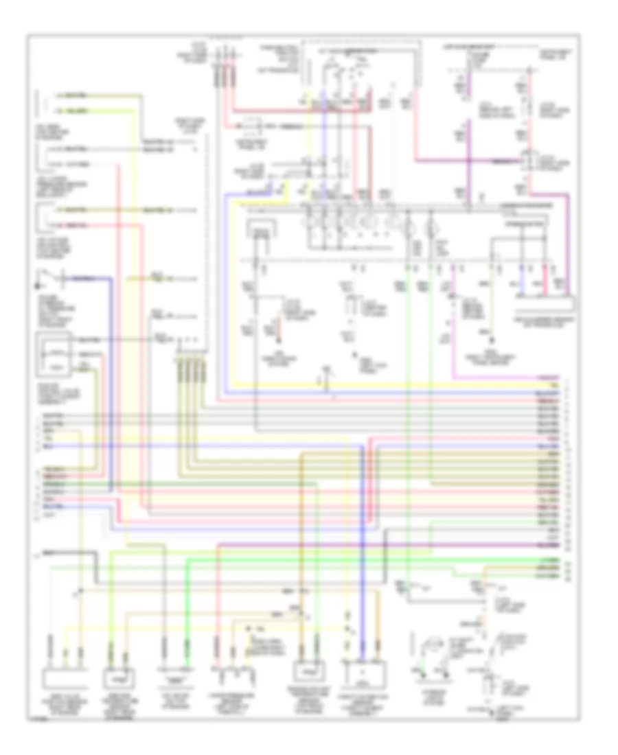
2.2L, Engine Performance Wiring Diagrams, with Immobilizer (3 of 3) for Toyota Camry XLE 1998
List of elements for 2.2L, Engine Performance Wiring Diagrams, with Immobilizer (3 of 3) for Toyota Camry XLE 1998:
- (dash harn, right side of dash) i2
- (dash harn, upper right side of dash)
- (right side of dash) j/c 29
- A/c evaporator temperature sensor (right side of dash)
- A/t indicator light switch
- Anti-theft system
- Anti-theft system (unlock warning switch)
- Automatic transaxle
- Circuit opening relay
- Code
- Cruise control system
- E0m
- Engine control module (behind glove box)
- Engine coolant temperature sensor (top rear of engine)
- Engine room r/b 1 (left side of engine compt)
- Fuel pump
- G115 (rear of engine)
- G200 (left kick panel)
- G308 (left b-pillar)
- Imld
- Instrument cluster system (prndl indicators)
- Intake air temperature sensor (on air cleaner box)
- J/c 23 (right side of dash)
- J/c 25 (right side of dash)
- J/c 40
- Ksw
- Manifold absolute pressure sensor (left side of firewall)
- Mrel
- Ne+
- Ne-
- Park/neutral position switch
- Pim
- Pnk
- Ptnk
- Red
- Rxck
- Shift solenoid
- Throttle position sensor (on throttle body)
- Torque converter lock-up solenoid
- Transponder key amplifier (rigt side of steering column)
- Txct
- Vapor pressure sensor (a/t) (under left rear of vehicle)
2.2L, Engine Performance Wiring Diagrams, without Immobilizer (1 of 3) for Toyota Camry XLE 1998
List of elements for 2.2L, Engine Performance Wiring Diagrams, without Immobilizer (1 of 3) for Toyota Camry XLE 1998:
- (a/t)
- (behind left headlamp) g106
- (calif)
- (eng harn, left front fender)
- (exc calif)
- (left side of dash)
- (rear of engine)
- (right side of dash)
- (right side of dash) j/c 27, j/c 28
- A j27
- A/c sw
- A/c system
- Acc
- Af+/ox1
- Af-
- Am2
- B j27
- Batt
- C j28
- C10
- Conn e7
- Conn e8
- Conn e9
- Cruise control system
- Defogger system
- E01
- E02
- E03
- E04
- Efi fuse 15a
- Efi relay
- Egr
- Els
- Engine control module (behind glove box)
- Engine room r/b 2 (left side of engine compt)
- Evp
- Exterior lights system
- Fuel injector
- G115 (rear of engine)
- Gnd
- Hot at all times
- Ht1
- Ht2
- Htaf
- I2 (i/p harn, behind glove blox)
- Idle-up diode (right side of dash taped to harn)
- Idlo
- Ig2
- Igf
- Ign fuse 5a
- Ignition coil/ igniter 1
- Ignition coil/ igniter 2
- Ignition switch
- Igt
- Igt1
- Igt2
- Instrument panel j/b (left of steering column)
- Iscc
- Isco
- J/c 1
- J/c 15 (top center of dash)
- J/c 19 (right side of dash)
- J/c 21
- J/c 23 (right side of dash)
- J/c 25 (right side of dash)
- J/c 7, j/c 8
- Knk
- Knock sensor (left of engine block)
- Lock
- Lock in
- Mgc
- Ne+
- Ne-
- Nsw
- Od1
- Od2
- Ox2
- Pim
- Pnk
- Power steering oil pressure switch (right front of engine)
- Prs
- Ps sw
- Ptnk
- Red
- Sil
- Spd
- Sta
- Start
- Starting/ charging system
- Starting/charging system
- Stop fuse 15a
- Stop light switch
- Stp
- Tach
- Te1
- Tha
- Thr
- Thw
- Tpc
- Vta
2.2L, Engine Performance Wiring Diagrams, without Immobilizer (2 of 3) for Toyota Camry XLE 1998
List of elements for 2.2L, Engine Performance Wiring Diagrams, without Immobilizer (2 of 3) for Toyota Camry XLE 1998:
- (left kick panel)
- (left side of engine compt)
- (right side of dash) j/c 27, j/c 28
- A/t shift lever illumination lamp
- Af+
- Af-
- Air fuel ratio sensor (calif)
- C j27
- C10
- Calif
- Camshaft position sensor (right front of engine)
- Crankshaft position sensor (right front of engine)
- Data link connector 1 (partial) (right rear corner of engine compt)
- Data link connector 3 (partial) (left of steering column)
- Egr vacuum solenoid valve (upper right front of engine)
- Evap vacuum solenoid valve (a/t) (left side of engine compt)
- Exc calif
- F j28
- G115 (rear of engine)
- G200
- G302 (below center console)
- Gauge fuse 10a
- Heated oxygen sensor (bank 1 sensor 1) (exc calif) (right side of eng)
- Heated oxygen sensor bank 1 sensor 2 (all) (rear of twc conv)
- Hot in on or start
- Idle air control valve (on throttle body)
- Instrument cluster
- Instrument cluster system (r-prndl indicator)
- Instrument panel j/b (left of steering column)
- Interior lights system
- J/c 19 (right side of dash)
- J/c 23 (left side of dash)
- J/c 5 (left side of dash)
- J/c 6 (left side of dash)
- Malfunction indicator lamp
- O/d main switch
- O/d off indicator
- Pnk
- Speedometer
- Tachometer
- Vapor pressure sensor vsv (a/t)
2.2L, Engine Performance Wiring Diagrams, without Immobilizer (3 of 3) for Toyota Camry XLE 1998
List of elements for 2.2L, Engine Performance Wiring Diagrams, without Immobilizer (3 of 3) for Toyota Camry XLE 1998:
- (i/p harn, right side of dash) i2
- (i/p harn, upper right side of dash)
- (in fuel tank) fuel pump/sender assembly
- (right side of dash) j/c 29
- A/c evaporator temperature sensor (right side of dash)
- A/t indicator light switch
- Automatic transaxle
- Circuit opening relay
- Cruise control system
- Engine coolant temperature sensor (top rear of engine)
- Engine room r/b 1 (left side of engine compt)
- Fuel pump
- Fuel sender
- G308 (left b-pillar)
- Instrument cluster system (low fuel ind & fuel level gauge)
- Instrument cluster system (prndl indicators)
- Intake air temperature sensor (on air cleaner box)
- J/c 25 (right side of dash)
- J/c 40
- Manifold absolute pressure sensor (left side of firewall)
- Park/neutral position switch
- Pim
- Pnk
- Ptnk
- Red
- Shift solenoid
- Throttle position sensor (on throttle body)
- Torque converter lock-up solenoid
- Vapor pressure sensor (a/t) (under left rear of vehicle)
3.0L
3.0L, Engine Performance Wiring Diagrams, California (1 of 4) for Toyota Camry XLE 1998
List of elements for 3.0L, Engine Performance Wiring Diagrams, California (1 of 4) for Toyota Camry XLE 1998:
- (dash harn, lower right end of dash)
- (right side of surge tank)
- Acis
- Adj2
- Afl+
- Afl-
- Afr+
- Afr-
- Camshaft position sensor (left side of of cylinder head)
- Conn e10
- Conn e11
- Cooling fans system
- Crankshaft position sensor (behind crank- shaft pulley)
- Cruise control ecu
- E01
- E02
- E03
- E04
- E05
- E2g
- Egls
- Egr
- Electronically controlled transmission solenoid (on transaxle)
- Engine control module (behind glove box)
- Evp
- G120
- G120 (rear side of surge tank)
- G120 (right side of surge tank)
- G22+
- Grd
- Hafl
- Hafr
- Idle air control valve (on throttle body)
- Igc1
- Igc2
- Igc3
- Igf
- Igniter (left front strut tower)
- Ignition coil 1
- Ignition coil 2
- Ignition coil 3
- Igt1
- Igt2
- Igt3
- Injector 1
- Injector 2
- Injector 3
- Injector 4
- Injector 5
- Injector 6
- J/c 18 (behind right side of dash)
- J/c 24 (behind right side of dash)
- J/c 26 (behind right side of dash)
- Knkl
- Knkr
- Knock sensor 1 (left side of engine)
- Knock sensor 2 (right side of engine)
- Mass airflow meter (part of air intake assembly)
- Nc2+
- Nc2-
- Nca
- Ne+
- Ne-
- Noise filter (left side of eng compt)
- Pnk
- Power steering oil pressure switch (right front of engine)
- Red
- Rsc
- Rso
- Sln+
- Sln-
- Tha
- Thg
- Thw
- Vehicle speed sensor (transmission) (on top of transaxle)
- Vta1
3.0L, Engine Performance Wiring Diagrams, California (2 of 4) for Toyota Camry XLE 1998
List of elements for 3.0L, Engine Performance Wiring Diagrams, California (2 of 4) for Toyota Camry XLE 1998:
- (behind right side of dash)
- (dash harn, lower right side end of dash)
- (left side of dash)
- (or
- (right side of surge tank) g120
- (under left center pillar)
- A/f htr fuse 25a
- A/f htr relay
- A/t
- Acc
- Air fuel ratio sensor (bank 1 sensor 1) (on right side of engine, in exhaust pipe)
- Air fuel ratio sensor (bank 2 sensor 1) (on left side of engine, in exhaust pipe)
- Am2
- B j/c 28
- C10
- Cir opn relay
- Clutch start switch (left side of dash)
- Efi fuse 15a
- Efi relay
- Engine room j/b 2
- Engine room relay block 1
- Engine room relay block 2
- Fuel pump (in fuel tank)
- G108 (left radiator side support)
- G117 (rear side of surge tank)
- G308
- Heated oxygen sensor (bank 1 sensor 2) (on exhaust pipe, rear of rear twc converter)
- Hot at all times
- Ig2
- Ign fuse 5a
- Ignition switch
- Instrument panel j/b
- J/c 22 (behind right side of dash)
- J/c 25 (behind right side of dash)
- J/c 29 (behind right side of dash)
- J/c 36
- J/c 7
- J/c 8
- Lock
- M/t
- Nca
- P/n
- Park/neutral position switch (on transaxle)
- Red
- St relay
- St2
- Start
- Starter fuse 5a
- W/ immobiliser
- W/o immobiliser
3.0L, Engine Performance Wiring Diagrams, California (3 of 4) for Toyota Camry XLE 1998
List of elements for 3.0L, Engine Performance Wiring Diagrams, California (3 of 4) for Toyota Camry XLE 1998:
- (behind right side of dash)
- (dash harn, lower right end of dash)
- (left kick panel) g200
- A/c control assembly
- A/t indicator light switch (integral to park/ neutral position switch) (on transaxle)
- Braided
- C10
- Combination meter
- Egr gas temperature sensor (right rear of engine)
- Egr valve position sensor (right rear of engine)
- Engine coolant temperature sensor (top front of engine)
- G200 (left kick panel)
- G206 (right instrument panel brace)
- Gauge fuse 10a
- H10
- Hot in on or start
- Ig+
- Instrument panel j/b
- J/c 15 (right side of dash)
- J/c 20 (behind right side of dash)
- J/c 24 (behind right side of dash)
- J/c 27
- J/c 28
- J/c 28 a
- J/c 29 (behind right side of dash)
- J/c 4 (behind left side of dash)
- J/c 5 (behind left side of dash)
- J/c 5 (left side of dash)
- J/c 6 (behind left side of dash)
- Malf ind lamp
- O/d main switch
- O/d off ind
- Pnk
- Ptnk
- Red
- Speedometer
- Tacho- meter
- Throttle position sensor (on throttle body)
- Vapor pressure sensor (left side of firewall)
- Vehicle speed sensor (combination meter) (on transaxle)
- Vss
- Vsv (egr) (top center of engine)
- Vsv (evap) (top of engine)
- Vsv (intake air control) (top center of engine)
- Vsv (vapor pressure sensor) (left rear of eng compt)
3.0L, Engine Performance Wiring Diagrams, California (4 of 4) for Toyota Camry XLE 1998
List of elements for 3.0L, Engine Performance Wiring Diagrams, California (4 of 4) for Toyota Camry XLE 1998:
- (a/t)
- (behind left side of dash)
- (center of dash)
- (dash harn, left end of dash) i5
- (dash harn, right end of dash)
- (right side of dash)
- A/c
- A/c control assembly
- Act
- Bat
- Batt
- Braided
- Code
- Conn e7
- Conn e8
- Conn e9
- Cruise control ecu
- Data link connector 1 (right rear corner of eng compt)
- Data link connector 3 (left of steering column)
- E0m
- Efi+
- Efi-
- Els
- Els2
- Engine control module (behind glove box)
- G117 (rear side of surge tank)
- G120 (right side of surge tank)
- G202
- G206 (left instrument panel brace)
- Hot at all times
- Hot at all times
- Hot w/defogger relay energized
- Hot w/taillight relay energized
- Hts
- Idlo
- Igsw
- Imld
- Instrument panel j/b
- J/c 10
- J/c 12
- J/c 22 (behind right side of dash)
- J/c 26 (behind right side of dash)
- J/c 27
- J/c 28
- J/c 3 (behind left side of dash)
- J/c 7
- J/c 9
- J10
- J11
- Ksw
- Mirror- heater fuse 10a
- Mrel
- Neo
- Nsw
- Obd fuse 7.5a
- Od1
- Od2
- Oxs
- Ptnk
- Rxck
- Sil
- Spd
- Sta
- Stop fuse 15a
- Stoplight switch (on bracket, above brake pedal)
- Stp
- Tach
- Tail fuse 10a
- Te1
- Theft deterrent ecu
- Tpc
- Traction control ecu
- Transponder key amplifier (right side of steering column)
- Trc+
- Trc-
- Txct
- Unlock warning switch
3.0L, Engine Performance Wiring Diagrams, Except California, with Immobilizer And/Or Traction Contr (1 of 4) for Toyota Camry XLE 1998
List of elements for 3.0L, Engine Performance Wiring Diagrams, Except California, with Immobilizer And/Or Traction Contr (1 of 4) for Toyota Camry XLE 1998:
- (a/t)
- (dash harn, lower right end of dash)
- (right side of surge tank)
- Acis
- Adj2
- Camshaft position sensor (left side of cylinder head)
- Conn e10
- Conn e11
- Cooling fans system
- Crankshaft position sensor (behind crankshaft pulley)
- Cruise control ecu
- E01
- E02
- E03
- E2g
- Egls
- Egr
- Electronically controlled transmission solenoid (on transaxle)
- Engine control module (behind glove box)
- Evp
- G120
- G120 (rear side of surge tank)
- G120 (right side of surge tank)
- G22+
- Grd
- Htl
- Htr
- Idle air control valve (throttle body assembly)
- Igc1
- Igc2
- Igc3
- Igf
- Igniter (left front strut tower)
- Ignition coil 1
- Ignition coil 2
- Ignition coil 3
- Igt1
- Igt2
- Igt3
- Injector 1
- Injector 2
- Injector 3
- Injector 4
- Injector 5
- Injector 6
- J/c 18 (behind right side of dash)
- J/c 22 (behind right side of dash)
- J/c 26 (behind right side of dash)
- Knkl
- Knkr
- Knock sensor 1 (left side of engine)
- Knock sensor 2 (right side of engine)
- Mass airflow meter (par of air intake assembly)
- Nc2+
- Nc2-
- Nca
- Ne+
- Ne-
- Noise filter (left side of eng compt)
- Oxl
- Oxr
- Pnk
- Power steering oil pressure switch (right front of engine)
- Red
- Rsc
- Rso
- Sln+
- Sln-
- Tha
- Thg
- Thw
- Vehicle speed sensor (transmission) (on top of transaxle)
- Vta1
3.0L, Engine Performance Wiring Diagrams, Except California, with Immobilizer And/Or Traction Contr (2 of 4) for Toyota Camry XLE 1998
List of elements for 3.0L, Engine Performance Wiring Diagrams, Except California, with Immobilizer And/Or Traction Contr (2 of 4) for Toyota Camry XLE 1998:
- (behind right side of dash)
- (dash harn, lower right end of dash)
- (left side of dash)
- (right side of surge tank) g120
- (under left "b" pillar)
- A/t
- Acc
- Am2
- B j/c 28
- C10
- Cir opn relay
- Clutch start switch (left side of dash)
- Efi fuse 15a
- Efi relay
- Engine room j/b 2
- Engine room r/b 1
- Fuel pump (in fuel tank)
- G108 (left radiator side support)
- G117 (rear side of surge tank)
- G308
- Heated oxygen sensor (bank 1 sensor 1) (in right exhaust manifold)
- Heated oxygen sensor (bank 1 sensor 2) (on exhaust pipe, rear of rear twc converter)
- Heated oxygen sensor (bank 2 sensor 1) (in left exhaust manifold)
- Hot at all times
- I5 (dash harn, right side of dash)
- Ig2
- Ign fuse 5a
- Ignition switch
- Instrument panel junction block
- J/c 24 (behind right side of dash)
- J/c 29 (behind right side of dash)
- J/c 35 (behind right side of dash)
- J/c 7
- J/c 8
- Lock
- M/t
- Nca
- P/n
- Park/neutral position switch (on transaxle)
- Red
- St relay
- St2
- Start
- Starter fuse 5a
- W/ immobiliser
- W/o immobiliser
3.0L, Engine Performance Wiring Diagrams, Except California, with Immobilizer And/Or Traction Contr (3 of 4) for Toyota Camry XLE 1998
List of elements for 3.0L, Engine Performance Wiring Diagrams, Except California, with Immobilizer And/Or Traction Contr (3 of 4) for Toyota Camry XLE 1998:
- (behind right side of dash)
- (dash harn, lower right end of dash)
- (dash harn, right end of dash)
- (left kick panel) g200
- A/c control assembly
- A/t indicator light switch (integral to park/ neutral position switch) (on transaxle)
- Braided
- C10
- Combination meter
- Egr gas temperature sensor (right rear of engine)
- Egr valve position sensor (right rear of engine)
- Engine coolant temperature sensor (top front of engine)
- G200 (left kick panel)
- G206 (right instrument panel brace)
- Gauge fuse 10a
- H10
- Hot in on or start
- Ig+
- Instrument panel j/b
- J/c 15 (behind right side of dash)
- J/c 16 (behind center of dash)
- J/c 20 (behind right side of dash)
- J/c 24 (behind right side of dash)
- J/c 27
- J/c 28
- J/c 29 (behind right side of dash)
- J/c 29 c
- J/c 4 (behind left side of dash)
- J/c 7 (behind left side of dash)
- Malf ind lamp
- O/d main switch
- O/d off ind
- Pnk
- Ptnk
- Red
- Speedometer
- Tacho- meter
- Throttle position sensor (on throttle body)
- Vapor pressure sensor (left side of firewall)
- Vehicle speed sensor (combination meter) (on transaxle)
- Vss
- Vsv (egr) (top center of engine)
- Vsv (evap) (top of engine)
- Vsv (intake air control) (top center of engine)
- Vsv (vapor pressure sensor) (left rear of eng compt)
3.0L, Engine Performance Wiring Diagrams, Except California, with Immobilizer And/Or Traction Contr (4 of 4) for Toyota Camry XLE 1998
List of elements for 3.0L, Engine Performance Wiring Diagrams, Except California, with Immobilizer And/Or Traction Contr (4 of 4) for Toyota Camry XLE 1998:
- (a/t)
- (behind left side of dash)
- (behind right side of dash)
- (center of dash)
- (dash harn, left end of dash) i5
- (dash harn, right end of dash)
- (right side of dash)
- A/c
- A/c control assembly
- Act
- Bat
- Batt
- Braided
- Code
- Conn e7
- Conn e8
- Conn e9
- Cruise control ecu
- Data link connector 1 (right rear corner of engine compt)
- Data link connector 3 (left of steering column)
- E0m
- Efi+
- Efi-
- Els
- Els2
- Engine control module (behind glove box)
- G117 (rear side of surge tank)
- G120 (right side of surge tank)
- G202
- G206 (left instrument panel brace)
- Hot at all times
- Hot at all times
- Hot w/defogger relay energized
- Hot w/taillight relay energized
- Hts
- I5 (dash harn, right side of dash)
- Idlo
- Igsw
- Imld
- Instrument panel j/b
- J/c 12
- J/c 24
- J/c 27
- J/c 28
- J/c 3 (behind left side of dash)
- J/c 7
- J/c b
- J10
- J11
- Ksw
- Mirror- heater fuse 10a
- Mrel
- Neo
- Nsw
- Obd fuse 7.5a
- Od1
- Od2
- Oxs
- Ptnk
- Rxck
- Sil
- Spd
- Sta
- Stop fuse 15a
- Stoplight switch (on bracket, above brake pedal)
- Stp
- Tach
- Tail fuse 10a
- Te1
- Theft deterrent ecu
- Tpc
- Traction control ecu
- Transponder key amplifier (right side of steering column)
- Trc+
- Trc-
- Txct
- Unlock warning switch
3.0L, Engine Performance Wiring Diagrams, Except California, without Immobilizer & Traction Control (1 of 3) for Toyota Camry XLE 1998
List of elements for 3.0L, Engine Performance Wiring Diagrams, Except California, without Immobilizer & Traction Control (1 of 3) for Toyota Camry XLE 1998:
- (behind glove box) engine control module
- (dash harn, lower right end of dash)
- (m/t)
- (right surge tank)
- (right surge tank) g120
- Acc
- Adj1
- Adj2
- Am2
- Braid
- C10
- Camshaft position sensor (left side of cylinder head)
- Circuit opening relay
- Clutch start switch (m/t)
- Conn e10
- Conn e9
- Crankshaft position sensor (behind crank- shaft pulley)
- Cruise control system (a/t)
- E01
- E02
- E03
- Efi fuse 15a
- Efi relay
- Electronically controlled transmission solenoid (on transaxle) (a/t)
- Engine room j/b 2
- Engine room r/b 1
- Fuel pump (in fuel tank)
- G108 (left radiator side support)
- G120
- G120 (rear side of surge tank)
- G22+
- Gnd
- Hot at all times
- Igc1
- Igc2
- Igc3
- Igf
- Ign fuse 5a
- Igniter (left front strut tower)
- Ignition coil 1
- Ignition coil 2
- Ignition coil 3
- Ignition switch
- Igt1
- Igt2
- Igt3
- Injector 1
- Injector 2
- Injector 3
- Injector 4
- Injector 5
- Injector 6
- Instrument panel j/b
- J/c 18 (right side of dash)
- J/c 22 (right side of dash)
- J/c 26 (right side of dash)
- J/c 29 (right side of dash)
- J/c 40 (base of left "b" pillar)
- Knkl
- Knkr
- Knock sensor 1 (left side of engine)
- Knock sensor 2 (right side of engine)
- Lock
- Nc2+
- Nc2-
- Ne+
- Ne-
- Noise filter (left side of engine compt)
- Nsw
- On ig2
- On st2
- Oxl
- Oxr
- Park/ neutral position switch (a/t)
- Pnk
- Red
- Rsc
- Rso
- Sln+
- Sln-
- Sta
- Start
- Starter fuse 5a
- Starting/ charging system (a/t)
- Tha
- Thw
- Vehicle speed sensor (a/t) (top of transaxle)
- Vta1
3.0L, Engine Performance Wiring Diagrams, Except California, without Immobilizer & Traction Control (2 of 3) for Toyota Camry XLE 1998
List of elements for 3.0L, Engine Performance Wiring Diagrams, Except California, without Immobilizer & Traction Control (2 of 3) for Toyota Camry XLE 1998:
- (left kick panel) g200
- (right side of dash) j/c 20
- A/t
- A/t indicator switch
- A/t shift lever illumination light
- Air conditioning system
- C10
- Combination meter
- Egr gas temperature sensor (right rear of engine)
- Egr valve position sensor (right rear of engine)
- Engine coolant temperature sensor (top front of engine)
- G200 (left kick panel)
- G302 (right instrument panel brace)
- Gauge fuse 10a
- H10
- Hot in on or start
- I2 (dash harn, lower right end of dash)
- Idle air control valve (throttle body assembly)
- Instrument panel j/b
- Interior lights system
- J/c 15 (behind center of dash)
- J/c 24 (right side of dash)
- J/c 27, j/c 28 (right side of dash)
- J/c 28 (right side of dash)
- J/c 29 (right side of dash)
- J/c 4 (behind left side of dash)
- J/c 5 (center of dash)
- J/c 5 (left side of dash)
- J/c 6 (left side of dash)
- Malf ind lamp
- O/d main switch (a/t)
- O/d off ind
- Park/neutral position switch (a/t) (on transaxle)
- Pnk
- Power steering oil pressure switch (right front of engine)
- Ptnk
- Red
- Speedometer
- Tacho- meter
- Throttle position sensor (throttle body assembly)
- Vapor pressure sensor (left side of firewall)
- Vcc
- Vehicle speed sensor (on transaxle)
- Vsv (egr) (top center of engine)
- Vsv (evap) (on top of engine)
- Vsv (intake air control) (top center of engine)
- Vsv (vapor pressure sensor) (left rear of eng compt)
3.0L, Engine Performance Wiring Diagrams, Except California, without Immobilizer & Traction Control (3 of 3) for Toyota Camry XLE 1998
List of elements for 3.0L, Engine Performance Wiring Diagrams, Except California, without Immobilizer & Traction Control (3 of 3) for Toyota Camry XLE 1998:
- (a/t)
- (dash harn, right end of dash)
- (right side of dash) j/c 22
- A/c
- Acis
- Act
- Air conditioning system
- Anti-lock brakes system
- Bat
- Batt
- Braid
- Conn e7
- Conn e8
- Cooling fans system
- Cruise control system
- Dash harn, left end of dash)
- Data link connector 1 (right rear corner of eng compt)
- Data link connector 3 (left of steering column)
- E2g
- Egls
- Egr
- Els
- Els2
- Engine control module (behind glove box)
- Evp
- G120 (rear side of surge tank)
- Heated oxygen sensor (bank 1 sensor 1) (on right exhaust manifold)
- Heated oxygen sensor (bank 1 sensor 2) (on exhaust pipe, rear of rear twc converter)
- Heated oxygen sensor (bank 2 sensor 1) (on left exhaust manifold)
- Hot at all times
- Hot at all times
- Hot with rear defogger on
- Htl
- Htr
- Hts
- Instrument panel j/b
- J/c 11 (left instru- ment panel brace)
- J/c 12 (center of dash)
- J/c 27, j/c 28 (right side of dash)
- J/c 3 (left side of dash)
- J/c 7, j/c 8 (left side of dash)
- J10
- J11
- Mass airflow meter (part of air intake assembly)
- Mirror- heater fuse 10a
- Neo
- Obd fuse 7.5a
- Od1
- Od2
- Odlo
- Oxs
- Pnk
- Ptnk
- Sil
- Spd
- Stop fuse 15a
- Stoplight switch (on bracket, above brake pedal)
- Stp
- Tach
- Tail fuse 10a
- Te1
- Thg
- Tpc