ENGINE PERFORMANCE
2.5L
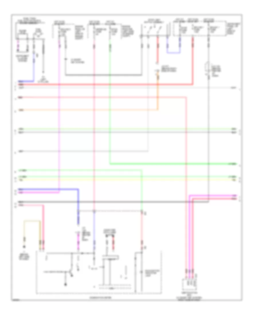
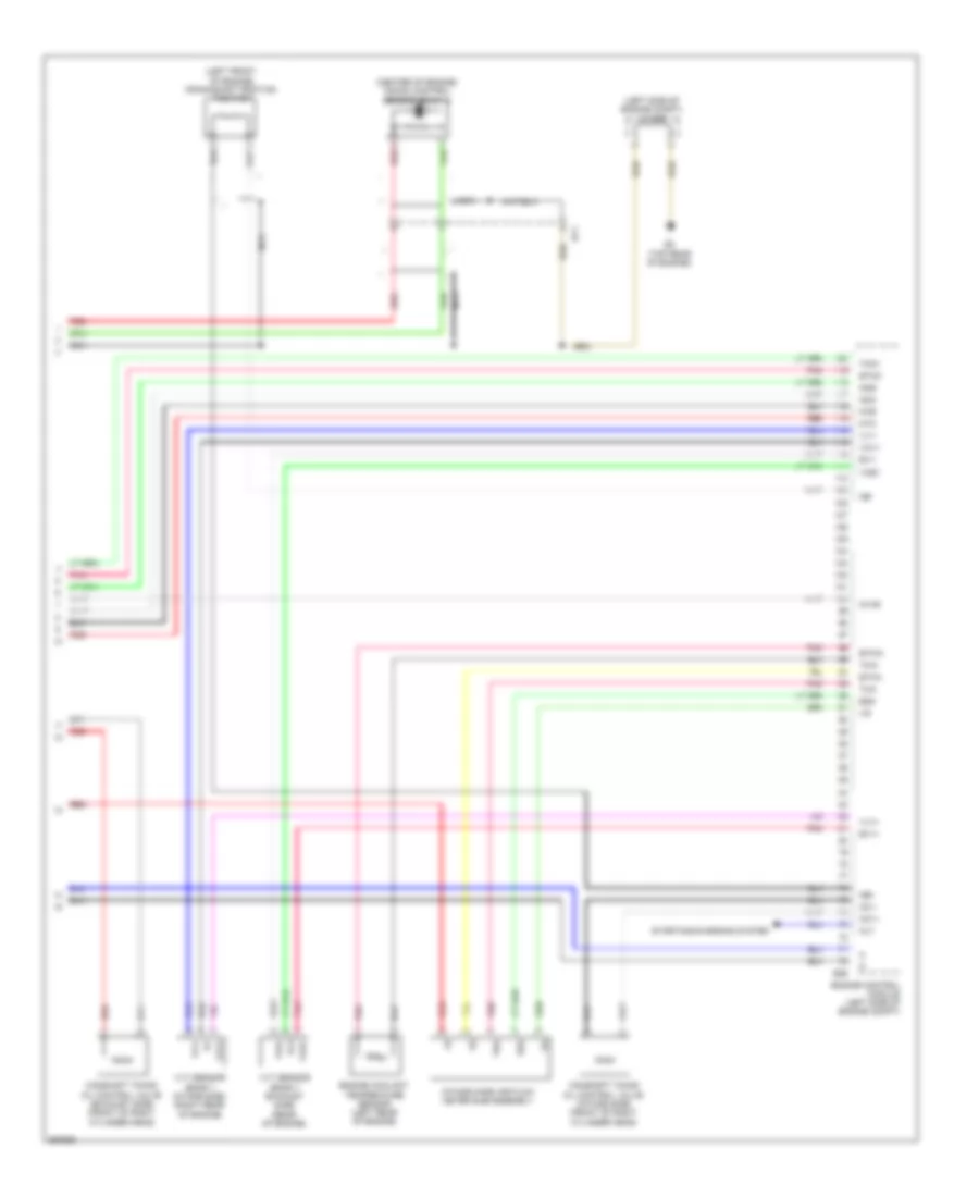
2.5L, Engine Performance Wiring Diagram (1 of 6) for Toyota Camry XLE 2012

List of elements for 2.5L, Engine Performance Wiring Diagram (1 of 6) for Toyota Camry XLE 2012:
- +b2
- A1 (left front of engine compt)
- A25
- Accelerator position sensor (accelerator pedal assembly)
- An1
- Batt
- Brake actuator assembly (right front of engine compt)
- C/opn relay
- C10
- Canh
- Canister pressure sensor
- Canister pump module (left rear of vehicle)
- Canl
- Ccs
- Computer data lines system
- Cruise control system
- Door locks & anti-theft systems
- Door locks system
- E1 (top rear of engine)
- Ea2
- Efi 1 fuse 7.5a
- Efi 2 fuse 15a
- Efi 3 fuse 7.5a
- Efi main 2 relay
- Efi main relay
- Efi- main 1 fuse 30a
- Efi- main 2 fuse 20a
- Engine control module (left side of engine compt)
- Engine room j/b (left side of engine compt)
- Engine room r/b (left side of engine compt)
- Epa
- Epa2
- Eppm
- Fanh
- Fanl
- Hot at all times
- I3 (behind center of dash)
- Ia3
- Ia8
- Ig 2 relay
- Ig2- main fuse 25a
- Igsw
- Imi
- Imo
- Inj fuse 7.5a
- J/c a73 (left front of engine compt)
- J/c i126 (behind center of dash)
- Leak detection pump
- Mpmp
- Mrel
- Neo
- Pnk
- Ppmp
- Red
- Sftd
- Sftu
- Spd
- St1-
- Sta
- Stp
- Tach
- Transmission control switch (lower shift lever assembly)
- Vcp2
- Vcpa
- Vcpp
- Vent valve
- Vpa
- Vpa2
- Vpmp
- W/ headlight beam level control
- W/ paddle shift switch
- W/ smart key system
- W/o paddle shift switch
- W/o smart key system
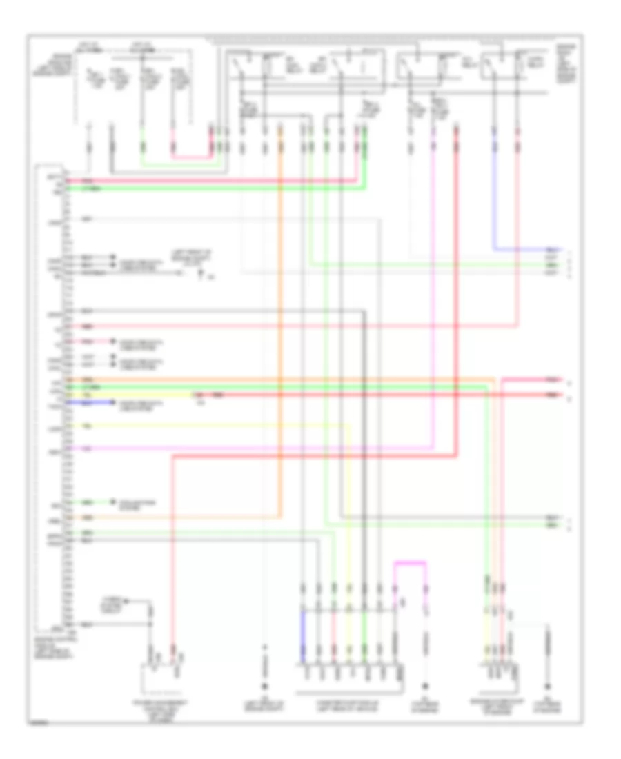
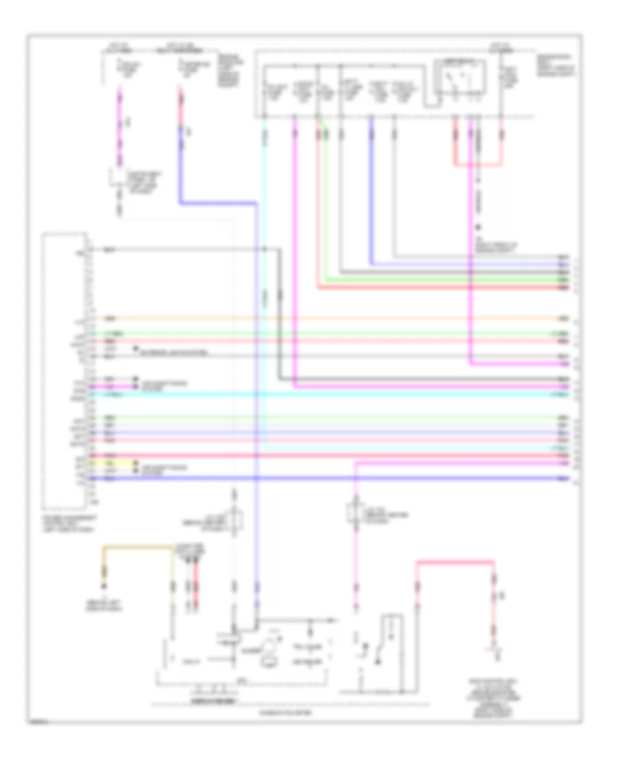
2.5L, Engine Performance Wiring Diagram (2 of 6) for Toyota Camry XLE 2012
List of elements for 2.5L, Engine Performance Wiring Diagram (2 of 6) for Toyota Camry XLE 2012:
- (fuel tank) fuel suction pump & gauge assembly
- 5v 1c
- A43
- A56
- An1
- Can i/f
- Certification ecu (w/ smart key system) (right side of dash)
- Combination meter
- Computer data lines system
- Cpu
- D24
- D30
- Ecu-ig1 1 fuse 10a
- Ecu-ig2 1 fuse 7.5a
- Ecu-ig2 3 fuse 7.5a
- Engine room j/b (left side of engine compt)
- Engine room r/b (left side of engine compt)
- Etcs fuse 10a
- Fuel pump
- Gauge
- Hot at all times
- Hot in on or start
- I/f
- I1 (behind left side of dash)
- I18
- Ia3
- Ig2d
- Instrument cluster system
- Instrument panel j/b (left side of dash)
- J/c a71 (behind right side of dash)
- J/c i124 (behind center of dash)
- Malfunction indicator lamp
- Meter-ig2 fuse 5a
- N1 (left "c" pillar)
- Pnk
- Red
- Sta
- Star
- Stop fuse 7.5a
- Stop light switch assembly
- W/ smart key system
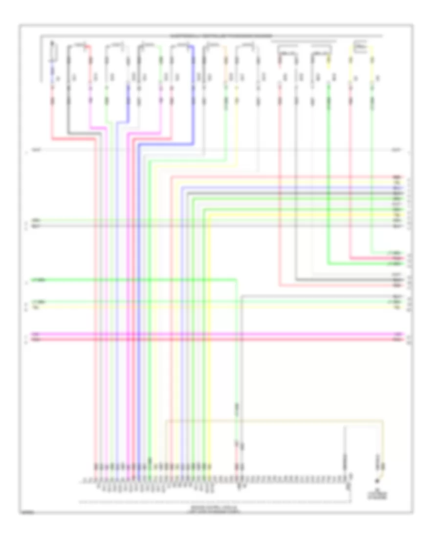
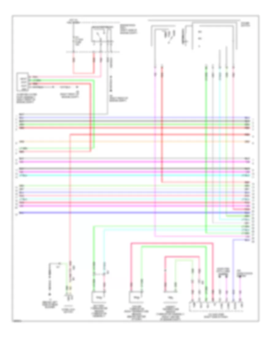
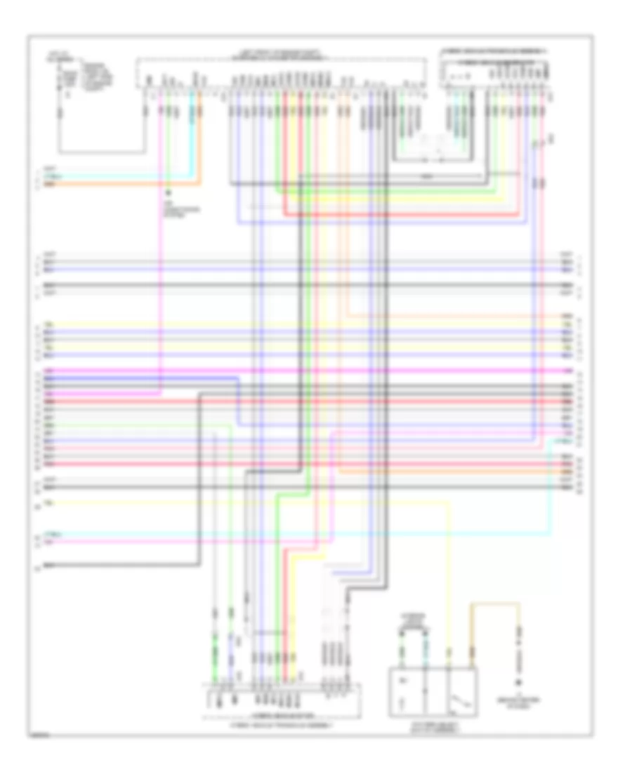
2.5L, Engine Performance Wiring Diagram (3 of 6) for Toyota Camry XLE 2012
List of elements for 2.5L, Engine Performance Wiring Diagram (3 of 6) for Toyota Camry XLE 2012:
- +bm
- E02
- E26
- E3 (top rear of engine)
- Ea2
- Electronically controlled transmission solenoid
- Engine control module (left side of engine compt)
- Ha1a
- Hall ic
- Ht1b
- Ia1+
- Ia1-
- Ncb
- Nco
- Ntb
- Nto
- Oil
- Pnk
- Red
- Sl1+
- Sl1-
- Sl2+
- Sl2-
- Sl3+
- Sl3-
- Sl4+
- Sl4-
- Slt+
- Slt-
- Slu+
- Slu-
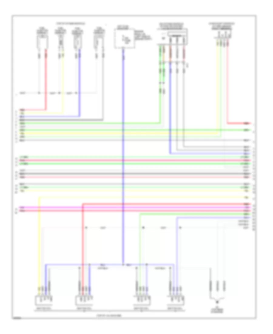
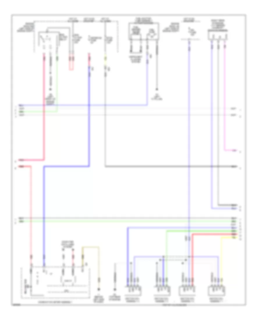
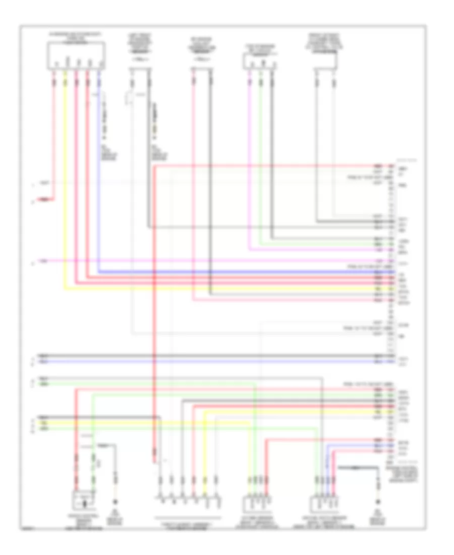
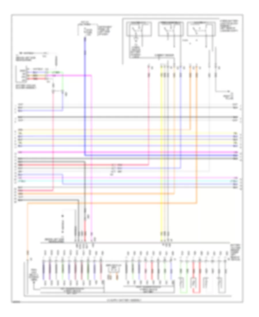
2.5L, Engine Performance Wiring Diagram (4 of 6) for Toyota Camry XLE 2012
List of elements for 2.5L, Engine Performance Wiring Diagram (4 of 6) for Toyota Camry XLE 2012:
- (in exhaust manifold) oxygen sensor (bank 1 sensor 2)
- (on intake manifold) intake air control valve actuator
- (top of intake manifold)
- (top of valve cover)
- E1 (top rear of engine)
- Engine room j/b (left side of engine compt)
- Ey1
- Fuel injector assembly
- Gnd
- Hot in on or start
- Ht1b
- Igf
- Ign fuse 15a
- Ignition coil
- Igt1
- Igt2
- Igt3
- Igt4
- Out
- Ox1b
- Pnk
- Red
- Sensor
- Vdd
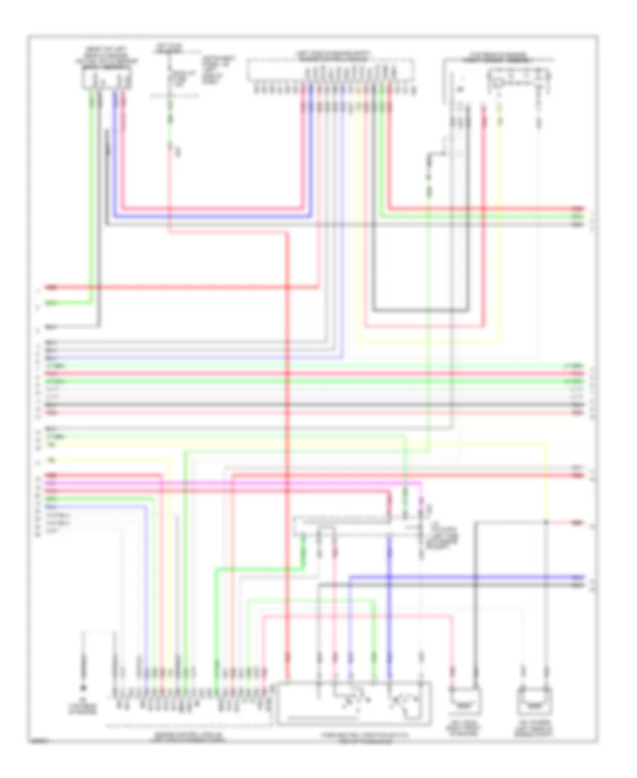
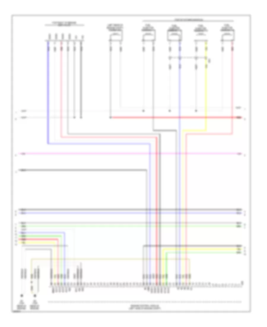
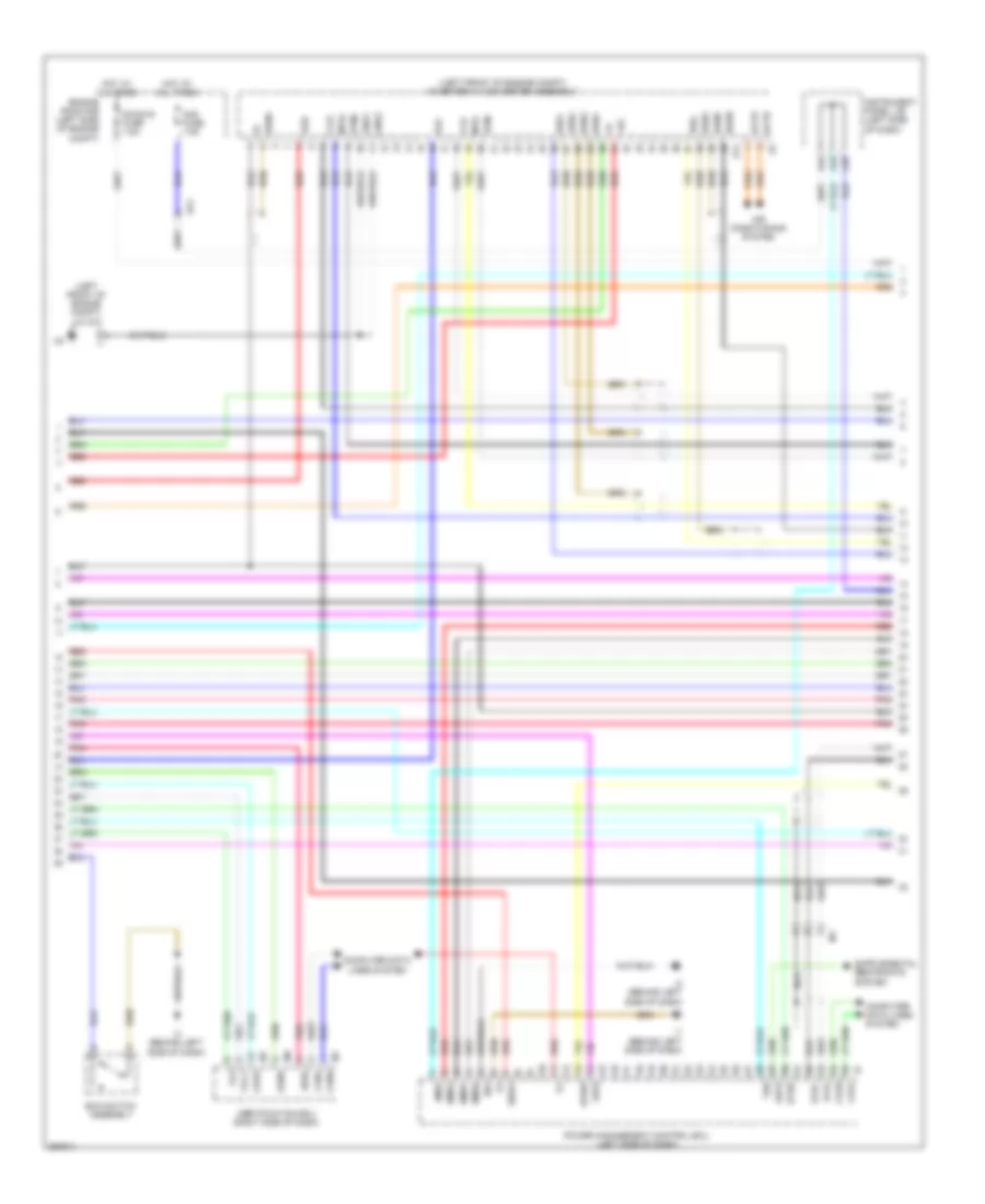
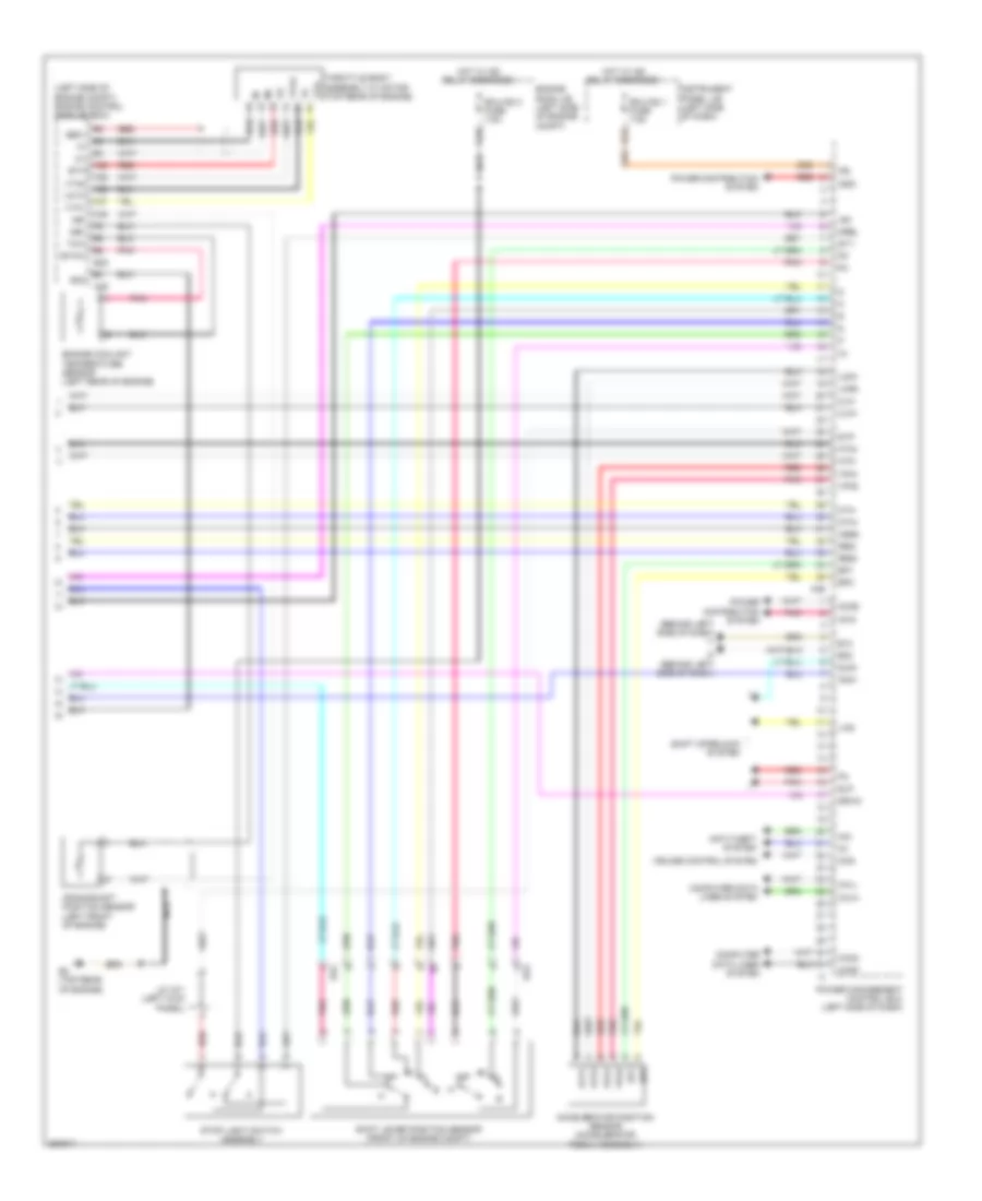
2.5L, Engine Performance Wiring Diagram (5 of 6) for Toyota Camry XLE 2012
List of elements for 2.5L, Engine Performance Wiring Diagram (5 of 6) for Toyota Camry XLE 2012:
- (left side of engine compt) engine control module
- (near top left rear of engine) air fuel ratio sensor (bank 1 sensor 1)
- (top of transaxle)
- (top rear of engine) throttle body assembly
- A1a+
- A1a-
- A70
- Acis
- Back up fuse 7.5a
- Compt)
- D33
- E01
- E04
- E26
- E3 (top rear of engine)
- Ea2
- Eia1
- Eknk
- Engine control module (left side of engine compt)
- Eta
- Ex1b
- Geo1
- Ha1a
- Hot in on or start
- Iac1
- Ic1
- Ic2
- Igf1
- Igt1
- Igt2
- Igt3
- Igt4
- Instrument panel j/b (left side of dash)
- J/c a70 & e76 (left side of engine e76
- Knk1
- Me01
- N r
- Nca
- Nsw
- Oe1+
- Ole-
- Park/neutral position switch
- Pnk
- Prg
- R n
- Red
- Vcia
- Vcta
- Vsv (acis) (right front of engine)
- Vsv (purge) (left rear of engine compt)
- Vta1
- Vta2
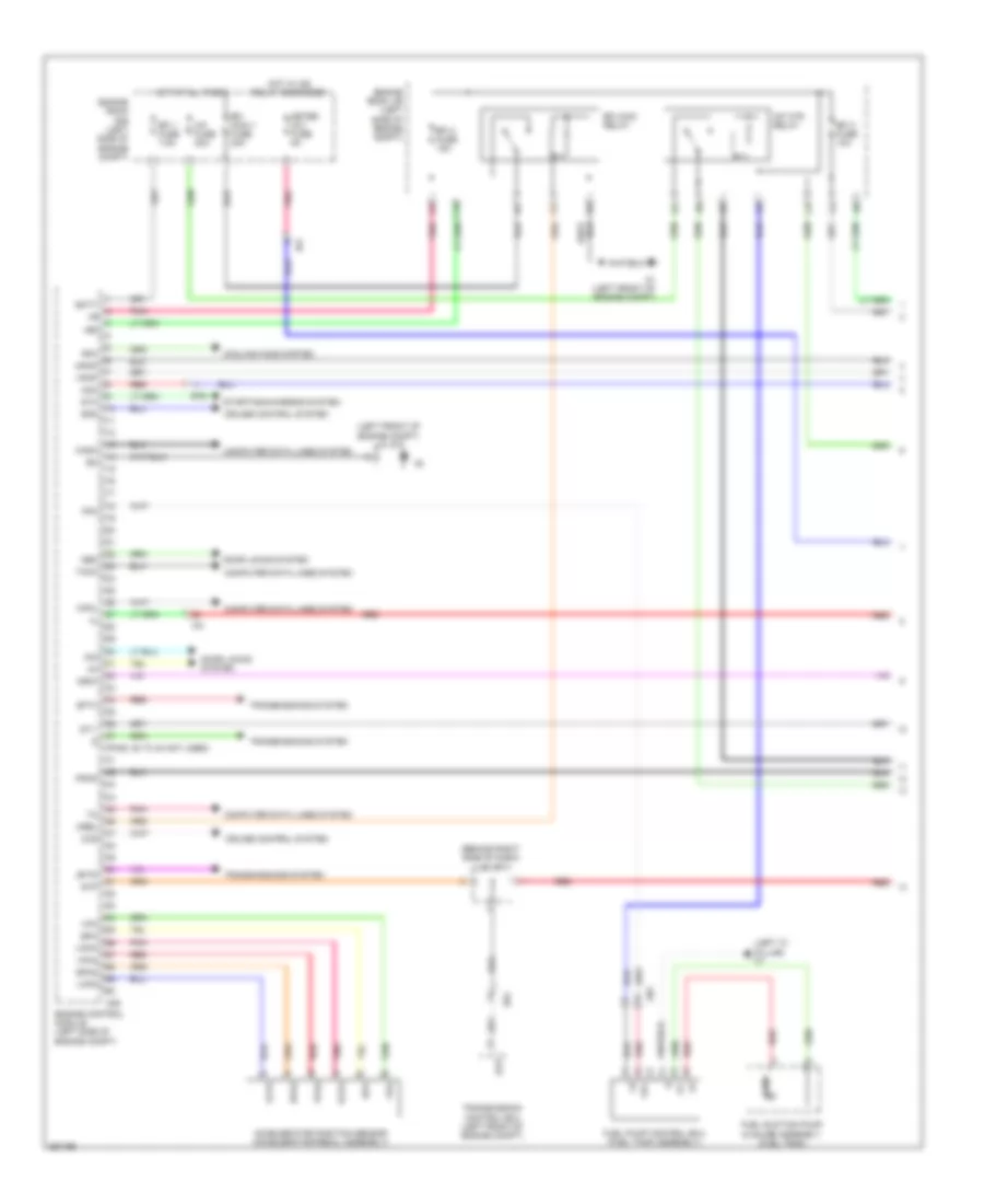
2.5L, Engine Performance Wiring Diagram (6 of 6) for Toyota Camry XLE 2012
List of elements for 2.5L, Engine Performance Wiring Diagram (6 of 6) for Toyota Camry XLE 2012:
- (center of engine) knock control sensor (bank 1)
- (left front of engine) crankshaft position position
- (left side of engine compt) j/c e76
- Alt
- Camshaft timing oil control valve (exhaust side) (front of right cylinder head)
- Camshaft timing oil control valve (intake side) (front of right cylinder head)
- E26
- E2g
- E3 (top rear of engine)
- Engine control module (left side of engine compt)
- Engine coolant temperature sensor (left rear of engine)
- Etha
- Etho
- Ethw
- Ev1+
- Ev1-
- Ey1
- Intake mass air flow meter sub-assembly
- Nca
- Ncb
- Nco
- Ne+
- Ne-
- Ntb
- Nto
- Oc1+
- Oc1-
- Ox1b
- Pnk
- Red
- Starting/charging system
- Tha
- Tho1
- Thw
- Vc2
- Vce1
- Vcv1
- Vv1+
- Vv1-
- Vve+
- Vve-
- Vvt sensor (bank 1 exhaust side) (rear of engine)
- Vvt sensor (bank 1 intake side) (right rear of engine)
2.5L HYBRID
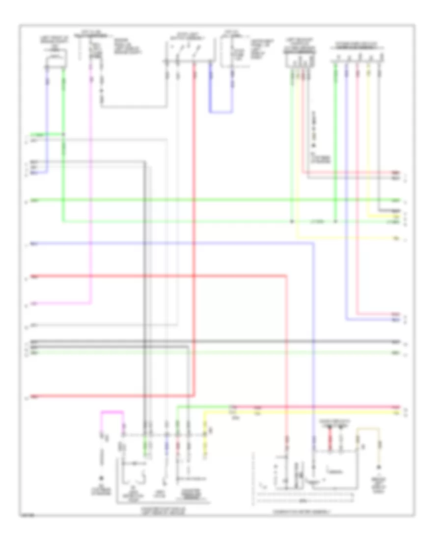
2.5L Hybrid, Engine Controls Wiring Diagram (1 of 4) for Toyota Camry XLE 2012
List of elements for 2.5L Hybrid, Engine Controls Wiring Diagram (1 of 4) for Toyota Camry XLE 2012:
- (left front of engine compt) j/c a73
- +b2
- A25
- A38
- A39
- A5 (left front of engine compt)
- An1
- Batt
- C/opn relay
- C10
- Canh
- Canister pump module (left rear of vehicle)
- Canl
- Cann
- Canp
- Computer data line system
- Computer data lines system
- Cooling fans system
- E1 (top rear of engine)
- E3 (top rear of engine)
- Ea2
- Ecu- ig2 3 fuse 7.5a
- Efi 1 fuse 7.5a
- Efi 2 fuse 15a
- Efi 3 fuse 7.5a
- Efi main 2 relay
- Efi main relay
- Efi- main 1 fuse 30a
- Efi- main 2 fuse 20a
- Engine control module (left side of engine compt)
- Engine room j/b (left side of engine compt)
- Engine room r/b (left side of engine compt)
- Engine water pump (left front of engine)
- Eppm
- G2o
- Hot at all times
- Hybrid system circuit
- Ia3
- Ig 2 relay
- Ig2- main fuse 25a
- Ig2d
- Igsw
- Inj fuse 7.5a
- Mgnd
- Mpmp
- Mrel
- Mtrb
- Nwp
- Pgnd
- Pnk
- Power management control ecu (left side of dash)
- Ppmp
- Red
- Rfc
- Sgnd
- Swp
- Tach
- Vcc
- Vcpp
- Vgnd
- Vlvb
- Vout
- Vpmp
- Wpi
- Wpo
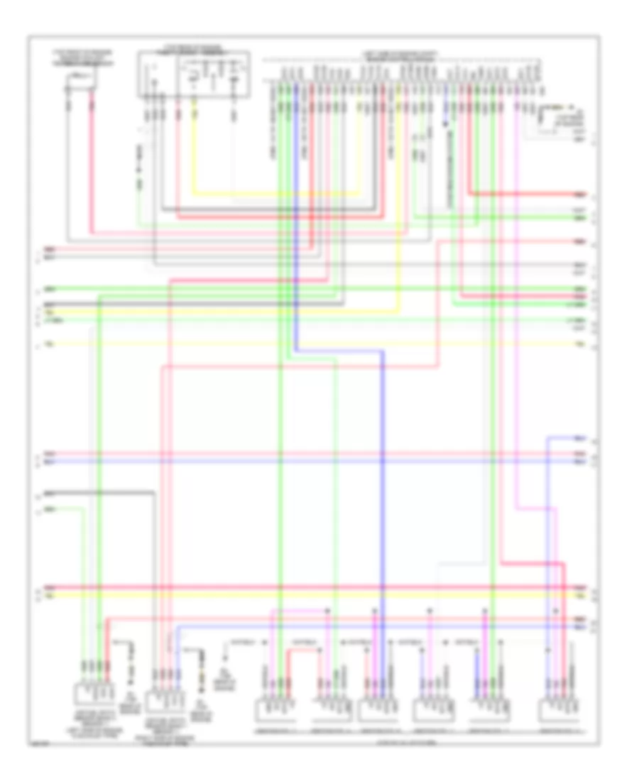
2.5L Hybrid, Engine Controls Wiring Diagram (2 of 4) for Toyota Camry XLE 2012
List of elements for 2.5L Hybrid, Engine Controls Wiring Diagram (2 of 4) for Toyota Camry XLE 2012:
- (right rear of engine) vvt sensor (camshaft position sensor)
- (top of valve cover)
- A5 (left front of engine compt)
- An1
- Can i/f
- Canh
- Canl
- Chk
- Combination meter assembly
- Computer data lines system
- Cpu
- E1 (top rear of engine)
- Ea2
- Eng w/ pmp fuse 30a
- Eng w/ pmp relay
- Engine room j/b (left side of engine compt)
- Engine room r/b (left side of engine compt)
- Etcs fuse 10a
- Fuel pump
- Fuel sender gauge
- Fuel suction tube assembly w/ pump & gauge
- Gnd
- Hot at all times
- Hot in on or start
- I/f
- I1 (behind left side of dash)
- I18
- Ia3
- Ig+
- Igf
- Ign fuse 15a
- Ignition coil assembly 1
- Ignition coil assembly 2
- Ignition coil assembly 3
- Ignition coil assembly 4
- Igt1
- Igt2
- Igt3
- Igt4
- Ind malfunction
- Instrument cluster system
- Meter-ig2 fuse 5a
- N1 (left "c" pillar)
- Pnk
- Red
- Vvi+
- Vvi-
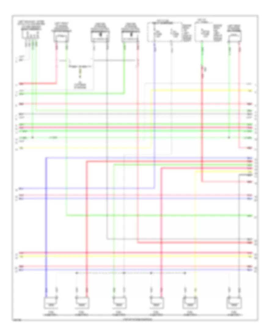
2.5L Hybrid, Engine Controls Wiring Diagram (3 of 4) for Toyota Camry XLE 2012
List of elements for 2.5L Hybrid, Engine Controls Wiring Diagram (3 of 4) for Toyota Camry XLE 2012:
- (left rear of engine compt) purge vsv
- (top of intake manifold)
- (top right of engine) egr valve
- +b1
- +b2
- +bm
- E01
- E02
- E04
- E1 (top rear of engine)
- E28
- E3 (top rear of engine)
- Egr1
- Egr2
- Egr3
- Egr4
- Eh1
- Engine control module (left side of engine compt)
- Fuel injector assembly 1
- Fuel injector assembly 2
- Fuel injector assembly 3
- Fuel injector assembly 4
- Ha1a
- Ht1b
- Igf1
- Igt1
- Igt2
- Igt3
- Igt4
- Me01
- Red
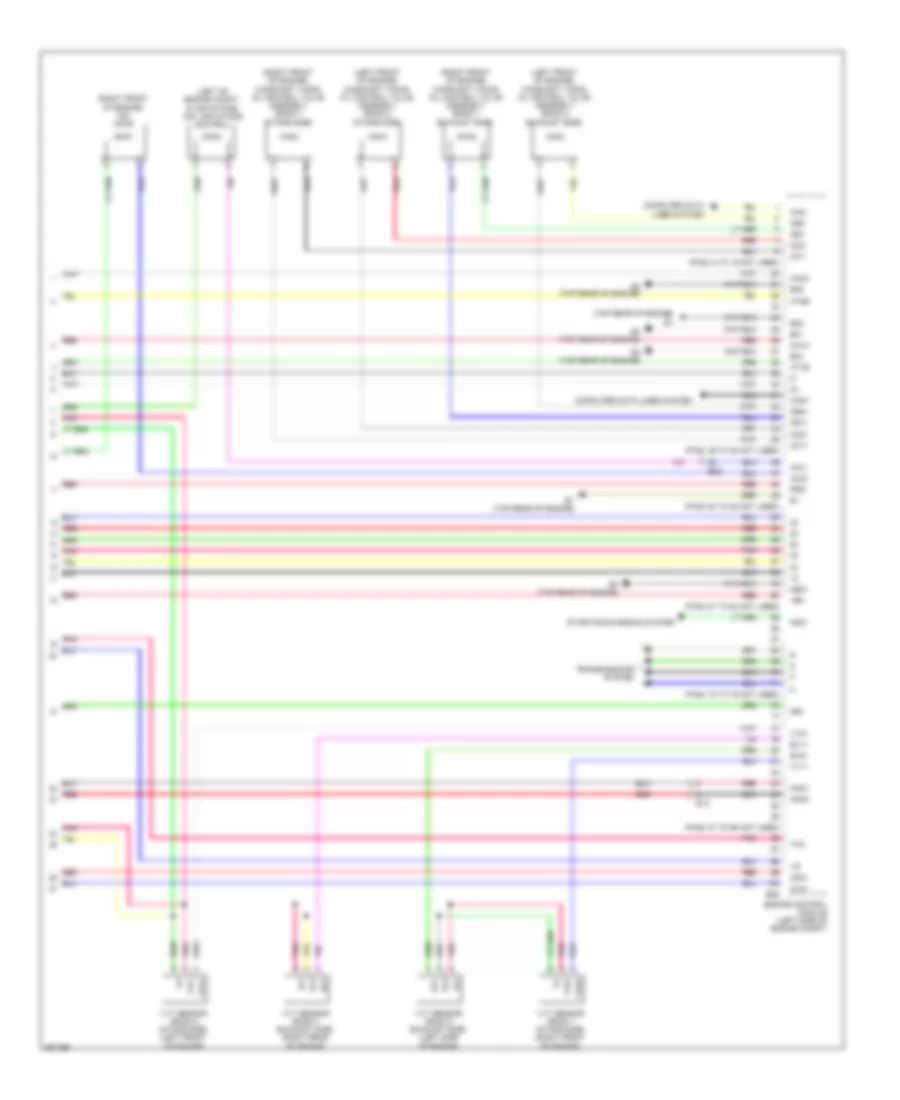
2.5L Hybrid, Engine Controls Wiring Diagram (4 of 4) for Toyota Camry XLE 2012
List of elements for 2.5L Hybrid, Engine Controls Wiring Diagram (4 of 4) for Toyota Camry XLE 2012:
- (front of right cylinder head) camshaft timing oil control valve (intake side)
- (in engine air intake duct) mass air flow meter
- (left front of engine) crankshaft position sensor
- (top of engine) efi vacuum sensor
- A1a+
- A1a-
- Air fuel ratio sensor (bank 1 sensor 1) (near top left rear of engine)
- E28
- E2g
- E3 (top rear of engine)
- Efi engine coolant temperature sensor
- Eknk
- Engine control module (ecm) (left side of engine compt)
- Epim
- Eta
- Etha
- Ethw
- Ex1b
- Ey2
- Ge01
- Ha1a
- Ht1b
- Knk1
- Knock control sensor (bank 1) (center of engine)
- Nca
- Ne+
- Ne-
- Oc1+
- Oc1-
- Ox1b
- Oxygen sensor (bank 1 sensor 2) (in exhaust manifold)
- Pim
- Pins: 101 to 108 not used
- Pins: 115 to 122 not used
- Pins: 61 to 67 not used
- Pins: 83 to 90 not used
- Pnk
- Prg
- Red
- Tha
- Throttle body assembly (top rear of engine)
- Thw
- Vcpm
- Vcta
- Vcv1
- Vta1
- Vta2
- Vv1+
- Vv1-
2.5L Hybrid, Hybrid System Wiring Diagram (1 of 6) for Toyota Camry XLE 2012
List of elements for 2.5L Hybrid, Hybrid System Wiring Diagram (1 of 6) for Toyota Camry XLE 2012:
- +b2
- 5v ic
- A38
- A6 (right front of engine compt)
- Aa1
- Air conditioning system
- B26
- Batt fan fuse 7.5a
- Batt vl ssr fuse 10a
- Buzzer
- Can i/f
- Clk
- Combination meter
- Computer data lines system
- Cpu
- D31
- Dc/dc igct fuse 10a
- Display driver
- Ecu-b 1 fuse 10a
- Engine room r/b (left side of engine compt)
- Engine room r/b 2 (right side of engine compt)
- Eti
- Exterior lights system
- Gmt
- Gmtg
- Hot at all times
- Hot w/ ig2 relay energized
- I/f
- I1 (behind left side of dash)
- Ia3
- Ia8
- Igct relay
- Igct- main fuse 25a
- Ilk
- Instrument panel j/b (left side of dash)
- Inv fuse 7.5a
- Inv w/ pmp rly fuse 7.5a
- Ite
- Iwp
- J/c i124 (behind center of dash)
- J/c i125 (behind center of dash)
- Led driver
- Meter-ig2 fuse 5a
- Mmt
- Mmtg
- Niwp
- Nodd
- Pm igct fuse 7.5a
- Pnk
- Power management control ecu (left side of dash)
- Red
- Sio
- Skid control ecu w/ actuator (brake booster w/ master cylinder assembly) (right side of engine compt)
- Sp1
- Stb
- Telltales
- Vlo
2.5L Hybrid, Hybrid System Wiring Diagram (2 of 6) for Toyota Camry XLE 2012
List of elements for 2.5L Hybrid, Hybrid System Wiring Diagram (2 of 6) for Toyota Camry XLE 2012:
- +bwp
- A/c amplifier (right side of dash)
- A6 (right front of engine compt)
- Agnd
- Air conditioning system
- Ambient temperature sensor (thermistor assembly) (front center of engine compt)
- An3
- Antenna coil
- Battery thermometer sensor (thermistor assembly)
- Canh
- Canl
- Computer data lines system
- Cooler thermistor (room temperature sensor) (behind center of dash)
- Ecos
- Engine room r/b 2 (right side of engine compt)
- Gnd
- Hot at all times
- Ia8
- Ilk
- Inter lock switch
- Inv w/ pmp fuse 15a
- Inv w/ pmp relay
- Inverter water pump assembly (right front of engine compt)
- Io2
- Lin1
- Nwp
- Nr1
- Pnk
- Power switch
- Red
- Sg-1
- Sg-2
- Ss1
- Ss2
- Swp
- T1 (behind left side of rear bumper)
- Tam
2.5L Hybrid, Hybrid System Wiring Diagram (3 of 6) for Toyota Camry XLE 2012
List of elements for 2.5L Hybrid, Hybrid System Wiring Diagram (3 of 6) for Toyota Camry XLE 2012:
- (left front of engine compt) inverter w/ converter assembly
- (left front of engine compt) j/c a73
- +b2
- A14
- A33
- A35
- Aa1
- Abfs
- Acpb
- Acpe
- Agnd
- Air conditioning system
- Am2 fuse 7.5a
- Am22
- Bth+
- Bth-
- Ca2h
- Ca2l
- Canh
- Canl
- Certification ecu (right side of dash)
- Clk+
- Clk-
- Code
- Computer data lines system
- D16
- Dc/dc-s fuse 7.5a
- Drn1
- Drn2
- Drn3
- Drn4
- Drn5
- Drn8
- E01
- Eco switch assembly
- Engine room r/b (left side of engine compt)
- Ethb
- Evsw
- Gnd1
- Gnd2
- Hot at all times
- Hsdn
- Htm+
- Htm-
- I1 (behind left side of dash)
- I2 (behind left side of dash)
- I3 (behind left side of dash)
- I86
- I87
- Ilki
- Ilko
- In1
- Instrument panel j/b (left side of dash)
- Mth+
- Mth-
- Nca
- Pnk
- Power management control ecu (left side of dash)
- Red
- Req+
- Req-
- Smrb
- Smrg
- Smrp
- Spdi
- Ssw1
- Swil
- Thb
- Txct
- Vc5
2.5L Hybrid, Hybrid System Wiring Diagram (4 of 6) for Toyota Camry XLE 2012
List of elements for 2.5L Hybrid, Hybrid System Wiring Diagram (4 of 6) for Toyota Camry XLE 2012:
- (left front of engine compt) inverter w/ converter assembly
- A13
- Air conditioning system
- Amd
- Cbi
- Cei
- Dc/dc fuse 120a
- Drn6
- E12
- E13
- E15
- Ea2
- Engine room j/b (left side of engine compt)
- Gcs
- Gcsg
- Gmt
- Gmtg
- Grf
- Grfg
- Gsn
- Gsng
- Hot at all times
- Hybrid vehicle generator
- Hybrid vehicle motor
- Hybrid vehicle transaxle assembly
- I3 (behind center of dash)
- Idh
- Igct
- Interior lights system
- Mcs
- Mcsg
- Mmt
- Mmtg
- Mrf
- Mrfg
- Mscg
- Msn
- Msng
- Nca
- Nodd
- Pattern select switch assembly
- Pnk
- Red
- Vlo
2.5L Hybrid, Hybrid System Wiring Diagram (5 of 6) for Toyota Camry XLE 2012
List of elements for 2.5L Hybrid, Hybrid System Wiring Diagram (5 of 6) for Toyota Camry XLE 2012:
- An3
- Battery cooling blower assembly
- Battery voltage sensor (under left rear of vehicle)
- Bth+
- Bth-
- Current sensor
- D30
- Fp0
- From main relay 2 (diagram 1 of 5)
- Gb0
- Gb1
- Gb2
- Gbo
- Gc0
- Gib
- Gnd
- Gnd0
- Hot at all times
- Hybrid battery junction block assembly (left rear of luggage compt)
- Ig0
- Igct
- Instrument panel j/b (left side of dash)
- Io2
- Left busbar module hybrid vehicle battery
- Main relay 1
- Main relay 2
- N18
- Nr1
- O1 (right "c" pillar)
- Pnk
- Precharge relay
- Red
- Right busbar module hybrid vehicle battery
- Service plug grip
- Si0
- Stop fuse 7.5a
- T1 (behind left side rear bumper)
- Tb0
- Tb1
- Tb2
- Tco
- Tn1
- To hybrid vehicle battery (diagram 1 of 5)
- Vb1
- Vb10
- Vb11
- Vb12
- Vb13
- Vb14
- Vb15
- Vb16
- Vb17
- Vb2
- Vb3
- Vb4
- Vb5
- Vb6
- Vb7
- Vb8
- Vb9
- Vib
2.5L Hybrid, Hybrid System Wiring Diagram (6 of 6) for Toyota Camry XLE 2012
List of elements for 2.5L Hybrid, Hybrid System Wiring Diagram (6 of 6) for Toyota Camry XLE 2012:
- (behind left side of dash) i1
- (left side of engine compt) engine control module (ecm)
- +b1
- A25
- A39
- Accd
- Accelerator position sensor (accelerator pedal assembly)
- Am21
- Anti-theft system
- Ca1h
- Ca1l
- Ca3n
- Ca3p
- Ccs
- Clk+
- Clk-
- Computer data lines system
- Crankshaft position sensor (left front of engine)
- Cruise control system
- D24
- E02
- E12
- E28
- E3 (top rear of engine)
- Ea2
- Ea3
- Ecu-ig2 1 fuse 7.5a
- Ecu-ig2 3 fuse 7.5a
- Engine coolant temperature sensor (left rear of engine)
- Engine room j/b (left side of engine compt)
- Ep1
- Ep2
- Eta
- Ethw
- G2o
- Ge01
- Hot w/ ig2 relay energized
- Hsdn
- Htm+
- Htm-
- I2 (behind left side of dash)
- Ig1d
- Ig2
- Ig2d
- Imi
- Imo
- Instrument panel j/b (left side of dash)
- J/c a71 (left kick panel)
- Lin2
- Mrel
- Mth+
- Mth-
- Nca
- Ne+
- Ne-
- Pnk
- Power distribution system
- Power management control ecu (left side of dash)
- Red
- Req+
- Req-
- Shift interlock system
- Shift lever position sensor (front of engine compt)
- Slp
- Slr+
- Ssw2
- St1-
- Stop light switch assembly
- Stp
- Throttle body assembly w/ motor (top rear of engine)
- Thw
- Vcp1
- Vcp2
- Vcta
- Vpa1
- Vpa2
- Vta
- Vta1
- Vta2
3.5L
3.5L, Engine Performance Wiring Diagram (1 of 5) for Toyota Camry XLE 2012
List of elements for 3.5L, Engine Performance Wiring Diagram (1 of 5) for Toyota Camry XLE 2012:
- (behind right side of dash) j/c a71
- (left "c" pillar) n1
- (left front of engine compt) j/c a73
- (pins: 38 to 40 not used)
- +b2
- A/f fuse 20a
- A/f htr relay
- A1 (left front of engine compt)
- A25
- Accelerator position sensor (accelerator pedal assembly)
- Acm
- An1
- Batt
- C10
- Canh
- Canl
- Ccs
- Computer data lines system
- Cooling fans system
- Cruise control system
- Door locks system
- Ea2
- Efi 1 fuse 7.5a
- Efi 2 fuse 15a
- Efi 3 fuse 10a
- Efi main 1 fuse 30a
- Efi main relay
- Engine control module (left side of engine compt)
- Engine room j/b (left side of engine compt)
- Engine room r/b (left side of engine compt)
- Epa
- Epa2
- Fp-
- Fpc
- Fuel pump control ecu (fuel tank assembly)
- Fuel suction pump & gauge assembly (fuel tank)
- Hot at all times
- Hot w/ ig2 relay energized
- Ia3
- Igsw
- Imi
- Imo
- Meter ig 2 fuse 5a
- Mpmp
- Mrel
- Neo
- Pnk
- Ppmp
- Pump
- Red
- Rfc
- Sftd
- Sftu
- Spd
- St1-
- Sta
- Starting/charging system
- Stp
- Tach
- Transmission control ecu (left front of engine compt)
- Transmissions system
- Vcp2
- Vcpa
- Vpa
- Vpa2
- Vpmp
3.5L, Engine Performance Wiring Diagram (2 of 5) for Toyota Camry XLE 2012
List of elements for 3.5L, Engine Performance Wiring Diagram (2 of 5) for Toyota Camry XLE 2012:
- (left exhaust manifold) oxygen sensor (bank 2 sensor 2)
- (left front of engine compt) vsv (acm)
- 5v ic
- An1
- Can if
- Canister pressure sensor
- Canister pump module (left rear of vehicle)
- Combination meter assembly
- Computer data lines system
- Cpu
- D30
- E1 (top rear of engine)
- E2 (top rear of engine)
- E2g
- Ea2
- Ecu ig2 3 fuse 7.5a
- Engine room j/b (left side of engine compt)
- Hot at all times
- Hot w/ ig2 relay energized
- Ht2b
- I/f
- I1 (behind left side of dash)
- I18
- Ind malfunction
- Instrument panel j/b (left side of dash)
- Intake mass air flow meter sub-assembly
- Leak detection pump
- Nca
- Ox2b
- Pnk
- Red
- Stop fuse 7.5a
- Stop light switch assembly
- Tha
- Vent valve
3.5L, Engine Performance Wiring Diagram (3 of 5) for Toyota Camry XLE 2012
List of elements for 3.5L, Engine Performance Wiring Diagram (3 of 5) for Toyota Camry XLE 2012:
- (left side of engine compt) engine control module
- (pins: 119 to 124 not used)
- (pins: 135 to 137 not used)
- (pins: 141 to 160 not used)
- (top front of engine) engine coolant temperature sensor
- (top of valve cover)
- (top rear of engine)
- (top rear of engine) throttle body assembly
- A1a+
- A1a-
- A2a+
- A2a-
- Air fuel ratio sensor (bank 1 sensor 1) (right side of engine, in exhaust pipe)
- Air fuel ratio sensor (bank 2 sensor 1) (left side of engine, in exhaust pipe)
- Alt
- E1 (top rear of engine)
- E26
- E2g
- Ekn2
- Eknk
- Eta
- Etha
- Ethw
- Ex1b
- Ex2b
- Ey3
- Ge01
- Gnd
- Ha1a
- Ha2a
- Ic1
- Ic2
- Igf
- Igf1
- Ignition coil 1
- Ignition coil 2
- Ignition coil 3
- Ignition coil 4
- Ignition coil 5
- Ignition coil 6
- Igt1
- Igt2
- Igt3
- Igt4
- Igt5
- Igt6
- Nca
- Ne-
- Ox1b
- Ox2b
- Pnk
- Red
- Starting/charging system
- Thw
- Vcta
- Vcv1
- Vta1
- Vta2
- Vv1-
3.5L, Engine Performance Wiring Diagram (4 of 5) for Toyota Camry XLE 2012
List of elements for 3.5L, Engine Performance Wiring Diagram (4 of 5) for Toyota Camry XLE 2012:
- (center of engine) knock control sensor (bank 1)
- (center of engine) knock control sensor (bank 2)
- (left exhaust, after catalytic converter) oxygen sensor (bank 1 sensor 2)
- (left front of engine) crankshaft position sensor
- (left rear of engine) vsv (purge)
- (left side of engine compt)
- (top of intake manifold)
- E1 (top rear of engine)
- Ea2
- Engine room j/b
- Engine room r/b (left side of engine compt)
- Etcs fuse 10a
- Fuel injector 1
- Fuel injector 2
- Fuel injector 3
- Fuel injector 4
- Fuel injector 5
- Fuel injector 6
- Hot at all times
- Hot w/ ig2 relay energized
- Ht1b
- Ign fuse 15a
- Inj fuse 7.5a
- Nca
- Ox1b
- Pnk
- Red
3.5L, Engine Performance Wiring Diagram (5 of 5) for Toyota Camry XLE 2012
List of elements for 3.5L, Engine Performance Wiring Diagram (5 of 5) for Toyota Camry XLE 2012:
- (left front of engine) camshaft timing oil control valve assembly (bank 2 exhaust side)
- (left front of engine) camshaft timing oil control valve assembly (bank 2 intake side)
- (left of engine compt, in air intake) vsv (air intake control)
- (pins: 36 to 45 not used)
- (pins: 50 to 52 not used)
- (pins: 6 to 19 not used)
- (pins: 61 to 64 not used)
- (pins: 72 to 75 not used)
- (pins: 87 to 95 not used)
- (right front of engine) camshaft timing oil control valve assembly (bank 1 exhaust side)
- (right front of engine) camshaft timing oil control valve assembly (bank 1 intake side)
- (right front of engine) vsv (acis)
- (top rear of engine)
- +bm
- A1a+
- A2a+
- Acis
- Aicv
- Can+
- Can-
- Computer data lines system
- E01
- E02
- E04
- E05
- E1 (top rear of engine)
- E2 (top rear of engine)
- E26
- E4 (top rear of engine)
- Ea2
- Engine control module (left side of engine compt)
- Ev1+
- Ev2+
- Ex+
- Ex-
- Ey3
- Ha1a
- Ha2a
- Ht1b
- Ht2b
- Knk1
- Knk2
- Me01
- Ne+
- Nsw
- Oc1+
- Oc1-
- Oc2+
- Oc2-
- Oe1+
- Oe1-
- Oe2+
- Oe2-
- Pnk
- Prg
- Red
- Starting/charging system
- Tha
- Transmissions system
- Vc2
- Vv1+
- Vv2+
- Vvl+
- Vvl-
- Vvr+
- Vvr-
- Vvt sensor (bank 1 exhaust side) (right rear of engine)
- Vvt sensor (bank 1 intake side) (right front of engine)
- Vvt sensor (bank 2 exhaust side) (left side of engine)
- Vvt sensor (bank 2 intake side) (left front of engine)