ENGINE PERFORMANCE
1.8L
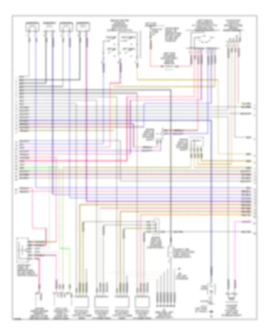
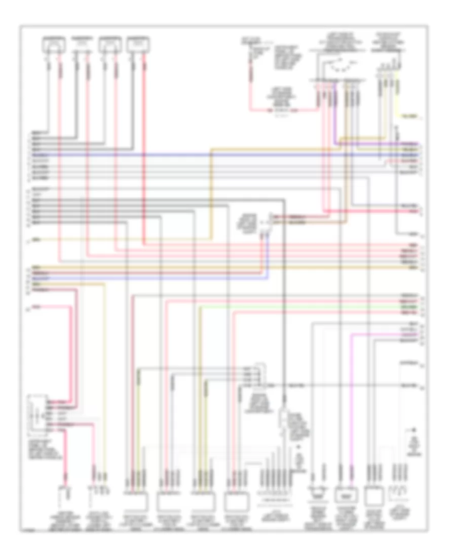
1.8L, Engine Performance Wiring Diagram, GT-S (1 of 4) for Toyota Celica GT 2005

List of elements for 1.8L, Engine Performance Wiring Diagram, GT-S (1 of 4) for Toyota Celica GT 2005:
- (behind panel on left side of center console)
- (behind upper left center of dash)
- (below accelerator pedal)
- (front of left front fender) em
- (pins 30-35 not used)
- +bm
- A/c system
- A/t oil temp
- Acc
- Accelerator pedal position sensor
- Acis vsv (left front of eng compt)
- Acmg
- B10
- B11
- B12
- Batt
- Body ecu (below center console)
- C/opn relay
- C10
- C11
- C12
- C13
- C14
- C15
- C16
- C23
- C24
- C25
- C26
- Ccs
- Check engine
- Combination meter
- Cruise control system
- Efi 1 fuse 10a
- Efi 2 fuse 10a
- Efi fuse 20a
- Efi relay
- Engine control module (left side of engine compt)
- Engine room j/b (left side of engine compartment)
- Engine room r/b 1 (left side of engine compartment)
- Epa
- Epa2
- Etcs fuse 10a
- Exterior lights system
- F/ps
- F10
- F11
- F12
- F14
- F15
- F18
- F19
- Hot at all times
- Hot in on or start
- I12
- If (behind lower center of dash)
- Ig2 fuse 15a
- Ig2 relay
- Ignition switch
- Igsw
- Ind
- Instrument panel j/b
- Instrument panel j/b (behind panel on left side of center console)
- J/c 6
- Lock
- M11
- M12
- M20
- Mpx1
- Mpx2
- Mrel
- N19
- O/d main switch (below center console)
- Odlp
- Odms
- Pnk
- Pressure switching valve (vsv) (under left rear of vehicle)
- Ptnk
- Sat
- Sftd
- Sftu
- Sg4
- Sil
- Spd
- Sports a/t1
- Sports a/t2
- Sports a/t3
- Sports a/t4
- St1-
- Start
- Stp
- Tach
- Tbp
- Vcp2
- Vcpa
- Vpa
- Vpa2
- Warning fuse 5a
- Wfse
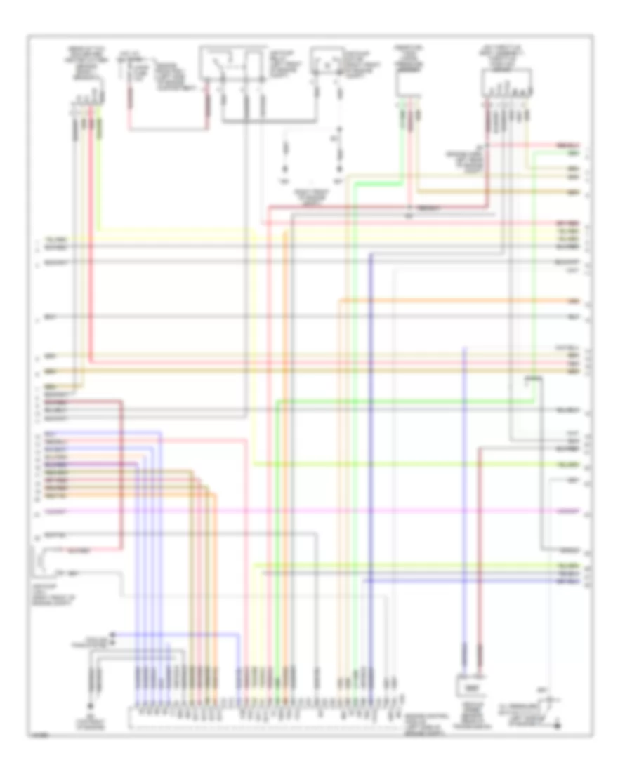
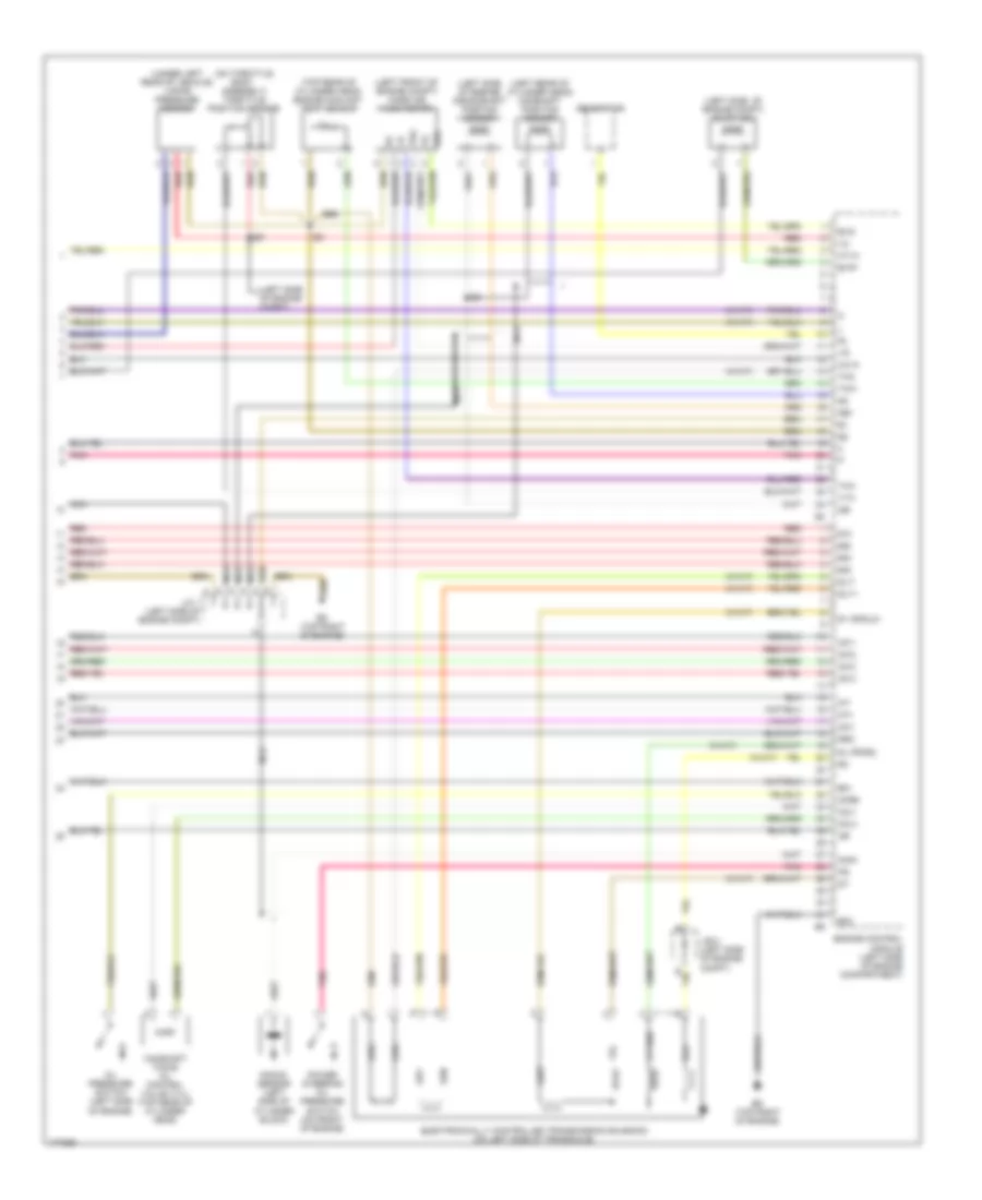
1.8L, Engine Performance Wiring Diagram, GT-S (2 of 4) for Toyota Celica GT 2005
List of elements for 1.8L, Engine Performance Wiring Diagram, GT-S (2 of 4) for Toyota Celica GT 2005:
- (behind center console) transmission shift switch (combination switch)
- (left side of engine compartment) engine room j/b
- (left side of transmission) a/t indicator switch (park/neutral position switch)
- (on exhaust manifold) heated oxygen sensor (bank 1 sensor 1)
- (top left of engine)
- B14
- Back-up fuse 5a
- C12
- C13
- C17
- C19
- C30
- C31
- C32
- Canister closed valve (vsv) (left side of engine compt)
- Center airbag sensor assembly (behind lower center of dash)
- Data link connector 3 (partial) (under left side of dash)
- E1 (eng harn, left center of engine compt)
- Engine room j/b (left side of engine compartment)
- Engine room j/b (left side of engine compt)
- F13
- F22
- F25
- F26
- Fuel pump
- Gsw2
- Hot in on or start
- Ignition coil & igniter 1 (top of cylinder head)
- Ignition coil & igniter 2 (top of cylinder head)
- Ignition coil & igniter 3 (top of cylinder head)
- Ignition coil & igniter 4 (top of cylinder head)
- Injector 1
- Injector 2
- Injector 3
- Injector 4
- Instrument panel j/b (behind panel on left side of center console)
- J/c 14 (left side of trunk)
- Left-down
- Left-up
- Noise filter (ignition system) (left side of engine compt)
- Ox1a
- Pnk
- Right-down
- Right-up
- Sil
1.8L, Engine Performance Wiring Diagram, GT-S (3 of 4) for Toyota Celica GT 2005
List of elements for 1.8L, Engine Performance Wiring Diagram, GT-S (3 of 4) for Toyota Celica GT 2005:
- (engine harn, left rear of engine compt)
- (near fuel tank) vapor pressure sensor
- (on throttle body assembly) throttle position motor
- (rear of twc converter) heated oxygen sensor (bank 1, sensor 2)
- (right front of engine compt)
- A-pmp fuse 10a
- Aip
- Air pump (vsv) (right front of engine compt)
- Air pump motor (right front of engine compt)
- Air pump relay (left front of engine compt)
- Airv
- Cooling fans system
- E01
- E02
- E10
- Ed (top right of engine)
- Engine control module (left side of engine compt)
- Engine room r/b 1 (left side of engine compartment)
- Fan
- Hot at all times
- Ht2
- Igf
- Igt1
- Igt2
- Igt3
- Igt4
- Ne+
- Ne-
- Oil pressure switch (vvtl) (left side of engine)
- Ox1b
- Red
- Shield
- Slt+
- Slt-
- Tha
- Tho
- Thw
- Vehicle speed sensor (rear of transmission)
- Vsv
- Vta
- Vta2
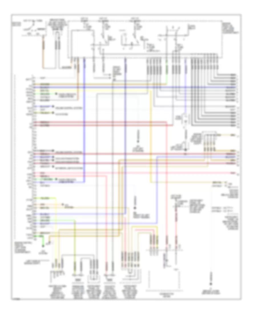
1.8L, Engine Performance Wiring Diagram, GT-S (4 of 4) for Toyota Celica GT 2005
List of elements for 1.8L, Engine Performance Wiring Diagram, GT-S (4 of 4) for Toyota Celica GT 2005:
- (left front of engine compt) mass air flow meter
- (left rear of cylinder head) camshaft position sensor
- (left side of engine compt) evap vsv
- (lower left of engine) crankshaft position sensor
- (top rear of cylinder head) engine coolant temp sensor
- (under left rear of vehicle) vapor pressure sensor
- A/c system
- Airp
- Camshaft timing oil control valve (vvl) (front left of cylinder head)
- Camshaft timing oil control valve (vvt)
- Ccv
- Dsl
- E03
- E11
- E12
- E2g
- Eb (right front fender)
- Ec (left side of cylinder head)
- Ed (top right of engine)
- Eknk
- Electronically controlled transmission solenoid (on left side of transaxle)
- Engine control module (left side of engine compt)
- Engine room j/b (left side of engine compartment)
- Evg
- Evp1
- F20
- Ge01
- Generator
- Hot in start
- Ht1a
- Ht1b
- J/c 1 (left side of engine compt)
- Knk1
- Knock sensor (left side of cylinder block)
- Lcki
- Me01
- Mops
- Nc+
- Nc-
- Nca
- Nt+
- Nt-
- O/d direct clutch speed sensor (left side of trans)
- Ocv+
- Ocv-
- Oil pressure switch (left side of engine)
- Osw
- Ovl+
- Ovl-
- Ox1a
- Ox1b
- Pnk
- Power steering oil pressure switch (left side of engine)
- Red
- Shield
- Sl1+
- Sl1-
- Sl2+
- Sl2-
- St fuse 7.5a
- Sta
- Tha
1.8L, Engine Performance Wiring Diagram, GT (1 of 3) for Toyota Celica GT 2005
List of elements for 1.8L, Engine Performance Wiring Diagram, GT (1 of 3) for Toyota Celica GT 2005:
- (behind panel on left side of center console) instrument panel j/b
- (front of left front fender) em
- (left side of engine compt)
- A/c system
- Acc
- Acmg
- Acoustic control induction system vsv (left front of eng compt)
- B10
- B11
- B12
- Batt
- C/opn relay
- C10
- C11
- C12
- C13
- C14
- C15
- C16
- C23
- C24
- C25
- C26
- Check engine
- Combination meter
- Computer data lines system
- Cooling fans system
- Cruise control system
- E03
- Eb (front of left front fender)
- Ec (top left of engine)
- Efi 1 fuse 10a
- Efi 2 fuse 10a
- Efi fuse 20a
- Efi relay
- Engine control module (left side of engine compartment)
- Engine room j/b (left side of engine compartment)
- Engine room j/b (left side of engine compt)
- Exterior lights system
- F/ps
- F10
- F11
- F12
- F13
- F14
- F15
- F18
- F19
- F20
- F25
- F26
- F27
- Fan
- Fuel pump
- Heated oxygen sensor (bank 1, sensor 2) (rear of twc converter)
- Hot at all times
- Hot in on or start
- Hot in start
- Ht1b
- Ht2
- I12
- Idlo
- If (behind lower center of dash)
- Ig2 fuse 15a
- Ig2 relay
- Ignition switch
- Igsw
- Ind
- Instrument panel j/b (behind panel on left side of center console)
- J/c 14 (left side of trunk)
- Lcki
- Lock
- M11
- M12
- Mpx1
- Mpx2
- Mrel
- N19
- O/d main switch (below center console)
- Od1
- Odlp
- Odms
- Ox1b
- Pnk
- Pre
- Pressure switching valve (vsv) (under left rear of vehicle)
- Ptnk
- Sil
- Spd
- St fuse 7.5a
- Sta
- Start
- Stp
- Tach
- Tbp
- Vsv
- Warning fuse 5a
1.8L, Engine Performance Wiring Diagram, GT (2 of 3) for Toyota Celica GT 2005
List of elements for 1.8L, Engine Performance Wiring Diagram, GT (2 of 3) for Toyota Celica GT 2005:
- (left side of engine compartment) engine room j/b
- (left side of transmission) a/t indicator switch (park/neutral position switch)
- (on exhaust manifold) heated oxygen sensor (bank 1 sensor 1)
- B14
- Back-up fuse 5a
- C12
- C13
- C17
- C19
- C30
- C31
- C32
- Canister closed valve (vsv) (right side of engine compt)
- Center airbag sensor assembly (behind lower center of dash)
- Data link connector 3 (partial) (under left side of dash)
- Ec (top left of engine)
- Ed (top right of engine)
- Engine room j/b (left side of engine compartment)
- Engine room j/b (left side of engine compt)
- F22
- Gsw2
- Hot in on or start
- Idle air control valve (left rear of engine)
- Ignition coil & igniter 1 (top of cylinder head)
- Ignition coil & igniter 2 (top of cylinder head)
- Ignition coil & igniter 3 (top of cylinder head)
- Ignition coil & igniter 4 (top of cylinder head)
- Injector 1
- Injector 2
- Injector 3
- Injector 4
- Instrument panel j/b (behind panel on left side of center console)
- J/c 2 (left side of engine compt)
- Nca
- Noise filter (ignition system) (left side of engine compt)
- Ox1a
- Pnk
- Red
- Sil
- Vehicle speed sensor (ect) (right side of transmission)
1.8L, Engine Performance Wiring Diagram, GT (3 of 3) for Toyota Celica GT 2005
List of elements for 1.8L, Engine Performance Wiring Diagram, GT (3 of 3) for Toyota Celica GT 2005:
- #10
- #20
- #30
- #40
- (left front of engine compt) mass air flow meter
- (left rear of cylinder head) camshaft position sensor
- (left side of engine compt) evap vsv
- (left side of engine compt)
- (left side of engine) crankshaft position sensor
- (on throttle body assembly) throttle position sensor
- (top rear of cylinder head) engine coolant temp sensor
- (under left rear of vehicle) vapor pressure sensor
- (w/a/t)
- Camshaft timing oil control valve (vvl) (top rear of cylinder head)
- Ccv
- E01
- E02
- E2g
- Ed (top right of engine)
- Electronically controlled transmission solenoid (on left side of transaxle)
- Engine control module (left side of engine compartment)
- Evg
- Evp1
- Generator
- Ht1a
- Igf
- Igt1
- Igt2
- Igt3
- Igt4
- J/b 2 (left side of engine compt)
- J/c 1 (left side of engine compt)
- Knk1
- Knock sensor (left side of cylinder block)
- Mops
- Nca
- Ne+
- Ne-
- Nt+
- Nt-
- Ocv+
- Ocv-
- Oil pressure switch (left side of engine)
- Ox1a
- Pnk
- Power steering oil pressure switch (on front of engine)
- Red
- Rso
- S1 or sl2+
- Sl or dsl
- Slt+
- Slt-
- Tha
- Tho
- Thw
- Vta