ENGINE PERFORMANCE
1.8L
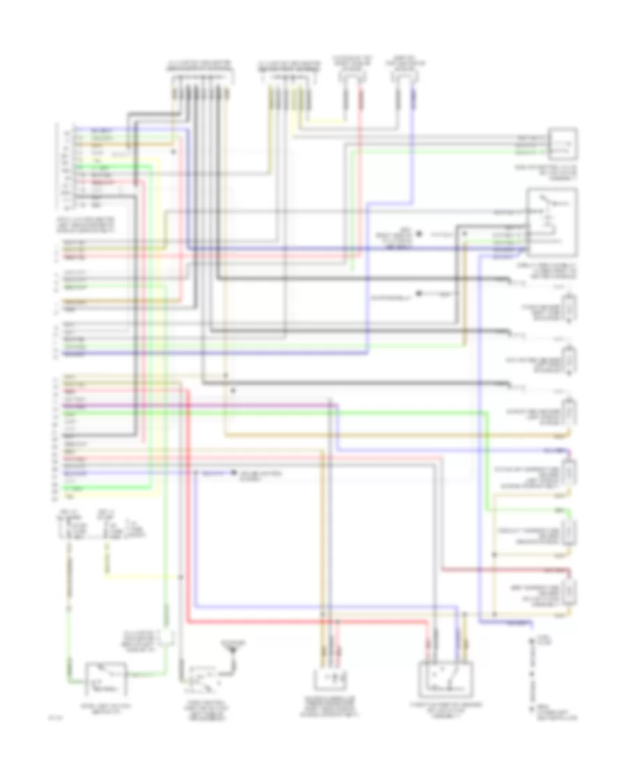
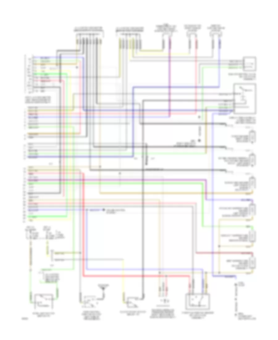
1.8L, Engine Performance Wiring Diagrams, A/T (1 of 2) for Toyota Celica ST 1994

List of elements for 1.8L, Engine Performance Wiring Diagrams, A/T (1 of 2) for Toyota Celica ST 1994:
- #10
- #20
- (behind center
- A/c amplifier
- Aca
- Act
- B/k
- B13
- Batt
- Distributor
- E01
- E02
- Efi fuse 15a
- Efi main relay (r/b #2)
- Egr
- Electronic controlled transmission ecu (a/t) engine control module (m/t) of console)
- Els
- G100 (left front fender)
- G131 (intake manifold)
- Gauge fuse 10a
- Hot at all times
- Hot in run
- Hot in start or run
- Hot with defog on
- Hot with light sw on
- I/p junction block
- Idl
- Idle-up diode
- Ig+
- Ig-
- Igf
- Ign fuse 7.5a
- Igniter
- Ignition coil
- Igt
- Injector #1
- Injector #2
- Injector #3
- Injector #4
- Instrument cluster
- Isc
- Iscc
- Isco
- Knk
- Mal- func ind
- Mir-htr fuse 10a
- Nca
- Ne-
- Nsw
- Ox1
- Ox2
- Pim
- Pnk
- R/b #2
- Red
- Spd
- Speed sensor (rear of engine)
- Speedo
- Sta
- Tail fuse 15a
- Te1
- Te2
- Tha
- Thg
- Thw
- Vta
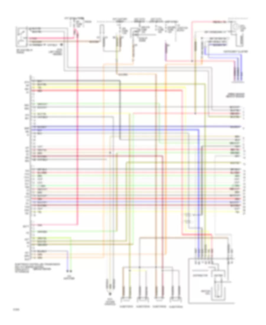
1.8L, Engine Performance Wiring Diagrams, A/T (2 of 2) for Toyota Celica ST 1994
List of elements for 1.8L, Engine Performance Wiring Diagrams, A/T (2 of 2) for Toyota Celica ST 1994:
- A/c idle-up vsv (right side of engine)
- Circuit opening relay (under front of center console)
- Coolant temperature sensor (rear of engine)
- Cruise control system
- Data link connector (left rear corner of engine compartment)
- Egr temperature sensor (on air intake assembly)
- Egr vsv (top center of engine)
- F11
- Fuel pump
- G201 (right side of i/p at r/b #4 set bolt)
- G904 (under left center pillar)
- Hot at all times
- Hot in start
- I/p fuse block
- Idle air control valve (on air intake assembly)
- Ig-
- Intake air temperature sensor (left side of engine compartment)
- J2 junction connector (behind left side of i/p)
- J3 junction connector (behind front console)
- J4 junction connector (behind front console)
- Knock sensor (right side of engine)
- Main oxygen sensor (left side of engine)
- Manifold absolute pressure sensor (right rear side of engine compartment)
- Nca
- Ox1
- Ox2
- P/n
- Park/neutral position switch (left side of transmission)
- Pim
- Red
- St fuse 7.5a
- Starter relay
- Stop fuse 15a
- Stop light switch (behind i/p)
- Sub oxygen sensor (left side of engine)
- Te1
- Te2
- Throttle position sensor (on air intake assembly)
- Vf1
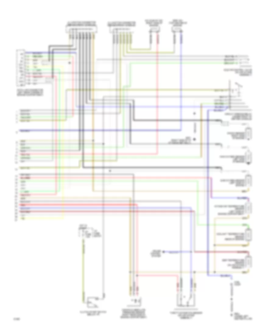
1.8L, Engine Performance Wiring Diagrams, M/T (1 of 2) for Toyota Celica ST 1994
List of elements for 1.8L, Engine Performance Wiring Diagrams, M/T (1 of 2) for Toyota Celica ST 1994:
- #10
- #20
- (behind center
- A/c amplifier
- Ac1
- Act
- B13
- Batt
- Distributor
- E01
- E02
- Efi fuse 15a
- Efi main relay (r/b #2)
- Egr
- Electronic controlled transmission ecu (a/t) engine control module (m/t) of console)
- Els
- G100 (left front fender)
- G131 (intake manifold)
- Gauge fuse 10a
- Hot at all times
- Hot in run
- Hot in start or run
- Hot with defog on
- Hot with light sw on
- I/p junction block
- Idl
- Idle-up diode
- Ig+
- Ig-
- Igf
- Ign fuse 7.5a
- Igniter
- Ignition coil
- Igt
- Injector #1
- Injector #2
- Injector #3
- Injector #4
- Instrument cluster
- Isc
- Knk
- Mal- func ind
- Mir-htr fuse 10a
- Nca
- Ne+
- Ne-
- Ox1
- Ox2
- Pim
- Pnk
- R/b #2
- Red
- Rsc
- Rso
- Spd
- Speed sensor (rear of engine)
- Speedo
- Sta
- Tail fuse 15a
- Te1
- Te2
- Tha
- Thg
- Thw
- Vta
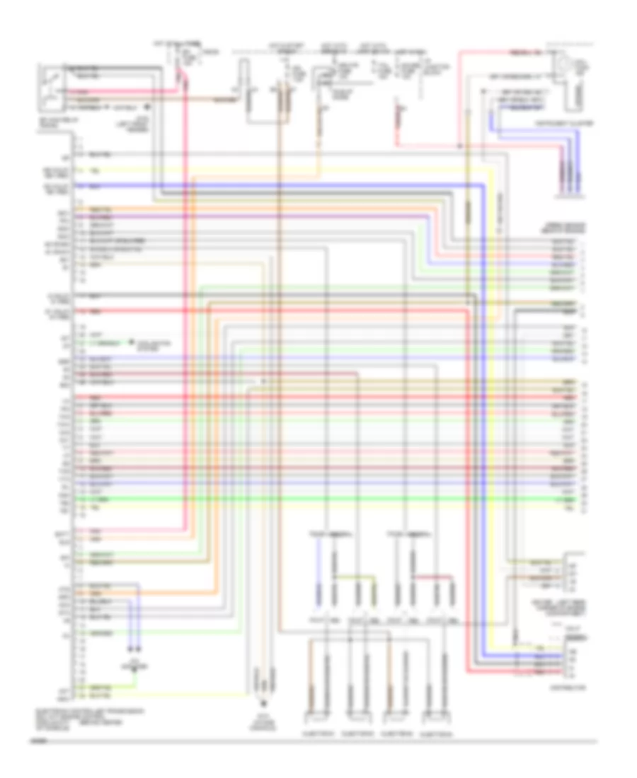
1.8L, Engine Performance Wiring Diagrams, M/T (2 of 2) for Toyota Celica ST 1994
List of elements for 1.8L, Engine Performance Wiring Diagrams, M/T (2 of 2) for Toyota Celica ST 1994:
- A/c idle-up vsv (right side of engine)
- Circuit opening relay (under front of center console)
- Clutch start switch (below i/p)
- Coolant temperature sensor (rear of engine)
- Cruise control system
- Data link connector (left rear corner of engine compartment)
- Egr temperature sensor (on air intake assembly)
- Egr vsv (top center of engine)
- Fuel pump
- G201 (right side of i/p at r/b #4 set bolt)
- G904 (under left center pillar)
- Hot in start
- I/p fuse block
- Idle air control valve (on air intake assembly)
- Ig-
- Intake air temperature sensor (left side of engine compartment)
- J3 junction connector (behind front console)
- J4 junction connector (behind front console)
- Knock sensor (right side of engine)
- Main oxygen sensor (left side of engine)
- Manifold absolute pressure sensor (right rear side of engine compartment)
- Nca
- Ox1
- Ox2
- Pim
- Red
- St fuse 7.5a
- Sub oxygen sensor (left side of engine)
- Te1
- Te2
- Throttle position sensor (on air intake assembly)
- Vf1
2.2L
2.2L, Engine Performance Wiring Diagrams (1 of 2) for Toyota Celica ST 1994
List of elements for 2.2L, Engine Performance Wiring Diagrams (1 of 2) for Toyota Celica ST 1994:
- #1 0r #10
- #2 or #20
- (behind center
- (left rear corner of engine compartment)
- A/c amplifier
- Aca
- Act
- Ats
- B/k
- B13
- Batt
- Calif
- Cooling fan system
- Distributor
- E01
- E02
- Efi fuse 15a
- Efi main relay (r/b #2)
- Egr
- Electronic controlled transmission ecu (a/t) engine control module (m/t) of console)
- Els
- Fed
- Federal
- Fpu
- G (calif) g- (fed)
- G1 (calif) g+ (fed)
- G100 (left front fender)
- G131 (intake manifold)
- G2 (calif) ne- (fed)
- Gauge fuse 10a
- Hot at all times
- Hot in run
- Hot in start or run
- Hot with defog on
- Hot with light sw on
- I/p junction block
- Idl
- Idle-up diode
- Ig-
- Igf
- Ign fuse 7.5a
- Igniter
- Igt
- Injector #1
- Injector #2
- Injector #3
- Injector #4
- Instrument cluster
- Iscc
- Isco
- Iscv
- Knk
- Mal- func ind
- Mir-htr fuse 10a
- Nca
- Ne (calif) ne+ (fed)
- Nsw
- Ox1
- Ox2
- Pim
- Pnk
- R/b #2
- Red
- Spd
- Speed sensor (rear of engine)
- Speedo
- Sta
- Tail fuse 15a
- Te1
- Te2
- Tha
- Thg
- Thw
- Vta
2.2L, Engine Performance Wiring Diagrams (2 of 2) for Toyota Celica ST 1994
List of elements for 2.2L, Engine Performance Wiring Diagrams (2 of 2) for Toyota Celica ST 1994:
- (calif)
- A/c idle-up vsv (right side of engine)
- A/t
- Circuit opening relay (under front of center console)
- Clutch start switch (below i/p)
- Coolant temperature sensor (rear of engine)
- Cruise control system
- Data link connector (left rear corner of engine compartment)
- Egr temperature sensor (on air intake assembly)
- Egr vsv (top center of engine)
- F11
- Fuel pressure-up vsv (top center of engine) (calif only)
- Fuel pump
- G201 (right side of i/p at r/b #4 set bolt)
- G904 (under left center pillar)
- Hot at all times
- Hot in start
- I/p fuse block
- Idle air control valve (on air intake assembly)
- Ig-
- Intake air temperature sensor (left side of engine compartment)
- J2 junction connector (behind left side of i/p)
- J3 junction connector (behind front console)
- J4 junction connector (behind front console)
- Knock sensor (right side of engine)
- M/t
- Manifold absolute pressure sensor (right rear side of engine compartment)
- Nca
- Ox1
- Ox2
- Oxygen sensor (federal) main oxygen sensor (left side of engine)
- P/n
- Park/neutral position switch (left side of transmission)
- Pim
- Red
- St fuse 7.5a
- Starter relay
- Stop fuse 15a
- Stop light switch (behind i/p)
- Sub oxygen sensor (left side of engine) (calif only)
- Te1
- Te2
- Throttle position sensor (on air intake assembly)
- Vf1