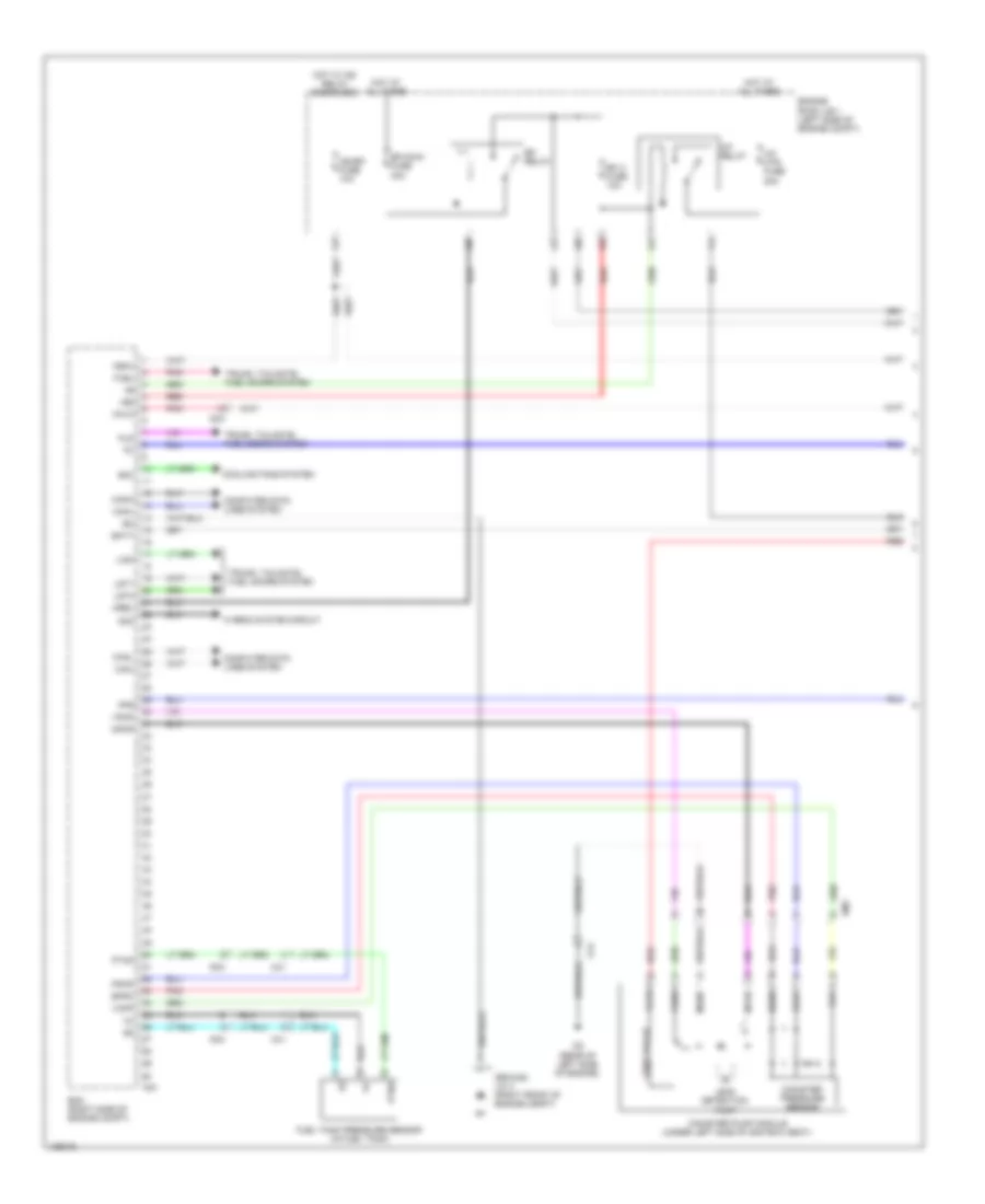
ENGINE PERFORMANCE
2.7L
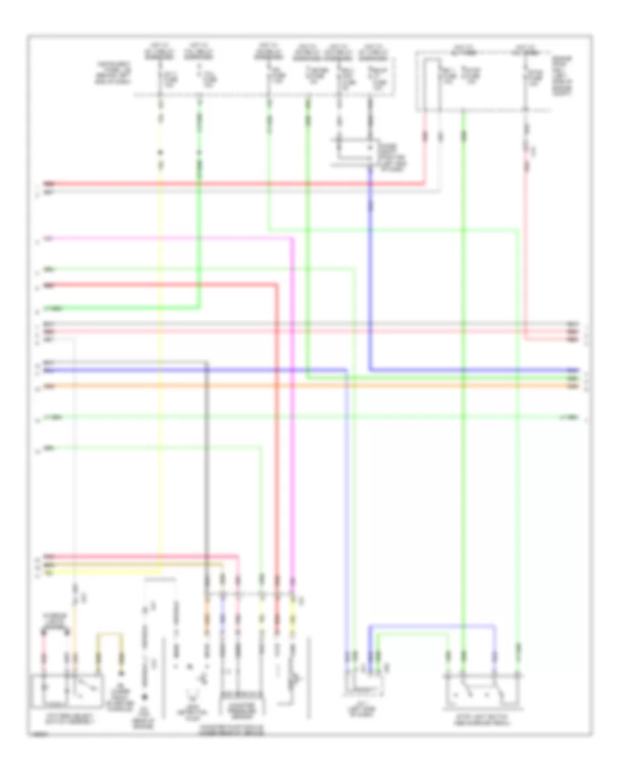
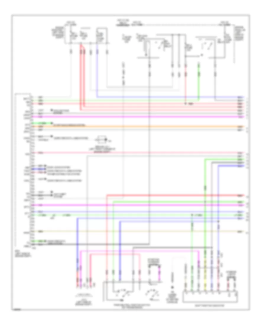
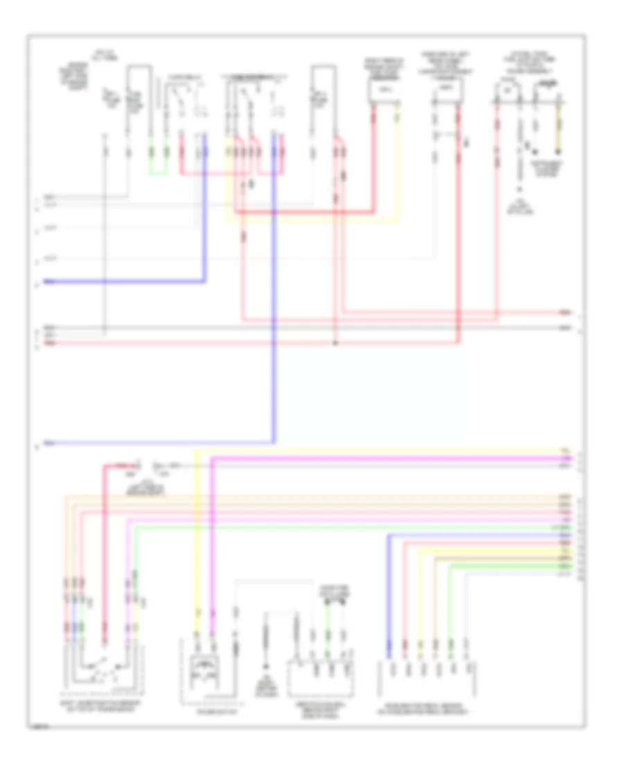
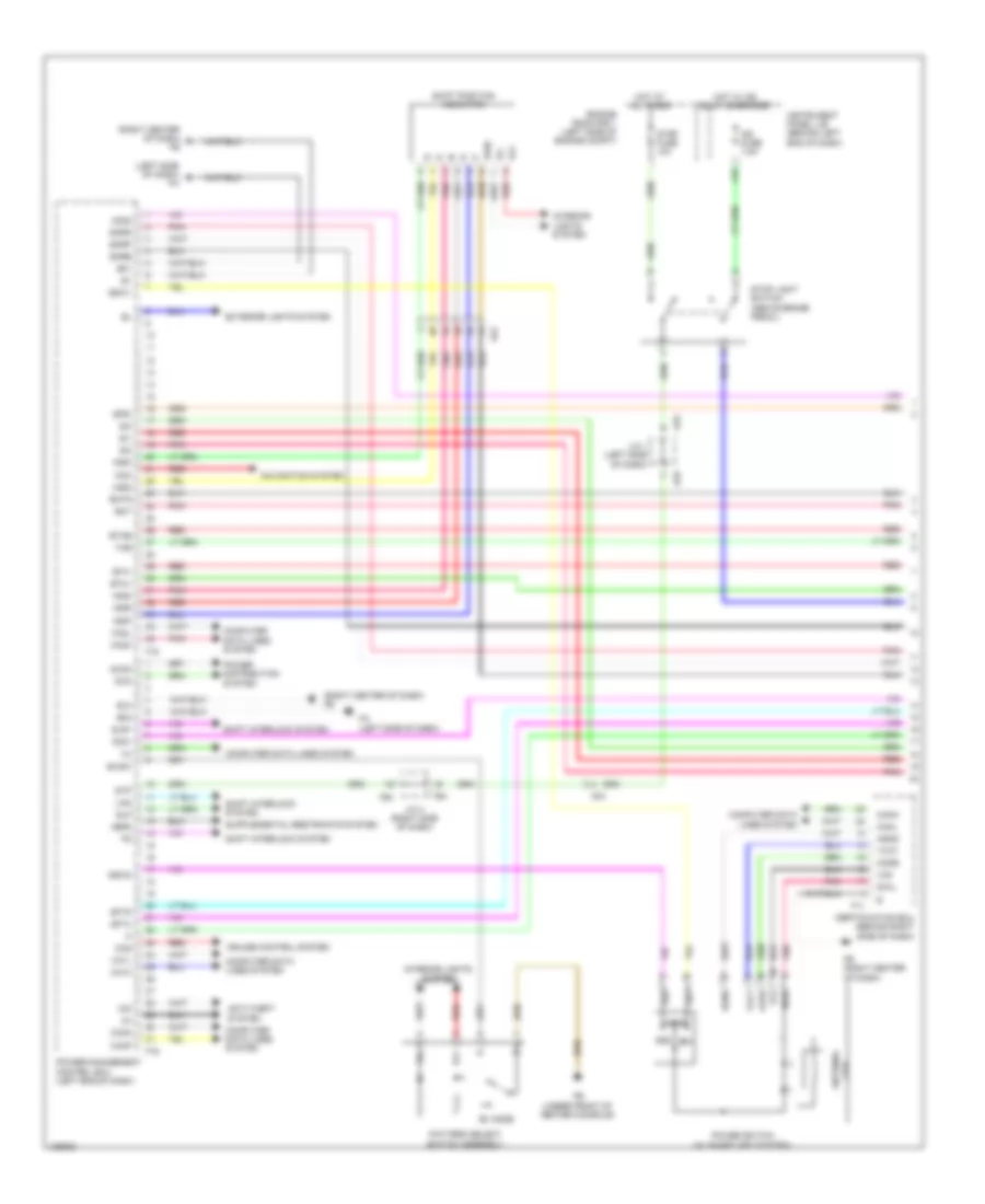
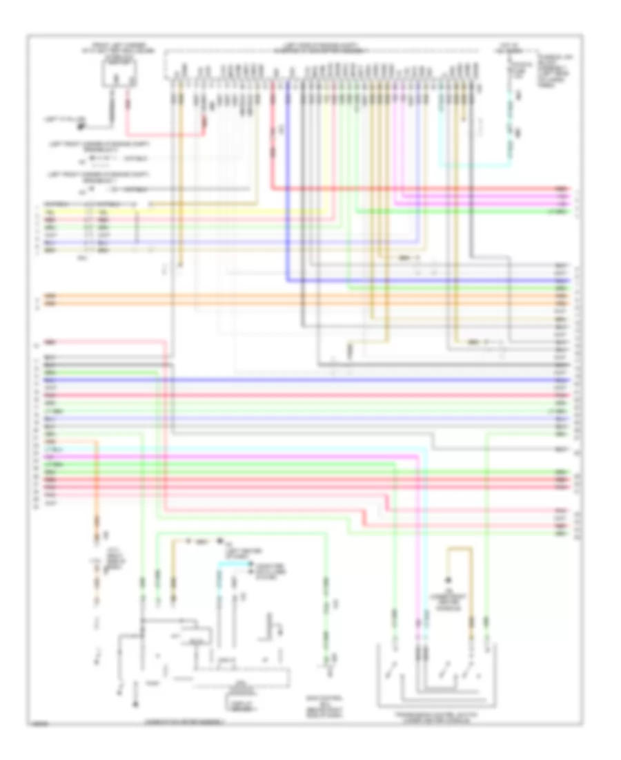
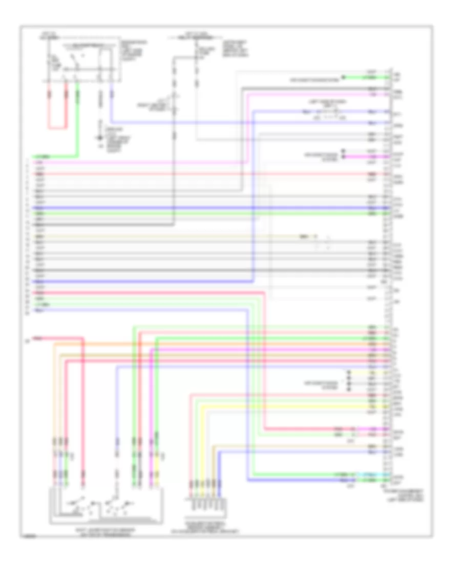
2.7L, Engine Performance Wiring Diagram (1 of 5) for Toyota Highlander LE 2014

List of elements for 2.7L, Engine Performance Wiring Diagram (1 of 5) for Toyota Highlander LE 2014:
- (left front corner of engine compt)
- +b2
- A/f htr 2 fuse 10a
- A/f htr fuse 20a
- A/f relay
- A43
- Accelerator pedal sensor assembly (on accelerator pedal bracket)
- Af3
- Am1
- Anti-theft system
- Batt
- C/opn relay
- Canh
- Canl
- Ccs
- Computer data lines system
- Cooling fans system
- Cruise control system
- Ecm (left side of engine compt)
- Efi 2 fuse 10a
- Efi 3 fuse 10a
- Efi main relay
- Efi- main fuse 30a
- Els1
- Els3
- Engine room j/b (left side of engine compt)
- Engine room r/b 1 (left side of engine compt)
- Epa
- Epa2
- Eppm
- Fb (under front of center console)
- Fuel suction tube w/ pump & gauge assembly (in fuel tank)
- Gauge
- Ground j/c 1
- Hot at all times
- Hot w/ ig2 relay energized
- Idle up fuse 7.5a
- Ig2- efi fuse 10a
- Igsw
- Imi
- Imo
- Instrument cluster system
- Ma (in left rear door)
- Mpmp
- Mrel
- Pnk
- Ppmp
- Rdef
- Red
- Rfc
- Semiconductor power integration ecu
- Sftd
- Sftu
- Snwi
- Spd
- St1-
- Sta
- Starting/charging system
- Stp
- Tach
- Transmission control switch (under center console)
- Vcp2
- Vcpa
- Vcpp
- Vpa
- Vpa2
- Vpmp
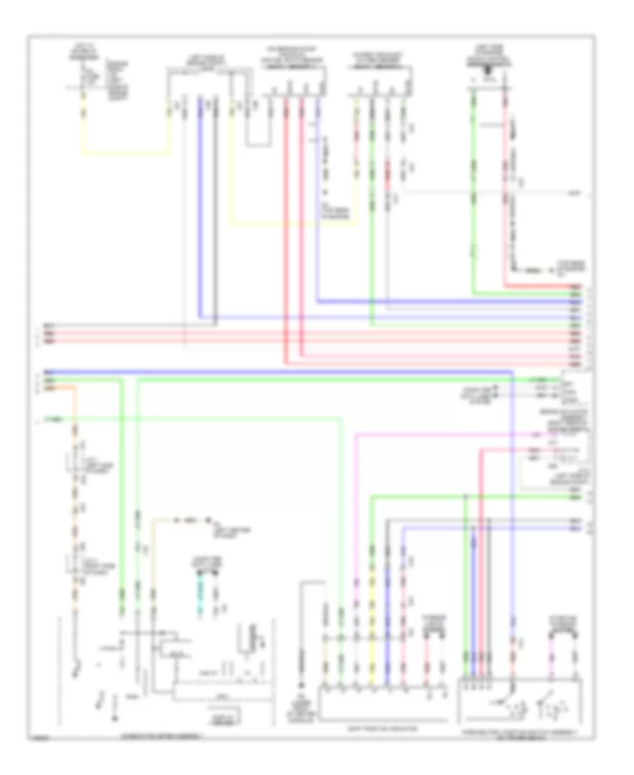
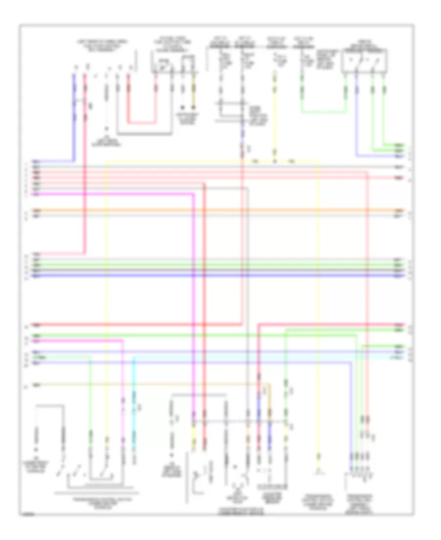
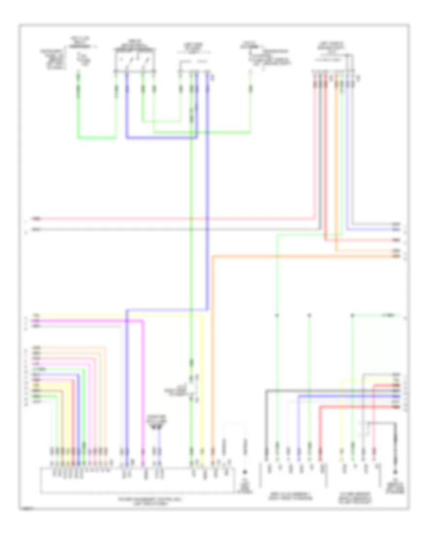
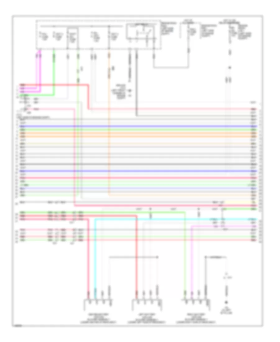
2.7L, Engine Performance Wiring Diagram (2 of 5) for Toyota Highlander LE 2014
List of elements for 2.7L, Engine Performance Wiring Diagram (2 of 5) for Toyota Highlander LE 2014:
- A51
- A53
- A70
- A71
- Af3
- Bkup lp fuse 10a
- Ca1
- Canister pressure sensor
- Canister pump module (under rear of vehicle)
- Ch (top rear of engine)
- Diode (shift position) (left end of dash)
- Ecu- acc fuse 5a
- Efi 1 fuse 10a
- Engine room r/b 1 (left side of engine compt)
- Etcs fuse 10a
- F10
- F17
- F21
- Fb (under front of center console)
- Hot at all times
- Hot w/ acc relay energized
- Hot w/ ig1 2 relay energized
- Hot w/ ig1 3 relay energized
- Hot w/ ig2 relay energized
- Hot w/ tail relay energized
- Ig1 3 fuse 10a
- Ig2 fuse 7.5a
- Instrument panel j/b (behind left end of dash)
- Interior lights system
- J/c 1 (left side of dash)
- La1
- Leak detection pump
- Meter fuse 5a
- Mgnd
- Mtrb
- Pattern select switch assembly
- Pnk
- Red
- Sgnd
- Stop fuse 10a
- Stop light switch (above brake pedal)
- Tail fuse 10a
- Vcc
- Vent valve
- Vgnd
- Vlvb
- Vout
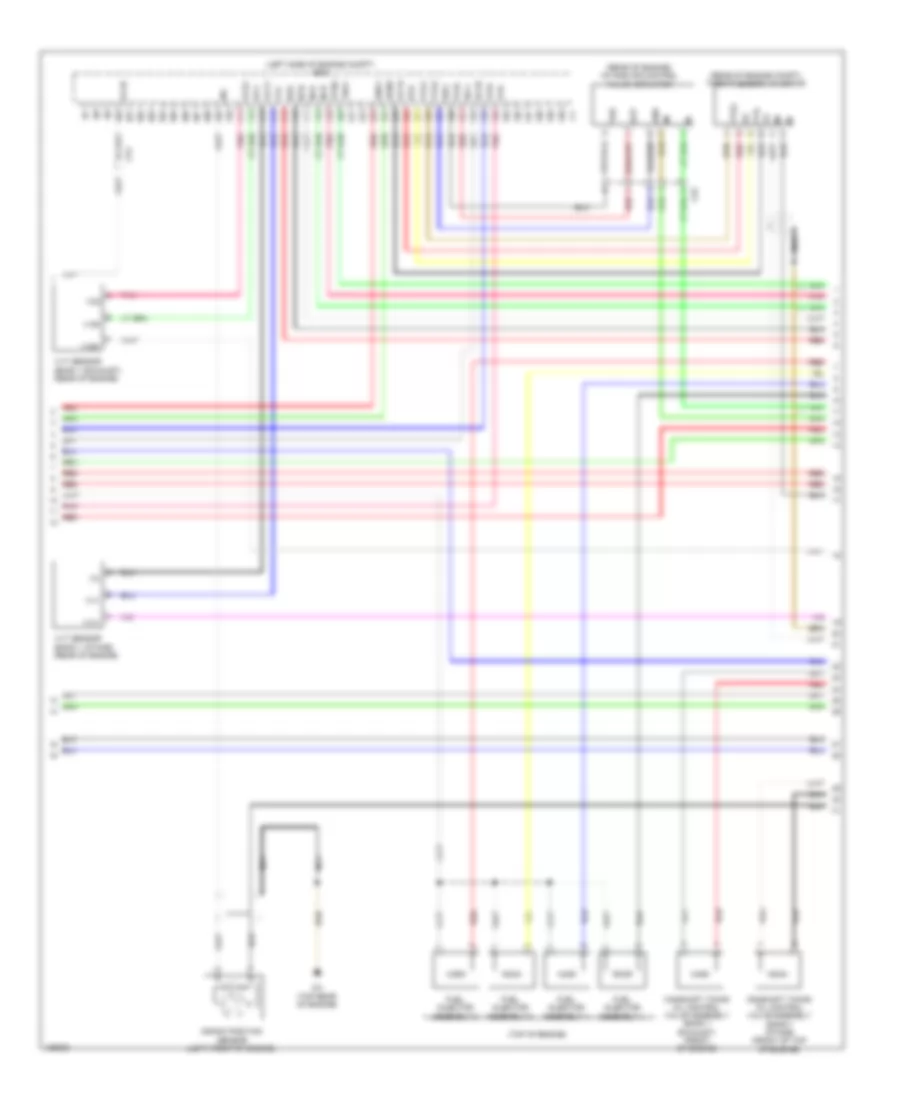
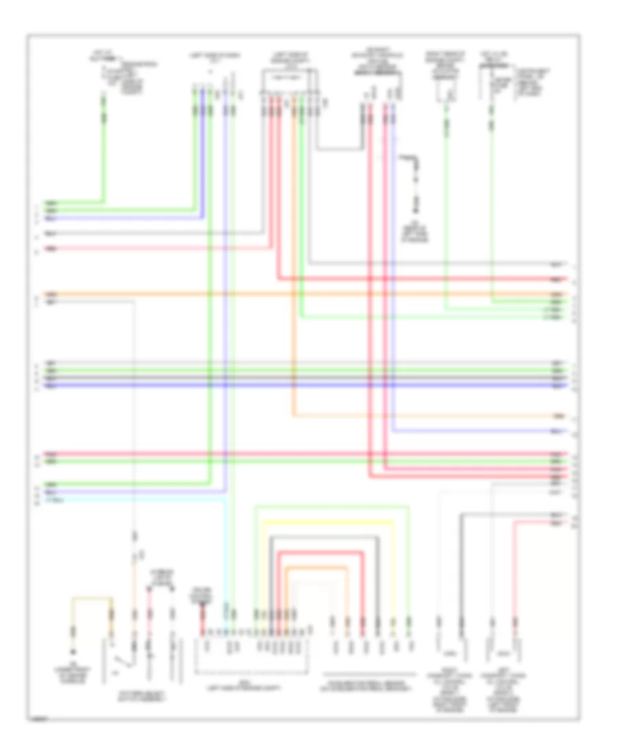
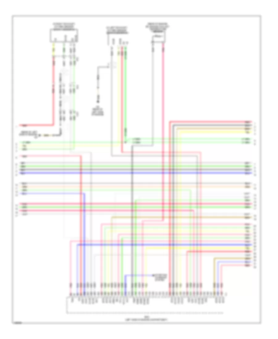
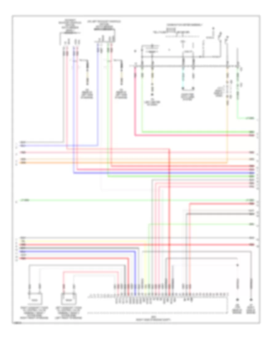
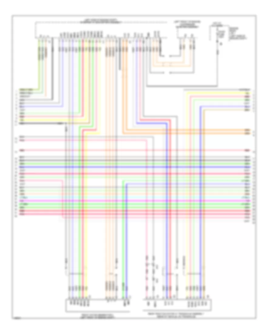
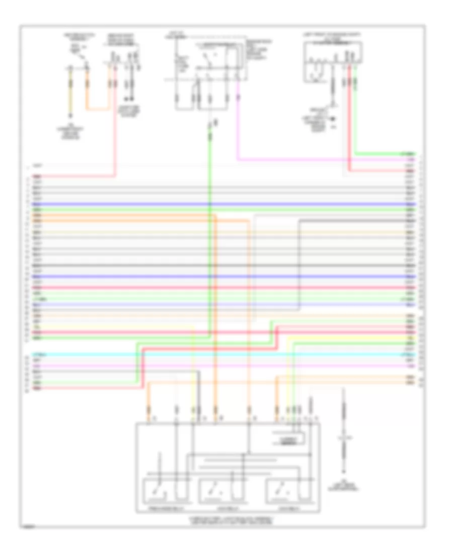
2.7L, Engine Performance Wiring Diagram (3 of 5) for Toyota Highlander LE 2014
List of elements for 2.7L, Engine Performance Wiring Diagram (3 of 5) for Toyota Highlander LE 2014:
- (in right exhaust) oxygen sensor (bank 1 sensor 2)
- (left side of engine compt) j/c 2
- (left side of engine) knock control sensor (bank 1)
- (on rear exhaust manifold) air fuel ratio sensor (bank 1 sensor 1)
- (top rear of engine) ch
- 5v ic
- A1a+
- A1a-
- A70
- A71
- A77
- Af2
- Af3
- Af4
- Brake actuator assembly (right rear of engine compt)
- C58
- Ca1
- Ca2
- Can i/f
- Canh
- Canl
- Ch (top rear of engine)
- Combination meter assembly
- Computer data lines system
- Cpu
- Cz2
- Display driver
- Engine room j/b (left side of engine compt)
- F22
- F95
- Fa2
- Fb (under front of center console)
- Fd (left center of dash)
- Fp2
- Fq1
- Ha1a
- Hot w/ ig2 relay energized
- Ht1b
- I/f
- Ill+
- Ill-
- Inj fuse 15a
- Interior lights system
- J/c 1 (left side of dash)
- J/c 2 (left side of engine compt)
- J/c 4 (right side of dash)
- Nca
- Ox1b
- Park/neutral position switch assembly (on transmission)
- Pnk
- Red
- Shift position indicator
- Sp1
- Speaker
- Starting/ charging system
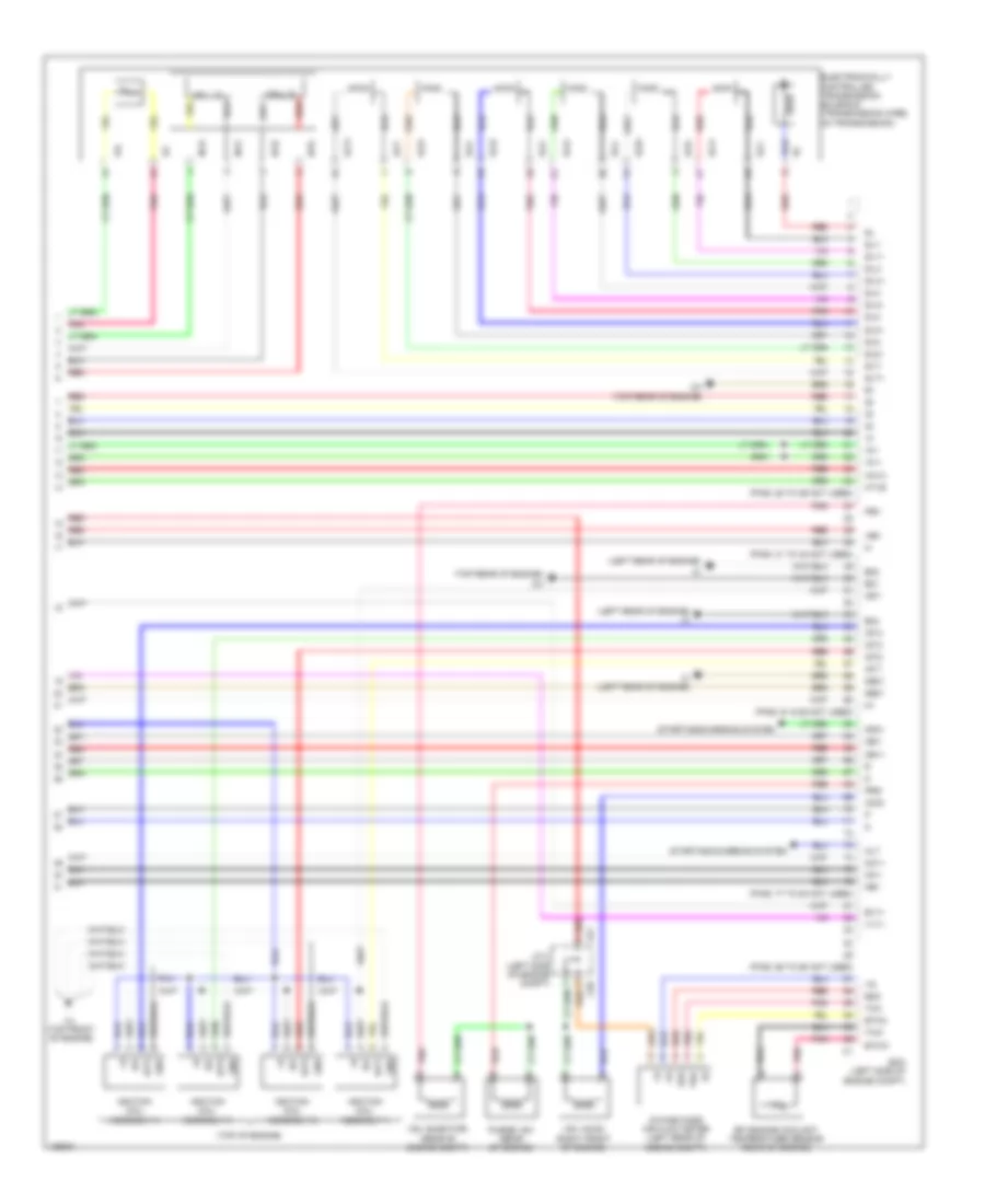
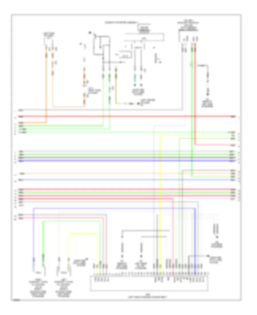
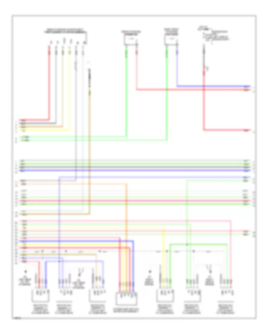
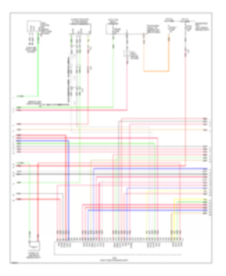
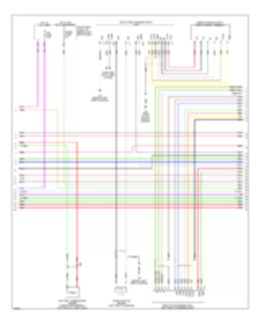
2.7L, Engine Performance Wiring Diagram (4 of 5) for Toyota Highlander LE 2014
List of elements for 2.7L, Engine Performance Wiring Diagram (4 of 5) for Toyota Highlander LE 2014:
- (left side of engine compt) ecm
- (rear of engine compt) throttle body w/ motor
- (rear of engine) intake air control valve actuator
- (top of engine)
- A1a+
- A1a-
- Ca1
- Camshaft timing oil control valve assembly (bank 1 exhaust) (front of engine)
- Camshaft timing oil control valve assembly (bank 1 intake) (front of top of engine)
- Ch (top rear of engine)
- Crank position sensor (left front of engine)
- Cz2
- Eia1
- Eknk
- Eta
- Etho
- Ev1-
- Ex1b
- Fuel injector assembly 1
- Fuel injector assembly 2
- Fuel injector assembly 3
- Fuel injector assembly 4
- Gnd
- Iac1
- Knk1
- Nca
- Ncb
- Nco
- Ne-
- Ntb
- Nto
- Out
- Ox1b
- Pnk
- Red
- Tho1
- Vc2
- Vce1
- Vcia
- Vcta
- Vcv1
- Vdd
- Vta
- Vta1
- Vta2
- Vve+
- Vve-
- Vvi+
- Vvi-
- Vvt sensor (bank 1 exhaust) (rear of engine)
- Vvt sensor (bank 1 intake) (rear of engine)
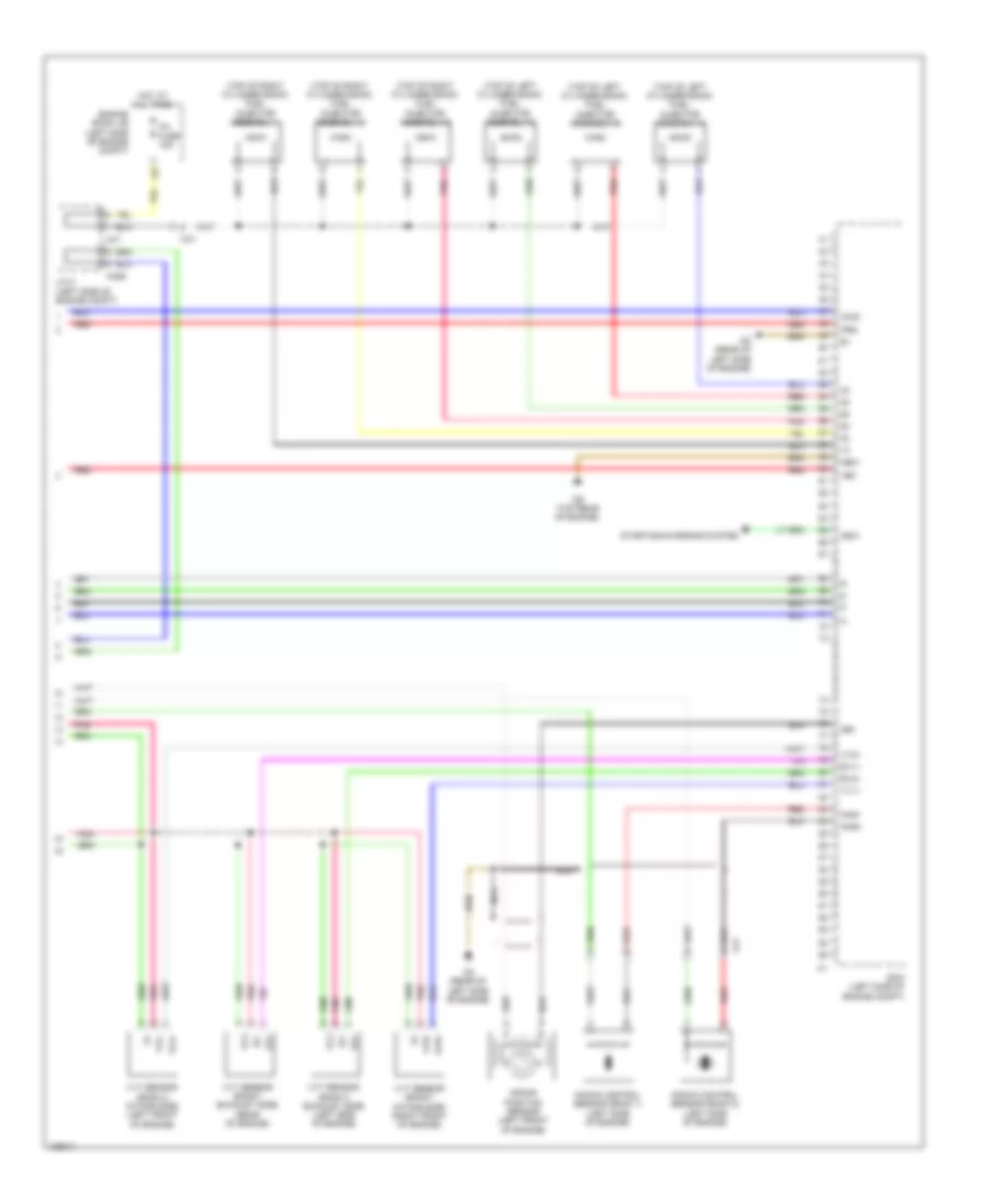
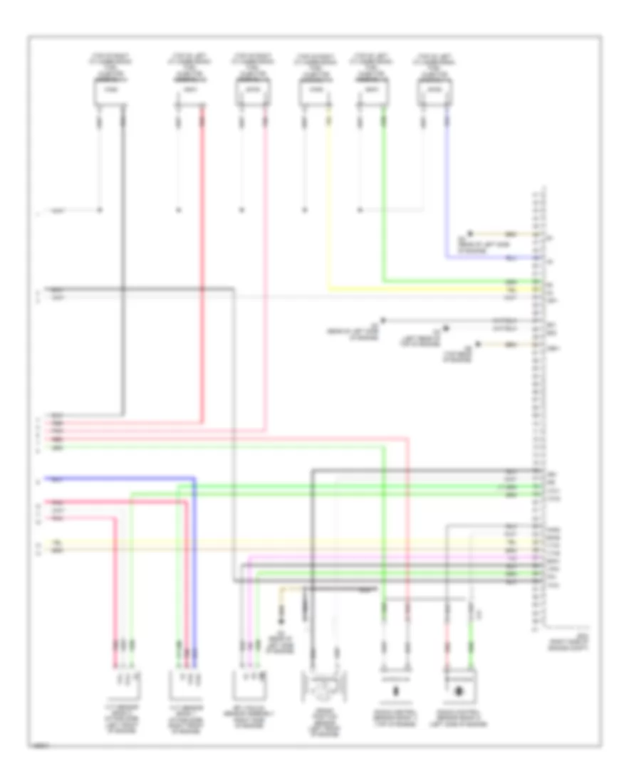
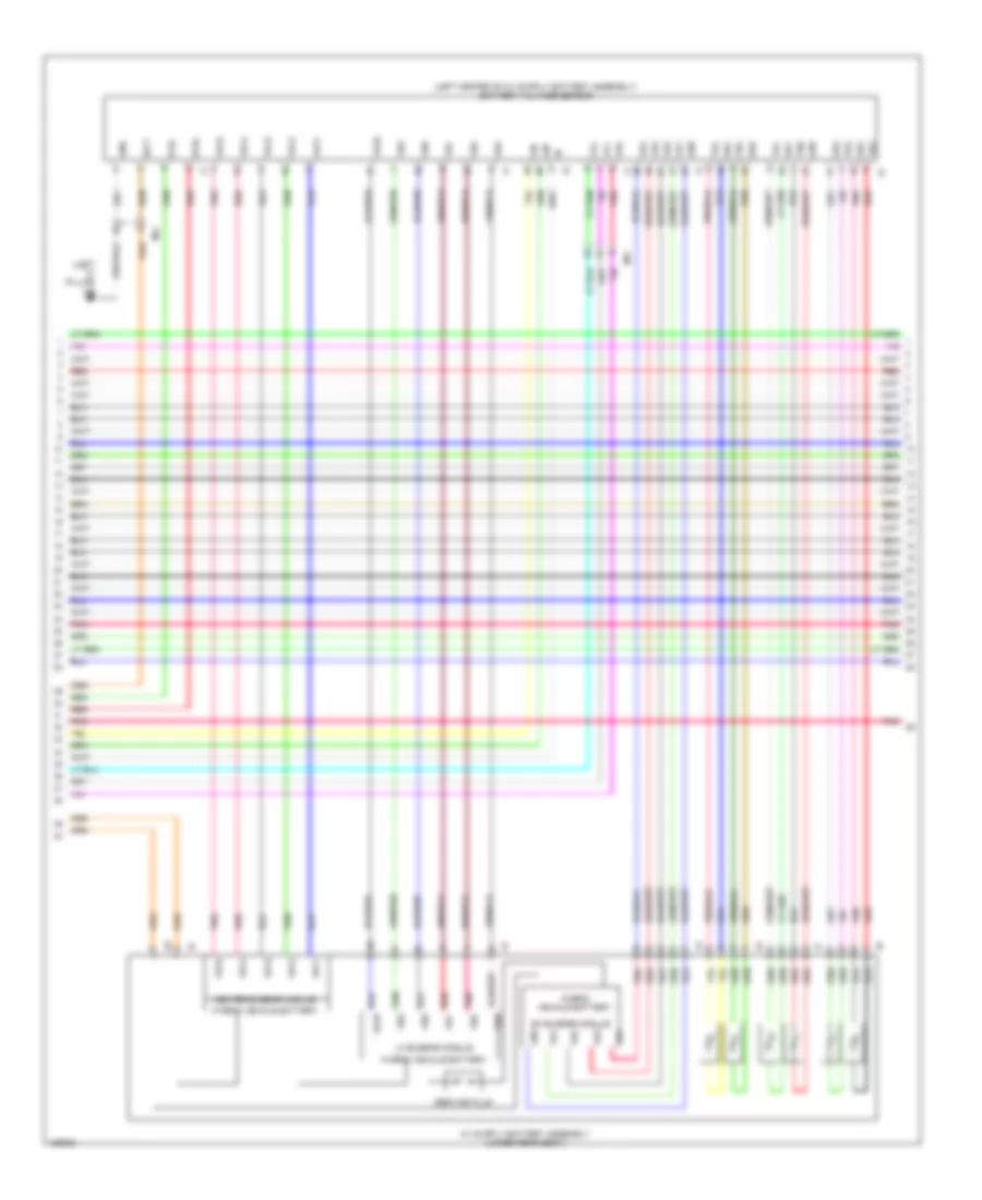
2.7L, Engine Performance Wiring Diagram (5 of 5) for Toyota Highlander LE 2014
List of elements for 2.7L, Engine Performance Wiring Diagram (5 of 5) for Toyota Highlander LE 2014:
- (left rear of engine)
- (left rear of engine) ci
- (pins: 25 to 26 not used)
- (pins: 31 to 48 not used)
- (pins: 61 & 62 not used)
- (pins: 77 to 80 not used)
- (pins: 86 to 90 not used)
- (top front of engine)
- (top of engine)
- (top rear of engine)
- +bm
- A77
- Acis
- Alt
- C58
- Ch (top rear of engine)
- Ci (left rear of engine)
- E01
- E02
- E04
- E2g
- Ecm (left side of engine compt)
- Efi engine coolant temperature sensor (rear of engine)
- Electronically controlled transmission solenoid (transmission wire) (in transmission)
- Etha
- Ethw
- Ev1+
- Ge01
- Gnd
- Ha1a
- Hall ic
- Ht1b
- Ia1+
- Ia1-
- Igf
- Igf1
- Ignition coil assembly 1
- Ignition coil assembly 2
- Ignition coil assembly 3
- Ignition coil assembly 4
- Igt1
- Igt2
- Igt3
- Igt4
- Intake mass air flow meter (left rear of engine compt)
- J/c 2 (left side of engine compt)
- Me01
- Ncb
- Nco
- Ne+
- Nsw
- Ntb
- Nto
- Oc1+
- Oc1-
- Oe1+
- Oe1-
- Oil
- Pbv
- Pnk
- Prg
- Purge vsv (rear of engine)
- Red
- Sl1+
- Sl1-
- Sl2+
- Sl2-
- Sl3+
- Sl3-
- Sl4+
- Sl4-
- Slt+
- Slt-
- Slu+
- Slu-
- Starting/charging system
- Tha
- Thw
- Vsv (acis) (right front of engine)
- Vsv (ejector) (rear of engine compt)
- Vv1+
3.5L
3.5L, Engine Performance Wiring Diagram (1 of 7) for Toyota Highlander LE 2014
List of elements for 3.5L, Engine Performance Wiring Diagram (1 of 7) for Toyota Highlander LE 2014:
- +b2
- A/f htr fuse 20a
- A/f relay
- A43
- A77
- Af3
- Anti-theft system
- Batt
- C58
- Ca2
- Canh
- Canl
- Computer data lines system
- Cooling fans system
- Door locks system
- Ecm (left side of engine compt)
- Efi 1 fuse 10a
- Efi 2 fuse 10a
- Efi 3 fuse 10a
- Efi main fuse 30a
- Efi main relay
- Els2
- Engine room j/b (left side of engine compt)
- Engine room r/b 1 (left side of engine compt)
- Fb (under front of center console)
- Fpc
- Fq1
- Fuel pmp fuse 10a
- Ground j/c 1 (left front corner of engine compt)
- Hot at all times
- Hot w/ ig2 relay energized
- Ig2 efi fuse 10a
- Igsw
- Ill+
- Ill-
- Imi
- Imo
- Interior lights system
- J/c 2 (left side of engine compt)
- Mpmp
- Mrel
- Neo
- Park/neutral position switch (on transmission)
- Pnk
- Power distribution system
- Ppmp
- Red
- Rfc
- Sftu
- Shift position indicator
- Snwi
- Spd
- St1-
- Sta
- Starting/ charging system
- Starting/charging system
- Tach
- Vpmp
3.5L, Engine Performance Wiring Diagram (2 of 7) for Toyota Highlander LE 2014
List of elements for 3.5L, Engine Performance Wiring Diagram (2 of 7) for Toyota Highlander LE 2014:
- (above brake pedal) stop light switch
- (in fuel tank) fuel suction tube w/ pump & gauge assembly
- (left rear of cargo area) fuel pump control ecu assembly
- (under front of center console)
- A51
- Af3
- Am1
- Bkup lp fuse 10a
- Ca1
- Ca2
- Canister pressure sensor
- Canister pump module (under rear of vehicle)
- Cd (rear of left side of engine)
- Diode (shift position) (left end of dash)
- Ecu- acc fuse 5a
- F10
- F17
- F21
- Fp-
- Fpc
- Gauge
- Hot w/ acc relay energized
- Hot w/ ig1 2 relay energized
- Hot w/ ig1 3 relay energized
- Hot w/ ig2 relay energized
- Ig1 3 fuse 10a
- Ig2 fuse 7.5a
- Instrument cluster system
- Instrument panel j/b (behind left end of dash)
- La1
- Leak detection pump
- Mc (left rear quarterpanel)
- Mgnd
- Mtrb
- Pnk
- Pump
- Red
- Sftd
- Sftu
- Sgnd
- Stp
- Transmission control ecu assembly (left front engine compt)
- Transmission control switch (under center console)
- Vcc
- Vent valve
- Vout
3.5L, Engine Performance Wiring Diagram (3 of 7) for Toyota Highlander LE 2014
List of elements for 3.5L, Engine Performance Wiring Diagram (3 of 7) for Toyota Highlander LE 2014:
- (left side of dash) j/c 1
- (left side of engine compt) j/c 2
- (on right exhaust manifold) air fuel ratio sensor (bank 1 sensor 1)
- (right rear of engine compt) brake actuator assembly
- 2nd
- A1a+
- A1a-
- A43
- A53
- A70
- A71
- A77
- Accelerator pedal sensor (on accelerator pedal bracket)
- Af3
- C58
- Ccs
- Cd (rear of left side of engine)
- Cruise control system
- Ecm (left side of engine compt)
- Engine room r/b 1 (left side of engine compt)
- Epa
- Epa2
- F10
- Fb (under front of center console)
- Ha1a
- Hot at all times
- Hot w/ ig2 relay energized
- Ill+
- Ill-
- Instrument panel j/b (behind left end of dash)
- Interior lights system
- Left camshaft timing oil control valve (bank 2 intake side) (left front of engine)
- Meter fuse 5a
- Nca
- Pattern select switch assembly
- Pnk
- Red
- Right camshaft timing oil control valve (bank 1 intake side) (right front of engine)
- Sftd
- Sp1
- Stop fuse 10a
- Stp
- Vcp2
- Vcpa
- Vpa
- Vpa2
3.5L, Engine Performance Wiring Diagram (4 of 7) for Toyota Highlander LE 2014
List of elements for 3.5L, Engine Performance Wiring Diagram (4 of 7) for Toyota Highlander LE 2014:
- (left center of dash) fd
- (left side of dash) j/c 1
- (on left exhaust manifold) air fuel ratio sensor (bank 2 sensor 1)
- 5v ic
- A2a+
- A2a-
- A70
- A71
- Af2
- Can i/f
- Can+
- Can-
- Cd (rear of left side of engine)
- Ce (top rear of engine)
- Cg (left rear of top of engine)
- Combination meter assembly
- Computer data lines system
- Cpu
- Driver display
- E02
- E04
- E05
- Ecm (left side of engine compartment)
- F22
- F95
- Fa2
- Ha1a
- Ha2a
- Ht1b
- Ht2b
- I/f
- J/c 4 (right side of dash)
- Left camshaft timing oil control valve (bank 2 exhaust side) (left front of engine)
- Nca
- Oc1+
- Oc1-
- Oc2+
- Oc2-
- Oe1+
- Oe1-
- Oe2+
- Oe2-
- Pnk
- Red
- Right camshaft timing oil control valve (bank 1 exhaust side) (right front of engine)
- Speaker
3.5L, Engine Performance Wiring Diagram (5 of 7) for Toyota Highlander LE 2014
List of elements for 3.5L, Engine Performance Wiring Diagram (5 of 7) for Toyota Highlander LE 2014:
- (in left exhaust) oxygen sensor (bank 2 sensor 2)
- (in right exhaust)
- (rear of engine) efi engine coolant temperature sensor
- (rear of left side of engine) cd
- A1a+
- A1a-
- A2a+
- A2a-
- Af4
- Alt
- Ca1
- Cd (rear of left side of engine)
- E2g
- Ecm (left side of engine compartment)
- Ekn2
- Eknk
- Eta
- Etha
- Ethw
- Ex1b
- Ex2b
- Fp2
- Ge01
- Ht1b
- Ht2b
- Igf1
- Igt1
- Igt2
- Igt3
- Igt4
- Igt5
- Igt6
- Nca
- Ne-
- Ox1b
- Ox2b
- Oxygen sensor (bank 1 sensor 2)
- Pnk
- Red
- Starting/ charging system
- Tha
- Thw
- Vcta
- Vcv1-
- Vta1
- Vta2
- Vv1-
3.5L, Engine Performance Wiring Diagram (6 of 7) for Toyota Highlander LE 2014
List of elements for 3.5L, Engine Performance Wiring Diagram (6 of 7) for Toyota Highlander LE 2014:
- (rear of engine compartment) throttle body w/ motor assembly
- (rear of engine) purge vsv
- (right front of engine) vsv (acis)
- Ca1
- Cf (right side of engine)
- Cg (left rear of top of engine)
- E2g
- Engine room r/b 1 (left side of engine compt)
- Etcs fuse 10a
- Gnd
- Hot at all times
- Igf
- Ignition coil assembly 1 (top of right cylinder bank)
- Ignition coil assembly 2 (top of left cylinder bank)
- Ignition coil assembly 3 (top of right cylinder bank)
- Ignition coil assembly 4 (top of left cylinder bank)
- Ignition coil assembly 5 (top of right cylinder bank)
- Ignition coil assembly 6 (top of left cylinder bank)
- Igt1
- Igt2
- Igt3
- Igt4
- Igt5
- Igt6
- Intake mass air flow meter sub-assembly
- Nca
- Pnk
- Red
- Tha
- Vta
- Vta2
3.5L, Engine Performance Wiring Diagram (7 of 7) for Toyota Highlander LE 2014
List of elements for 3.5L, Engine Performance Wiring Diagram (7 of 7) for Toyota Highlander LE 2014:
- (top of left cylinder bank) fuel injector assembly 2
- (top of left cylinder bank) fuel injector assembly 4
- (top of left cylinder bank) fuel injector assembly 6
- (top of right cylinder bank) fuel injector assembly 1
- (top of right cylinder bank) fuel injector assembly 3
- (top of right cylinder bank) fuel injector assembly 5
- +bm
- A77
- Ac58
- Acis
- Ca1
- Cd (rear of left side of engine)
- Ce (top rear of engine)
- Crank position sensor (left front of engine)
- Cz1
- Ecm (left side of engine compt)
- Engine room j/b (left side of engine compt)
- Ev1+
- Ev2+
- Ex+
- Ex-
- Hot at all times
- Inj fuse 15a
- J/c 2 (left side of engine compt)
- Knk1
- Knk2
- Knock control sensor (bank 1) (left side of engine)
- Knock control sensor (bank 2) (left side of engine)
- Me01
- Nca
- Ne+
- Nsw
- Pnk
- Prg
- Red
- Starting/charging system
- Vc2
- Vv1+
- Vv2+
- Vvl+
- Vvl-
- Vvr+
- Vvr-
- Vvt sensor (bank 2 exhaust side) (left side of engine)
- Vvt sensor (bank 2 intake side) (left front of engine)
- Vvt sensor (bank1 exhaust side) (rear of engine)
- Vvt sensor (bank1 intake side) (right front of engine)
3.5L HYBRID
3.5L Hybrid, Engine Controls Wiring Diagram (1 of 7) for Toyota Highlander LE 2014
List of elements for 3.5L Hybrid, Engine Controls Wiring Diagram (1 of 7) for Toyota Highlander LE 2014:
- +b2
- A/f htr fuse 20a
- A/f relay
- A43
- Am3
- Batt
- Ca1
- Can+
- Can-
- Canh
- Canister pressure sensor
- Canister pump module (under left side of 2nd row seat)
- Canl
- Ccv2
- Cd (rear of left side of engine)
- Computer data lines system
- Cooling fans system
- Ecm (right side of engine compt)
- Efi 2 fuse 10a
- Efi relay
- Efi-main fuse 30a
- Engine room j/b 1 (left side of engine compt)
- Eppm
- Fpr
- Fuel
- Fuel tank pressure sensor (in fuel tank)
- Fuo
- Go2
- Ground j/c 4 (right front of engine compt)
- Hot at all times
- Hot w/ ig2 relay energized
- Hybrid system circuit
- Ig2-efi fuse 10a
- Igsw
- Leak detection pump
- Lido
- Lst1
- Lst2
- Mgnd
- Mpmp
- Mrel
- Mtrb
- Mc1
- Pnk
- Ppmp
- Ptnk
- Red
- Rfc
- Sgnd
- Trunk, tailgate, fuel doors system
- Vcc
- Vcpp
- Vent valve
- Vgnd
- Vlvb
- Vout
- Vpmp
3.5L Hybrid, Engine Controls Wiring Diagram (2 of 7) for Toyota Highlander LE 2014
List of elements for 3.5L Hybrid, Engine Controls Wiring Diagram (2 of 7) for Toyota Highlander LE 2014:
- (forward of left rear wheel) vsv (fuel vapor-containment valve)
- (in fuel tank) fuel suction tube w/ pump & gauge assembly
- (right rear of engine compt) fuel pump resistor
- A78
- Accelerator pedal sensor (on accelerator pedal bracket)
- Agnd
- Am1
- Am3
- C/opn relay
- C59
- Ca2
- Canh
- Canl
- Certification ecu (behind right side of dash)
- Computer data lines system
- Efi 1 fuse 10a
- Efi 3 fuse 10a
- Engine room r/b 1 (left side of engine compt)
- Epa
- Epa2
- F11
- Fe (right center of dash)
- Fuel pmp fuse 10a
- Fuel pmp relay
- Gauge
- Hot at all times
- Instrument cluster system
- J/c 2 (left side of engine compt)
- Ma (in left "b" pillar)
- Mc1
- Pnk
- Power switch
- Pump
- Red
- Shift lever position sensor (on top of transmission)
- Ss1
- Ss2
- Vcp2
- Vcpa
- Vpa
- Vpa2
- Cm1
3.5L Hybrid, Engine Controls Wiring Diagram (3 of 7) for Toyota Highlander LE 2014
List of elements for 3.5L Hybrid, Engine Controls Wiring Diagram (3 of 7) for Toyota Highlander LE 2014:
- (above brake pedal) stop light switch
- (left side of dash) j/c 1
- (left side of engine compt) j/c 2
- +b1
- +b2
- A60
- A61
- A70
- A78
- Af4
- C59
- Ca1h
- Ca1l
- Cd (rear of left side of engine)
- Computer data lines system
- E02
- Egr valve assembly (right front of engine)
- Egr1
- Egr2
- Egr3
- Egr4
- Engine room r/b 1 (left side of engine compt)
- Epa
- Epa2
- F10
- F15
- F16
- F94
- Fa (left side of dash)
- Hot at all times
- Hot w/ ig2 relay energized
- Ht2b
- Ig2 fuse 7.5a
- Instrument panel j/b (behind left end of dash)
- J/c 4 (right side of dash)
- Nca
- Ox2b
- Oxygen sensor (bank 2 sensor 2) (in left exhaust)
- Pnk
- Power management control ecu (left end of dash)
- Psft
- Red
- Spdi
- Ssw1
- Ssw2
- St1-
- Stop fuse 10a
- Stp
- Vcp2
- Vcpa
- Vpa
- Vpa2
3.5L Hybrid, Engine Controls Wiring Diagram (4 of 7) for Toyota Highlander LE 2014
List of elements for 3.5L Hybrid, Engine Controls Wiring Diagram (4 of 7) for Toyota Highlander LE 2014:
- (on left exhaust manifold) air fuel ratio sensor (bank 2 sensor 1)
- (on right exhaust manifold) air fuel ratio sensor (bank 1 sensor 1)
- +bm
- 5v ic
- A1a+
- A1a-
- A2a+
- A2a-
- Can i/f
- Canh
- Canl
- Cd (rear of left side of engine)
- Ce (top rear of engine)
- Cf (right side of engine)
- Combination meter assembly
- Computer data lines system
- Cpu
- E03
- E04
- E05
- Ecm (right side of engine compt)
- Egr1
- Egr2
- Egr3
- Egr4
- F22
- F95
- Fa2
- Fd (left center of dash)
- Ha1a
- Ha2a
- Ht1b
- Ht2b
- Ig+
- J/c 4 (right side of dash)
- Led driver
- Left camshaft timing oil control valve assembly (bank 2 intake side) (left front of engine)
- Nca
- Oc1+
- Oc1-
- Oc2+
- Oc2-
- Pnk
- Red
- Right camshaft timing oil control valve assembly (bank 1 intake side) (right front of engine)
- Telltales
3.5L Hybrid, Engine Controls Wiring Diagram (5 of 7) for Toyota Highlander LE 2014
List of elements for 3.5L Hybrid, Engine Controls Wiring Diagram (5 of 7) for Toyota Highlander LE 2014:
- (in right exhaust)
- (rear of left side of engine) cd
- A1a+
- A1a-
- A2a+
- A2a-
- A48
- A53
- Ca1
- Ca1h
- Ca1l
- Computer data lines system
- E2g
- Ecm (right side of engine compt)
- Eknk
- Engine room r/b 1 (left side of engine compt)
- Eta
- Etcs fuse 10a
- Etha
- Ethw
- Ex1b
- Ex2b
- F32
- Fa2
- Fp1
- Ge01
- Hot at all times
- Hot w/ ig2 relay energized
- Ht1b
- Igt1
- Igt2
- Igt3
- Igt4
- Igt5
- Igt6
- Instrument panel j/b (behind left end of dash)
- J/c 7 (right center of dash)
- Knk1
- Meter fuse 5a
- Mpx-b 1 fuse 5a
- Nca
- Ox1b
- Ox2b
- Oxygen sensor (bank 1 sensor 2)
- Pnk
- Prg
- Purge vsv (center of engine compt)
- Red
- Skid control ecu (behind right side of dash) a63
- Sp1
- Tha
- Vcta
- Vv1+
- Vv1-
- Vv2+
- Vv2-
3.5L Hybrid, Engine Controls Wiring Diagram (6 of 7) for Toyota Highlander LE 2014
List of elements for 3.5L Hybrid, Engine Controls Wiring Diagram (6 of 7) for Toyota Highlander LE 2014:
- (left side of engine compt) j/c 2
- (rear of engine compt) throttle body w/ motor assembly
- (rear of engine) efi engine coolant temperature sensor
- (top of left cylinder bank)
- (top of right cylinder bank)
- A78
- C59
- Ca1
- Cd (rear of left side of engine)
- Cf (right side of engine)
- Cg (left rear of top of engine)
- E2g
- Engine room j/b 1 (left side of engine compt)
- Gnd
- Hot w/ ig2 relay energized
- Igf
- Ignition coil assembly 1
- Ignition coil assembly 2
- Ignition coil assembly 3
- Ignition coil assembly 4
- Ignition coil assembly 5
- Ignition coil assembly 6
- Igt1
- Igt2
- Igt3
- Igt4
- Igt5
- Igt6
- Inj fuse 15a
- Intake mass air flow meter sub-assembly (left rear of engine compt)
- Nca
- Pnk
- Red
- Tha
- Vta
- Vta2
3.5L Hybrid, Engine Controls Wiring Diagram (7 of 7) for Toyota Highlander LE 2014
List of elements for 3.5L Hybrid, Engine Controls Wiring Diagram (7 of 7) for Toyota Highlander LE 2014:
- (top of left cylinder bank) fuel injector assembly 2
- (top of left cylinder bank) fuel injector assembly 4
- (top of left cylinder bank) fuel injector assembly 6
- (top of right cylinder bank) fuel injector assembly 1
- (top of right cylinder bank) fuel injector assembly 3
- (top of right cylinder bank) fuel injector assembly 5
- Cd (rear of left side of engine)
- Ce (top rear of engine)
- Cg (left rear of top of engine)
- Crank position sensor (left front of engine)
- Cz1
- E01
- E02
- Ecm (right side of engine compt)
- Efi vacuum sensor assembly (right side of engine)
- Ekn2
- Epim
- Igf1
- Knk2
- Knock control sensor (bank 1) (top of engine)
- Knock control sensor (bank 2) (left side of engine)
- Me01
- Nca
- Ne+
- Ne-
- Pim
- Pnk
- Red
- Thw
- Vcv1
- Vcv2
- Vpim
- Vta1
- Vta2
- Vvl+
- Vvl-
- Vvr+
- Vvr-
- Vvt sensor (bank 1 intake side) (right front of engine)
- Vvt sensor (bank 2 intake side) (left front of engine)
3.5L Hybrid, Hybrid System Wiring Diagram (1 of 8) for Toyota Highlander LE 2014
List of elements for 3.5L Hybrid, Hybrid System Wiring Diagram (1 of 8) for Toyota Highlander LE 2014:
- (left side of dash) fa
- (right center of dash) fe
- A70
- Abfs
- Accd
- Af4
- Agnd
- Am21
- Am22
- Anti-theft system
- Bth+
- Bth-
- Ca1h
- Ca1l
- Ca2h
- Ca2l
- Ca3n
- Ca3p
- Canh
- Canl
- Ccs
- Certification ecu (behind right side of dash)
- Code
- Coil antenna
- Computer data lines system
- Cruise control system
- E01
- E02
- E12
- Engine room r/b 1 (left side of engine compt)
- Ethb
- Ev mode
- Evsw
- Exterior lights system
- F10
- F11
- F15
- F16
- F94
- Fa (left side of dash)
- Fb (under front of center console)
- Fe (right center of dash)
- Fq2
- Hot at all times
- Hot w/ ig2 relay energized
- Ig1d
- Ig2 fuse 7.5a
- Ill+
- Ill-
- Imi
- Imo
- Indd
- Indm
- Indn
- Indp
- Indr
- Instrument panel j/b (behind left end of dash)
- Interior lights system
- J/c 1 (left side of dash)
- J/c 4 (right side of dash)
- Kok
- Lin2
- Navigation system
- Pattern select switch assembly
- Pnk
- Power distribution system
- Power management control ecu (left end of dash)
- Power switch (w/ smart key system)
- Pwr
- Red
- Rmt
- Rmtg
- Sftd
- Sftu
- Shift interlock system
- Shift position indicator
- Si0
- Si1
- Si2
- Slp
- Slr+
- Smrb
- Smrg
- Smrp
- Spdi
- Ss1
- Ss2
- Ssw1
- Ssw2
- Stop fuse 10a
- Stop light switch (above brake pedal)
- Stp
- Swil
- Thb
- Txct
- Vc5
3.5L Hybrid, Hybrid System Wiring Diagram (2 of 8) for Toyota Highlander LE 2014
List of elements for 3.5L Hybrid, Hybrid System Wiring Diagram (2 of 8) for Toyota Highlander LE 2014:
- (rear of engine compt) throttle body assembly
- (rear of left side of engine)
- (right side of engine compt) ecm
- A31
- A43
- A52
- A53
- Am2 fuse 7.5a
- Battery thermometer sensor (thermistor assembly) (left rear of cargo area)
- Canh
- Canl
- Cd (rear of left side of engine)
- Computer data lines system
- Crank position sensor (left front of engine)
- E01
- Eta
- Fm1
- Front motor generator 1 (left front of engine compt)
- Gcs
- Gcsg
- Ge01
- Gmt
- Gmtg
- Go2
- Grf
- Grfg
- Gsn
- Gsng
- Hot at all times
- Hot w/ ig2 relay energized
- Igsw
- Instrument panel j/b (behind left end of dash)
- Meter fuse 5a
- Nca
- Ne+
- Ne-
- Pnk
- Red
- Vcta
- Vta
- Vta1
- Vta2
3.5L Hybrid, Hybrid System Wiring Diagram (3 of 8) for Toyota Highlander LE 2014
List of elements for 3.5L Hybrid, Hybrid System Wiring Diagram (3 of 8) for Toyota Highlander LE 2014:
- (left front of engine) compressor w/ motor assembly
- (left side of engine compt) inverter w/ converter assembly
- Acpb
- Acpe
- Af3
- Amd
- C6 mcsg
- Cbi
- Cei
- Dc/dc fuse 150a
- Drn6
- Engine room j/b 1 (left side of engine compt)
- Front motor generator 2 (left front of engine compt)
- Gcs
- Gcsg
- Grf
- Grfg
- Gsn
- Gsng
- Hot at all times
- Mcs
- Mcsg
- Mmt
- Mmtg
- Mrf
- Mrfg
- Msn
- Msng
- Nca
- Pnk
- R-u
- R-v
- R-w
- Ra1
- Rcs
- Rcsg
- Rear traction motor w/ transaxle assembly (rear of vehicle, on transaxle)
- Red
- Rmt
- Rmtg
- Rrf
- Rrfg
- Rsn
- Rsng
- R1 u
3.5L Hybrid, Hybrid System Wiring Diagram (4 of 8) for Toyota Highlander LE 2014
List of elements for 3.5L Hybrid, Hybrid System Wiring Diagram (4 of 8) for Toyota Highlander LE 2014:
- (front left corner of hv battery enclosure) interlock switch
- (left "c" pillar) mb
- (left front corner of engine compt) ground j/c 1
- (left front corner of engine compt) ground j/c 2
- (left side of engine compt) inverter w/ converter assembly
- +b2
- 5v ic
- A46
- A63
- Af2
- Am3
- Can i/f
- Clk+
- Clk-
- Combination meter assembly
- Computer data lines system
- Cpu
- Dc/dc-s fuse 7.5a
- Display driver
- Drn1
- Drn2
- Drn3
- Drn4
- Drn5
- Drn7
- Drn8
- F22
- F95
- Fa2
- Fb (under front center console)
- Fd (left center of dash)
- Fusible link block assembly (left rear of cargo area)
- Gnd
- Gnd1
- Gnd2
- Hot at all times
- Hsdn
- Htm+
- Htm-
- I/f
- Idh
- Igct
- Ilk
- Ilki
- Ilko
- J/c 4 (right side of dash)
- M43
- Mth+
- Mth-
- Nodd
- Pnk
- Ra1
- Rcs
- Rcsg
- Red
- Req+
- Req-
- Rrf
- Rrfg
- Rsgn
- Rsn
- Sftd
- Sftu
- Skid control ecu (behind right side of dash)
- Sp1
- Speaker
- Transmission control switch (under center console)
- Vlo
3.5L Hybrid, Hybrid System Wiring Diagram (5 of 8) for Toyota Highlander LE 2014
List of elements for 3.5L Hybrid, Hybrid System Wiring Diagram (5 of 8) for Toyota Highlander LE 2014:
- (left side of engine compt)
- A78
- Af3
- Am3
- C59
- Center battery cooling blower assembly (under center of rear seat)
- Efi ig2 fuse 10a
- Engine room j/b 1 (left side of engine compt)
- Engine room r/b 1 (left side of engine compt)
- Engine room r/b 3 (left side of engine compt)
- Fm1
- Fp0
- Fp1
- Gnd0
- Gnd1
- Ground j/c 2 (left front corner of engine compt)
- Hot at all times
- Hot w/ ig2 relay energized
- Ig0
- Ig1
- Igct 2 fuse 7.5a
- Igct 3 fuse 7.5a
- Igct relay
- J/c 2
- Left battery cooling blower assembly (under left side of rear seat)
- Ma (in left "b" pillar)
- Mv1
- Mx1
- Pcu fuse 7.5a
- Pm- igct fuse 7.5a
- Pnk
- Pnk si2
- R/b 3 fuse 30a
- Red
- Right battery cooling blower assembly (under right side of rear seat)
- Shift sw fuse 7.5a
- Si0
- Si1
3.5L Hybrid, Hybrid System Wiring Diagram (6 of 8) for Toyota Highlander LE 2014
List of elements for 3.5L Hybrid, Hybrid System Wiring Diagram (6 of 8) for Toyota Highlander LE 2014:
- (behind right side of dash) a/c amplifier
- (left front of engine compt) oil pump w/ motor assembly
- Am3
- Batt fan fuse 15a
- Batt fan relay
- Canh
- Canl
- Computer data lines system
- Current sensor
- Eco mode
- Econ
- Ecu
- Engine room r/b 1 (left side engine of compt)
- F80
- Fb (under front center console)
- Ground j/c 1 (left front corner of engine compt)
- Heater switch assembly
- Hot at all times
- Hybrid battery junction block assembly (center rear of hv battery enclosure)
- Idh
- Main relay
- Mc (left rear quarterpanel)
- Mx1
- Nopm
- Opg
- Opm1
- Pnk
- Precharge relay
- Red
3.5L Hybrid, Hybrid System Wiring Diagram (7 of 8) for Toyota Highlander LE 2014
List of elements for 3.5L Hybrid, Hybrid System Wiring Diagram (7 of 8) for Toyota Highlander LE 2014:
- (left "c" pillar) mb
- Bth+
- Bth-
- Center busbar module
- Fp0
- Fp1
- Fp2
- Gb0
- Gb1
- Gb2
- Gb3
- Gb4
- Gb5
- Gib
- Gnd
- Hybrid vehicle battery
- Igct
- Lh busbar module
- Mx1
- Pnk
- Pnk vb6
- Red
- Red vb7
- Rh busbar module
- Service plug
- Tb0
- Tb1
- Tb2
- Tb3
- Tb4
- Tb5
- Vb1
- Vb10
- Vb11
- Vb12
- Vb13
- Vb14
- Vb15
- Vb2
- Vb3
- Vb4
- Vb5
- Vb6
- Vb7
- Vb8
- Vb9
- Vib
3.5L Hybrid, Hybrid System Wiring Diagram (8 of 8) for Toyota Highlander LE 2014
List of elements for 3.5L Hybrid, Hybrid System Wiring Diagram (8 of 8) for Toyota Highlander LE 2014:
- (left side of dash) j/c 1
- +b1
- +b2
- A37
- A60
- A61
- A70
- Accelerator pedal sensor assembly (on accelerator pedal bracket)
- Acci
- Air conditioning
- Air conditioning system
- Ca1
- Ca2
- Clk
- Clk+
- Clk-
- Ecu-acc fuse 5a
- Engine room r/b 1 (left side of engine compt)
- Epa
- Epa2
- Eti
- F21
- Fctl
- Gmt
- Gmtg
- Ground j/c 2 (left front corner of engine compt)
- Hot at all times
- Hot w/ acc relay energized
- Hsdn
- Htm+
- Htm-
- Ig2
- Ilk
- Instrument panel j/b (behind left end of dash)
- Ite
- Iwp
- J/c 7 (right center of dash)
- Mmt
- Mmtg
- Mrel
- Mth+
- Mth-
- Niwp
- Nodd
- Nopm
- Oil pmp fuse 10a
- Oil pump relay
- Opm1
- Opm2
- Pnk
- Power management control ecu (left end of dash)
- Psft
- Red
- Req+
- Req-
- Shift lever position sensor (on top of transmission)
- St1-
- Stb
- System
- Vcp2
- Vcpa
- Vlo
- Vpa
- Vpa2