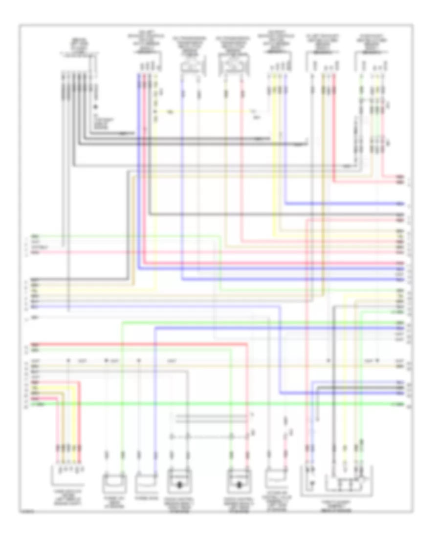
ENGINE PERFORMANCE
2.7L
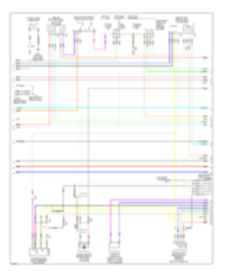
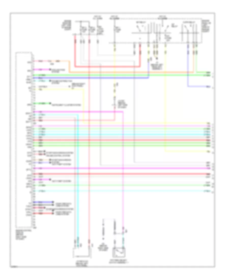
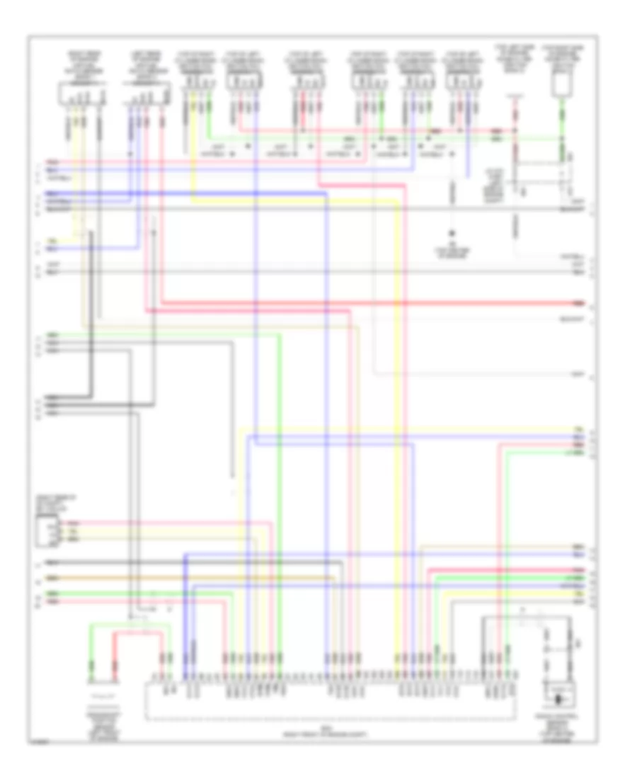
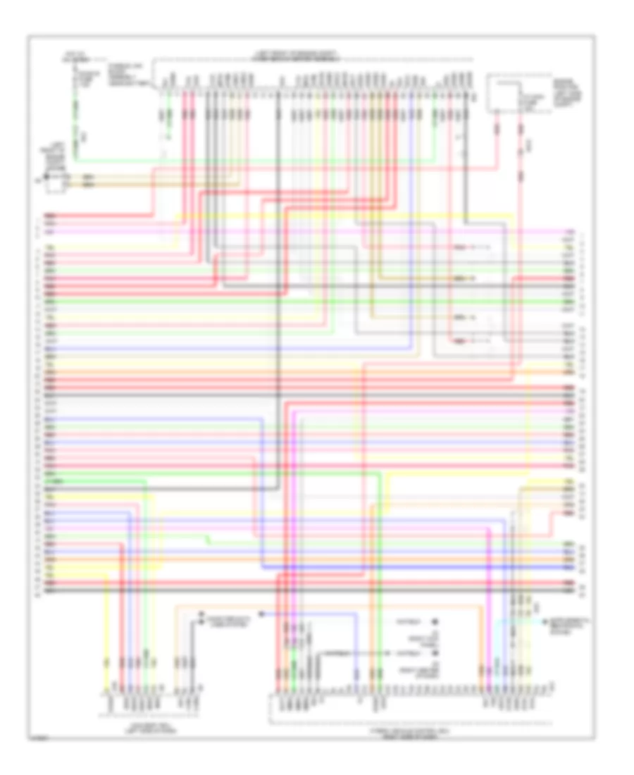
2.7L, Engine Performance Wiring Diagram (1 of 5) for Toyota Highlander SE 2011

List of elements for 2.7L, Engine Performance Wiring Diagram (1 of 5) for Toyota Highlander SE 2011:
- (behind right side of dash) j/c d53 & e24
- (on accelerator pedal bracket) accelerator pedal sensor
- (top front of engine)
- (top of engine)
- A/f fuse 20a
- A7 (behind left headlight assembly)
- Ad11
- Ad13
- Ad9
- Anti-theft system
- B4 (rear of engine)
- B48
- Ba1
- Bb1
- C/opn relay
- Ccs
- Computer data lines system
- Cruise control system
- D53
- D60
- E01
- E03
- E04
- E10
- E11
- E12
- E24
- Ecm (behind right side of dash)
- Efi main relay 2
- Efi relay
- Engine room j/b (left side of engine compt)
- Epa
- Epa2
- Fuel injectors (top of engine)
- Ge01
- Gnd
- Hot at all times
- Hot in on or start
- Igf
- Igf1
- Ignition coil assembly 1
- Ignition coil assembly 2
- Ignition coil assembly 3
- Ignition coil assembly 4
- Igsw
- Igt1
- Igt2
- Igt3
- Igt4
- Imi
- Imo
- Inj 1 fuse 15a
- Inj 2 fuse 10a
- Me01
- Mrel
- Nca
- Pnk
- Red
- Sftu
- Spd
- St1-
- Sta
- Starting/ charging system
- Stp
- Tach
- Transmissions system
- Vcp2
- Vcpa
- Vpa
- Vpa2
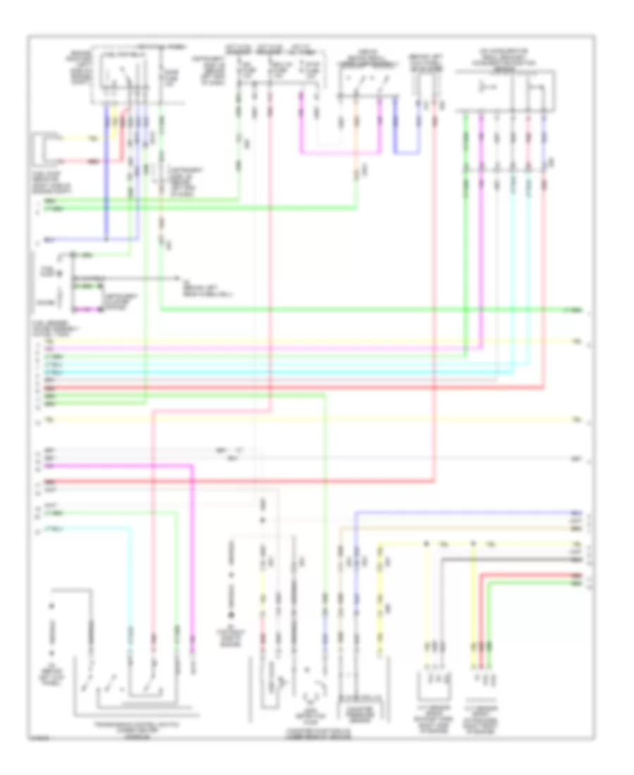
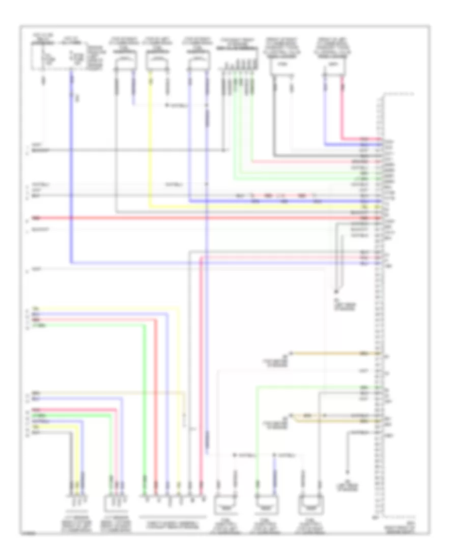
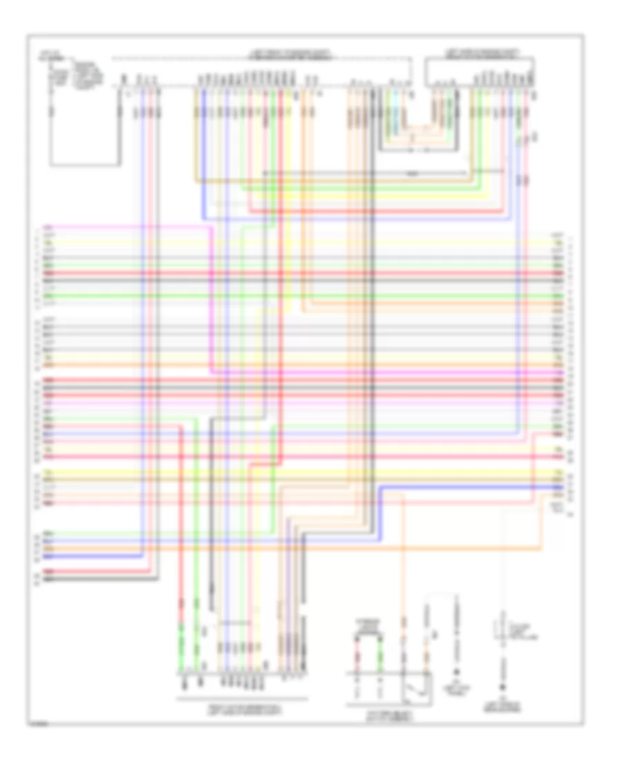
2.7L, Engine Performance Wiring Diagram (2 of 5) for Toyota Highlander SE 2011
List of elements for 2.7L, Engine Performance Wiring Diagram (2 of 5) for Toyota Highlander SE 2011:
- (above brake pedal) stop light switch
- (behind left kick panel) j/c a41, a36 d51 & d62
- (behind left side of dash) j/c a39 & e23
- (behind right side of dash) j/c b47
- (in fuel tank) fuel pump
- (top front of engine) b3
- A1a+
- A1a-
- A39
- A41
- Ad4
- Air fuel ratio sensor (bank 1 sensor 1) (on right exhaust manifold)
- Ba1
- Bd1
- Bd2
- Camshaft timining oil control valve (bank 1 intake) (top of engine)
- D10
- D13
- D3 (behind right side of dash)
- D62
- Do2
- Dp1
- E23
- Ed3
- G12
- Gauge 2 fuse 7.5a
- Ha1a
- Hot at all times
- Hot in on or start
- Ht1b
- Ign fuse 10a
- Instrument panel j/b (behind left end of dash)
- J/c d56 (behind right side of dash)
- Knock control sensor (bank 1) (left side of engine)
- L10
- M13
- Nca
- O2 (behind left rear wheelwell)
- Ox1b
- Oxygen sensor (bank 1 sensor 2) (in exhaust)
- Red
- Stop fuse 10a
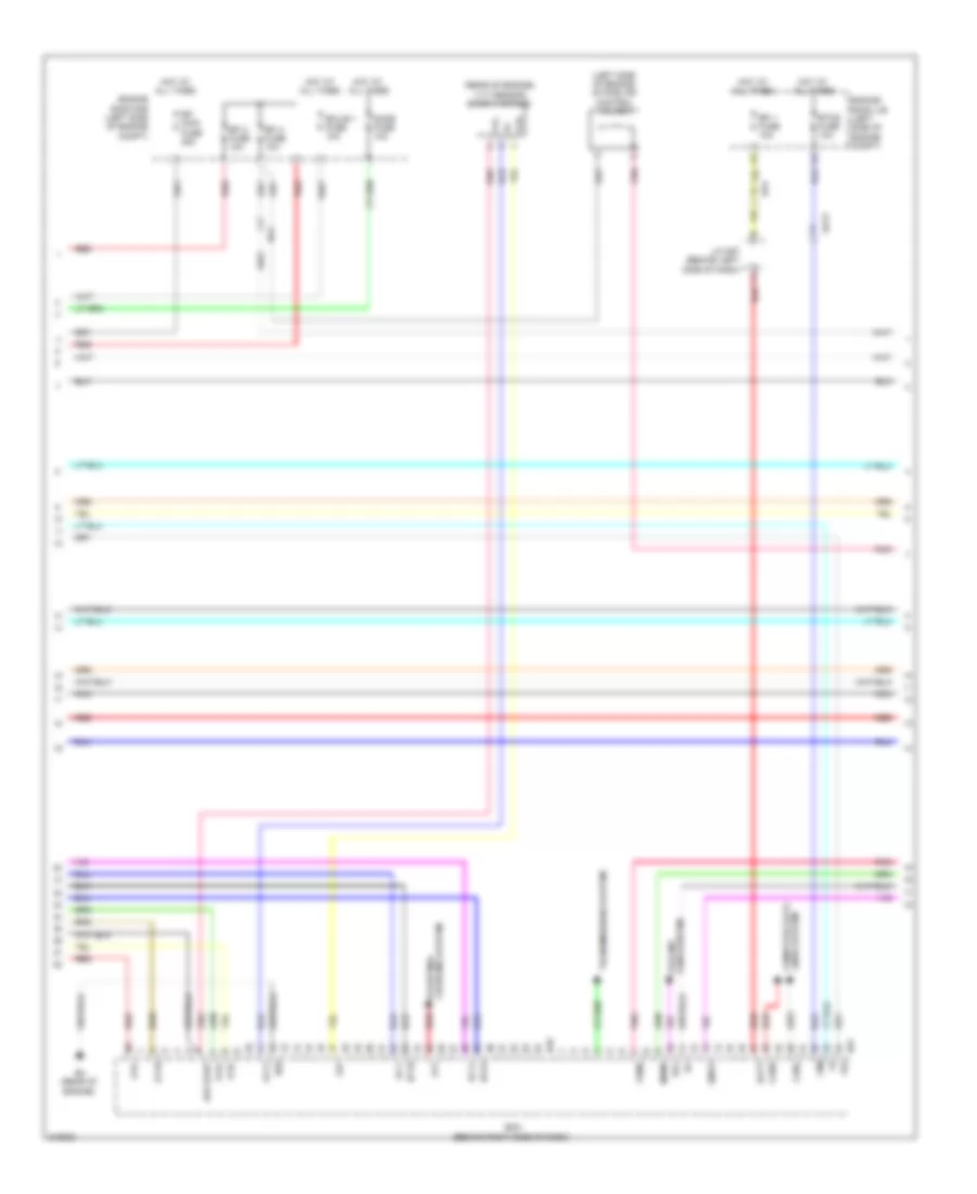
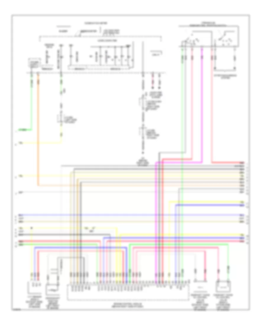
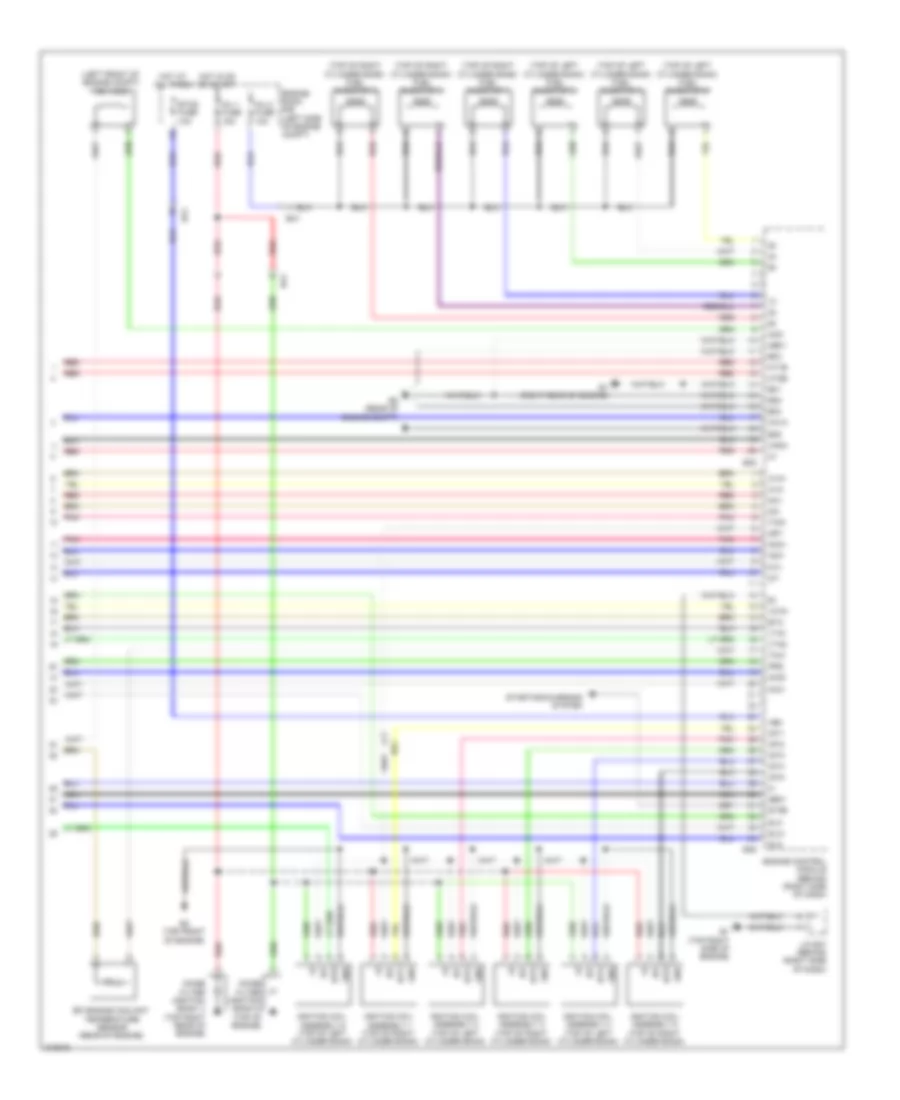
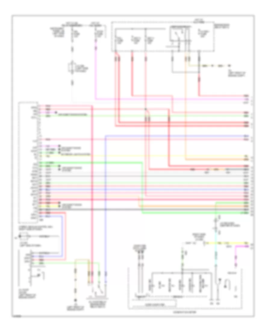
2.7L, Engine Performance Wiring Diagram (3 of 5) for Toyota Highlander SE 2011
List of elements for 2.7L, Engine Performance Wiring Diagram (3 of 5) for Toyota Highlander SE 2011:
- (behind right side of dash)
- (left side of engine) intake air control valve 3
- (rear of engine)
- +b2
- +bm
- A1a+
- A1a-
- Ad13
- Ad4
- Alt
- B4 (rear of engine)
- B49
- Ba1
- Batt
- Canh
- Canl
- Charging system starting/
- Cooling fans system
- D61
- Dome fuse 10a
- E02
- E1 (or g2-)
- Ecm
- Ecu-b 1 fuse 10a
- Efi 1 fuse 10a
- Efi 2 fuse 10a
- Efi 3 fuse 10a
- Efi main fuse 25a
- Engine room j/b (left side of engine compt)
- Engine room r/b (left side of engine compt)
- Etcs fuse 10a
- G2+
- Ha1a
- Hot at all times
- Ht1b
- J/c d57 (behind left side of dash)
- Lines system computer data
- Mpmp
- Nca
- O1b-
- Oc1+
- Oc1-
- Ox1b
- Pnk
- Red
- Rfc
- Snw1
- Transmissions system
- Vcv1
- Vpmp
- Vvi+
- Vvi-
- Vvt sensor (bank 1 intake)
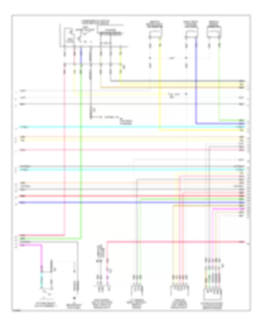
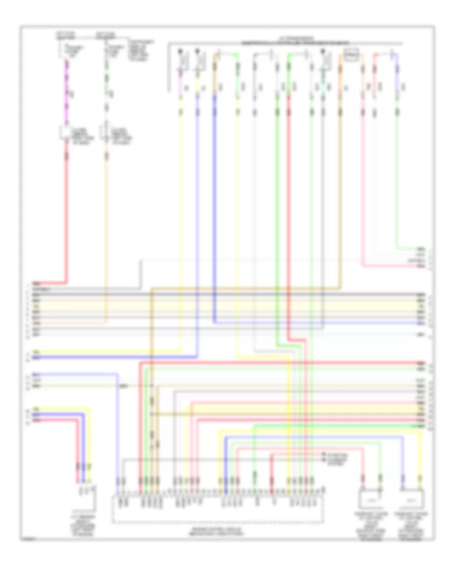
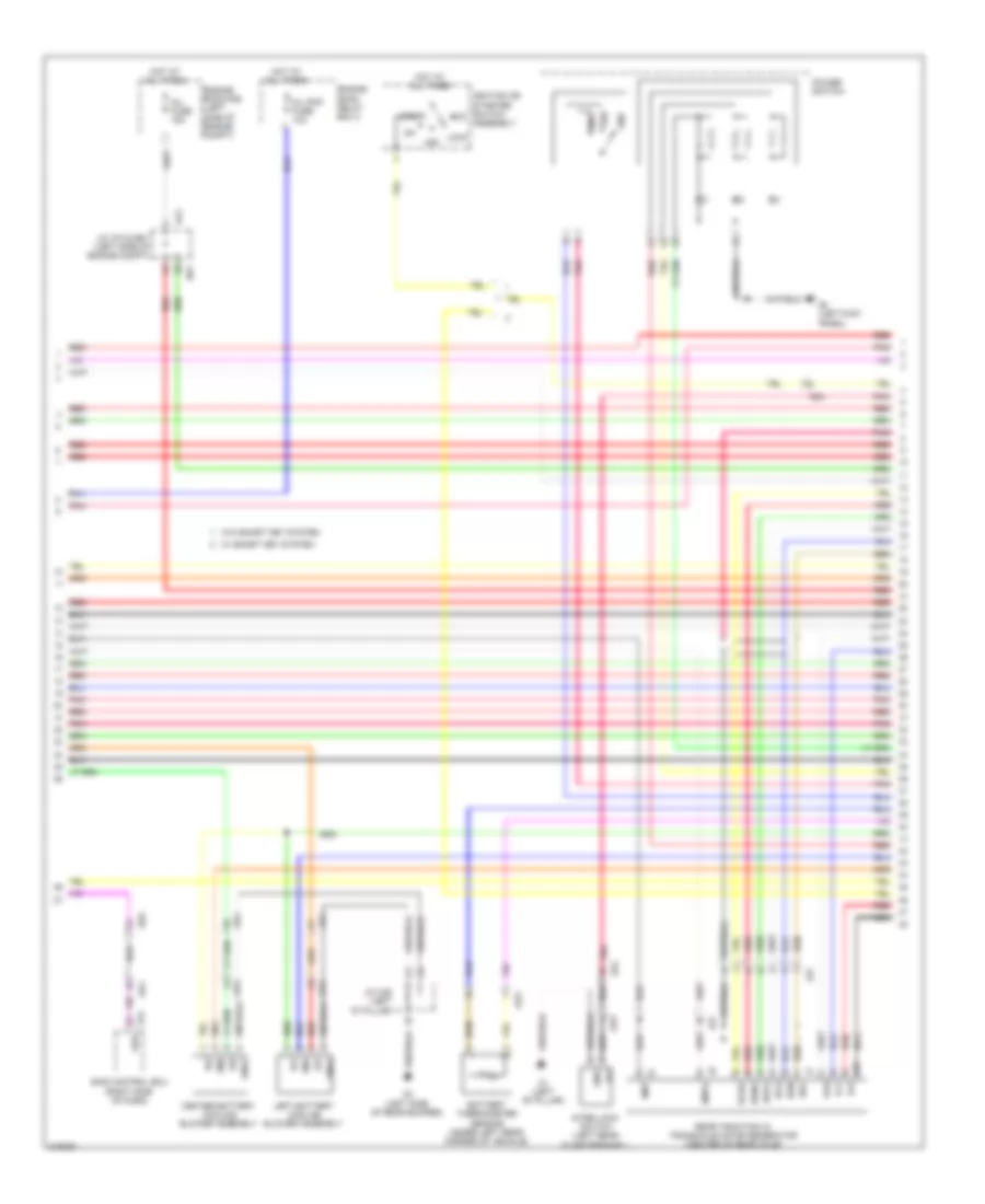
2.7L, Engine Performance Wiring Diagram (4 of 5) for Toyota Highlander SE 2011
List of elements for 2.7L, Engine Performance Wiring Diagram (4 of 5) for Toyota Highlander SE 2011:
- (rear of engine compt) vsv (ejector)
- (rear of engine) purge vsv
- (right front of engine) vsv (acis)
- (under rear of vehicle) canister pump module
- Ad4
- B3 (top front of engine)
- Bd1
- Bd2
- Canh
- Canister pressure sensor
- Canl
- D1 (behind right kick panel)
- Dn2
- Dg1
- E2g
- Gnd
- Intake air control valve actuator (rear of engine)
- Leak detection pump
- Mass air flow meter (left rear of engine compt)
- Nca
- Out
- Pattern select switch assembly 1
- Pnk
- Red
- Skid control ecu w/ actuator (right front of engine compt)
- Sp1
- System data lines computer
- Tha
- Vc2
- Vdd
- Vent valve
- Vve+
- Vve-
- Vvt sensor (bank 1 exhaust) (rear of engine)
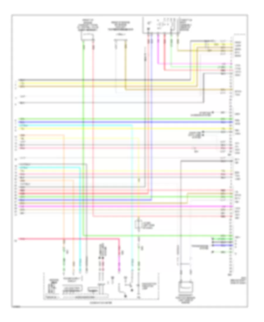
2.7L, Engine Performance Wiring Diagram (5 of 5) for Toyota Highlander SE 2011
List of elements for 2.7L, Engine Performance Wiring Diagram (5 of 5) for Toyota Highlander SE 2011:
- (front of engine) camshaft timing oil control valve (bank 1 exhaust)
- (rear of engine) efi engine coolant temperature sensor
- +b(dome) or ig
- Acis
- Aicv
- B50
- B51
- Ba1
- Bd1
- Bd2
- Buzzer
- Can i/f
- Can+
- Can-
- Combination meter
- Computer data lines system
- Crankshaft position sensor (left side of engine)
- Drive ic
- E2g
- Ecm (behind right side of dash)
- Ed1
- Ed5
- Eia1
- Eknk
- Eppm
- Eta
- Etha
- Ethw
- Ev1+
- Ev1-
- Ia1+
- Ia1-
- Iac1
- Ig2
- Ind lamp master
- J/c d63 (left side of dash)
- Knk1
- Lcd (odo/trip) (a/t position)
- Malfunction indicator lamp
- Micro computer
- Nca
- Ne+
- Ne-
- Nsw
- Oe1+
- Oe1-
- Pbv
- Pnk
- Ppmp
- Prg
- Red
- Starting/ charging system
- System data lines computer
- Tha
- Throttle body assembly (rear of engine)
- Thw
- Transmissions system
- Vce1
- Vcia
- Vcpp
- Vcta
- Vta1
- Vta2
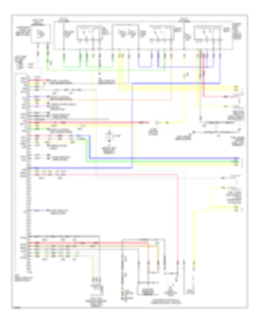
3.5L
3.5L, Engine Performance Wiring Diagram (1 of 6) for Toyota Highlander SE 2011
List of elements for 3.5L, Engine Performance Wiring Diagram (1 of 6) for Toyota Highlander SE 2011:
- (behind right kick panel) d1
- +b2
- A/f fuse 20a
- A/f relay
- A41
- A7 (behind left headlight assembly)
- Accr
- Ad4
- Ad9
- Anti-theft system
- Batt
- C/opn relay
- Canh
- Canl
- Ccs
- Computer data lines system
- Cooling fans system
- Cruise control system
- D12
- D3 (behind right side of dash)
- D60
- D61
- D62
- Dg1
- E10
- E11
- E12
- E13
- Efi 1 fuse 10a
- Efi 2 fuse 10a
- Efi 3 fuse 10a
- Efi main fuse 25a
- Efi relay
- Els2
- Engine control module (behind right side of dash)
- Engine room j/b (left side of engine compt)
- Engine room r/b (left side of engine compt)
- Epa
- Epa2
- Fpc
- Fpr
- Hot at all times
- Igsw
- Imi
- Imo
- Instrument cluster system
- J/c d57 (behind left side of dash)
- J/c d62 & a41 (behind left kick panel)
- Mpmp
- Mrel
- Pattern select switch assembly 1
- Pnk
- Power distribution system
- Red
- Rfc
- Sftd
- Sftu
- Snw1
- Spd
- St1-
- Sta
- Starting/charging system
- Starting/charging system anti-theft system
- Stp
- Stsw
- Tach
- Vcp2
- Vcpa
- Vpa
- Vpa2
- Vpmp
3.5L, Engine Performance Wiring Diagram (2 of 6) for Toyota Highlander SE 2011
List of elements for 3.5L, Engine Performance Wiring Diagram (2 of 6) for Toyota Highlander SE 2011:
- (above brake pedal) stop lamp switch
- (behind left kick panel) j/c a41 & d62
- (on accelerator pedal bracket) accelerator position sensor
- A41
- Ad11
- Ad13
- Ad9
- B1 (top right side of engine)
- Ba1
- Bd1
- Bd3
- Canister pressure sensor
- Canister pump module (under rear of vehicle)
- D13
- D4 (behind left kick panel)
- D62
- Dn2
- Do2
- Dome fuse 10a
- Ecu ig1 fuse 10a
- Ed1
- Engine room r/b (left side of engine compt)
- Ex+
- Ex-
- F11
- Fuel m
- Fuel pmp relay
- Fuel pump resistor (right side of engine compt)
- Fuel sender gauge assembly (in fuel tank)
- Gauge
- Hot at all times
- Hot in on or start
- Ign fuse 10a
- Instrument cluster system
- Instrument side j/b (behind left end of dash)
- L10
- Leak detection pump
- M13
- O2 (behind left rear wheelwell)
- Pnk
- Pump
- Red
- Sftd
- Sftu
- Stop fuse 10a
- Transmission control switch (under center console)
- Vc2
- Vent valve
- Vvr+
- Vvr-
- Vvt sensor (bank1 exhaust side) (right side of engine)
- Vvt sensor (bank1 intake side) (right front of engine)
3.5L, Engine Performance Wiring Diagram (3 of 6) for Toyota Highlander SE 2011
List of elements for 3.5L, Engine Performance Wiring Diagram (3 of 6) for Toyota Highlander SE 2011:
- (transaxle) park/neutral position switch
- +b(dome) or ig
- B51
- Bb1
- Buzzer
- Camshaft timing oil control valve (bank 2 exhaust side) (left front of engine)
- Camshaft timing oil control valve (bank 2 intake side) (left front of engine)
- Can i/f
- Charge ind
- Combination meter
- Computer data lines system
- Crankshaft position sensor (left front of engine)
- D3 (behind right side of dash)
- D53
- Drive ic
- Dsl
- E24
- Econ ind
- Ed5
- Engine control module (behind right side of dash)
- Ev1+
- Ev1-
- Ev2+
- Ev2-
- Ex+
- Ex-
- Ex1b
- Ex2b
- Ig2+
- J/c d53 & e24 (behind right side of dash)
- J/c d56 (behind right side of dash)
- J/c d63 (left side of dash)
- Lcd (odo/trip) (a/t position)
- Malfunction ind
- Master ind
- Micro computer
- N r
- Ne+
- Ne-
- Oc2+
- Oc2-
- Oe2+
- Oe2-
- Ox1b
- Ox2b
- Pnk
- Red
- Snow ind
- Speedometer
- Starting/charging system
- Vc2
- Vcv1
- Vcv2
- Vv1+
- Vv1-
- Vv2+
- Vv2-
- Vvt sensor (bank 2 exhaust side) (left side of engine)
3.5L, Engine Performance Wiring Diagram (4 of 6) for Toyota Highlander SE 2011
List of elements for 3.5L, Engine Performance Wiring Diagram (4 of 6) for Toyota Highlander SE 2011:
- (in transmission) electronically controlled transmission solenoid
- Alt
- B50
- Bb1
- Bd1
- Camshaft timing oil control valve (bank 1 exhaust side) (right front of engine)
- Camshaft timing oil control valve (bank 1 intake side) (right front of engine)
- Dsl
- E2g
- Ed3
- Ekn2
- Eknk
- Engine control module (behind right side of dash)
- Etha
- Ethw
- G12
- Gauge 1 fuse 10a
- Gauge 2 fuse 7.5a
- H16
- Hot in on or start
- Igt6
- Instrument side j/b (behind left end of dash)
- J/c b46 (behind right side of dash)
- J/c e23 (behind left side of dash)
- Knk1
- Knk2
- Nsw
- Oc1+
- Oc1-
- Oe1+
- Oe1-
- Pnk
- Ppmp
- Red
- Sl1+
- Sl1-
- Sl2+
- Sl2-
- Sl3+
- Sl3-
- Slt+
- Slt-
- Starting/ charging system
- Tha
- Tho
- Vvl+
- Vvl-
- Vvt sensor (bank 2 intake side) (left front of engine)
3.5L, Engine Performance Wiring Diagram (5 of 6) for Toyota Highlander SE 2011
List of elements for 3.5L, Engine Performance Wiring Diagram (5 of 6) for Toyota Highlander SE 2011:
- (behind left side of dash) j/c b47
- (in exhaust) heated oxygen sensor (bank 1 sensor 2)
- (in left exhaust) heated oxygen sensor (bank 2 sensor 2)
- (on left exhaust manifold) air fuel ratio sensor (bank 2 sensor 1)
- (on right exhaust manifold) air fuel ratio sensor (bank 1 sensor 1)
- (on transmission) transmission revolution sensor (counter gear)
- (on transmission) transmission revolution sensor (turbine)
- A1a+
- A1a-
- A2a+
- A2a-
- B1 (top right side of engine)
- Ba1
- Bd1
- Bd1
- Dp1
- E2g
- Ha1a
- Ha2a
- Ht1b
- Ht2b
- Intake air control valve assembly 3 (left side of engine)
- Knock control sensor (bank 1) (right rear of engine)
- Knock control sensor (bank 2) (left rear of engine)
- Mass air flow meter (left rear of engine compt)
- Nca
- Ox1b
- Ox2b
- Pnk
- Purge (acis)
- Purge vsv (rear of engine)
- Red
- Tha
- Throttle body assembly (rear of engine)
- Vta
- Vta2
3.5L, Engine Performance Wiring Diagram (6 of 6) for Toyota Highlander SE 2011
List of elements for 3.5L, Engine Performance Wiring Diagram (6 of 6) for Toyota Highlander SE 2011:
- (left front of engine compt) vsv (acm)
- (top of left cylinder bank) fuel injector 2
- (top of left cylinder bank) fuel injector 4
- (top of left cylinder bank) fuel injector 6
- (top of right cylinder bank) fuel injector 1
- (top of right cylinder bank) fuel injector 3
- (top of right cylinder bank) fuel injector 5
- +bm
- A1a+
- A1a-
- A2a+
- A2a-
- Acis
- Acm
- Aicv
- B1 (right rear of engine)
- B1 (top right side of engine)
- B2 (rear of engine compt)
- B3 (top front of engine)
- B48
- B49
- Ba1
- Bb1
- E01
- E02
- E03
- E04
- E05
- Efi engine coolant temperature sensor (rear of engine)
- Engine control module (behind (right side of dash)
- Engine room r/b (left side of engine compt)
- Eta
- Etcs fuse 10a
- Ge01
- Gnd
- Ha1a
- Ha2a
- Hot at all times
- Hot in on or start
- Ht1b
- Ht2b
- Igf
- Igf1
- Ignition coil assembly 1 (top of right cylinder bank)
- Ignition coil assembly 2 (top of left cylinder bank)
- Ignition coil assembly 3 (top of right cylinder bank)
- Ignition coil assembly 4 (top of left cylinder bank)
- Ignition coil assembly 5 (top of right cylinder bank)
- Ignition coil assembly 6 (top of left cylinder bank)
- Igt1
- Igt2
- Igt3
- Igt4
- Igt5
- Igt6
- Inj 1 fuse 15a
- Inj 2 fuse 10a
- J/c b47 (behind (right side of dash)
- Me01
- Nc+
- Nc-
- Nca
- Noise filter (ignition bank 1) (top right rear of engine)
- Noise filter (ignition bank 2) (top of engine)
- Nt+
- Nt-
- Pnk
- Prg
- Red
- Sl2-
- Sl3+
- Sl3-
- Star
- Starting/charging system
- Tho1
- Thw
- Vcta
- Vta1
- Vta2
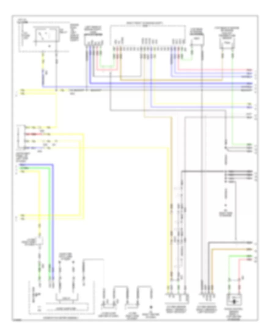
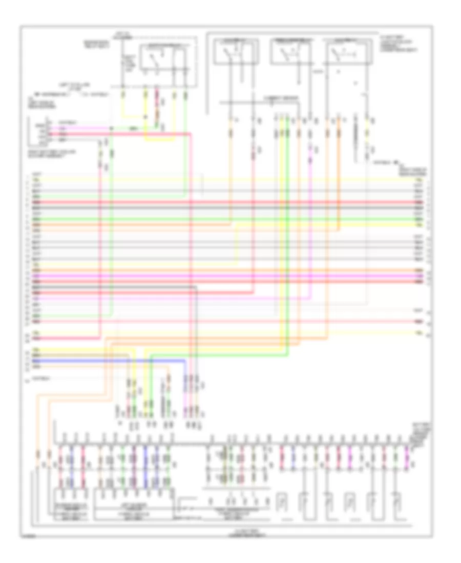
3.5L HYBRID
3.5L Hybrid, Engine Controls Wiring Diagram (1 of 4) for Toyota Highlander SE 2011
List of elements for 3.5L Hybrid, Engine Controls Wiring Diagram (1 of 4) for Toyota Highlander SE 2011:
- (left side of dash) j/c a58
- (top center of engine) b5
- +b2
- A3 (left front of engine compt)
- A67
- A7 (behind left headlight assembly)
- Ad10
- Ad12
- Ad13
- Ad4
- Ad9
- Ao2
- Ba3
- Batt
- C/opn relay
- Can+
- Can-
- Canh
- Canister pressure sensor
- Canister pump module (under center of vehicle)
- Canl
- Ccv2
- Computer data lines system
- Do2
- Ecm (right front of engine compt)
- Ed3
- Efi 1 fuse 10a
- Efi 2 fuse 10a
- Efi 3 fuse 10a
- Efi main fuse 30a
- Efi main relay
- Engine room r/b (left side of engine compt)
- Eppm
- F/pmp fuse 15a
- F/pmp relay
- Fpr
- Fuel
- Fuel gauge sender (fuel tank assembly)
- Fuel pump resistor (right side of engine compt)
- Fuel tank pressure sensor (fuel tank assembly)
- Fuel vapor containment valve (under rear
- Fuo
- Go1
- Go2
- Hot at all times
- Hot w/ ig2 relay energized
- Hybrid system circuit
- Hybrid system circuit cooling fans system
- Ign fuse 10a
- Igsw
- Instrument panel j/b (behind left end of dash)
- J/c a57
- J/c d57 (center of dash)
- Leak detection pump
- Lido
- Lst1
- Lst2
- M13
- Mpmp
- Mrel
- O2 (left side of rear bumper)
- Od2
- Of vehicle)
- Ok1
- Pnk
- Ppmp
- Ptnk
- Red
- Rfc
- Trunk, tailgate, fuel doors system
- Vcpp
- Vent valve
- Ko1
3.5L Hybrid, Engine Controls Wiring Diagram (2 of 4) for Toyota Highlander SE 2011
List of elements for 3.5L Hybrid, Engine Controls Wiring Diagram (2 of 4) for Toyota Highlander SE 2011:
- (left rear of engine compt) mass air flow meter
- (right front of engine compt) ecm
- (top rear of engine) efi engine coolant temperature sensor
- (top rear of engine) vsv (purge)
- A/f fuse 20a
- A/f relay
- A1a-
- A2a-
- Ad13
- Ad9
- B4 (right side of engine)
- B57
- Ba2
- Ba3
- Bd1
- Can i/f
- Canh
- Canl
- Chk
- Combination meter assembly
- Computer data lines system
- D3 (right center of dash)
- D53
- Dp2
- E24
- E2g
- Ed5
- Engine room j/b (left side of engine compt)
- Etha
- Ethw
- Ex1b
- Fuci
- Fuwi
- Hot at all times
- Ht1b
- Ht2b
- Ig2
- Igt1
- Igt3
- Igt6
- Ind malfunction
- Instrument panel j/b (left side of dash)
- J/c d56 (right side of dash)
- J/c e24 & d53 (center of dash)
- Knock control sensor (bank 1) (top center of engine)
- M11
- Micro computer
- Nca
- Od2
- Ox1b
- Ox2b
- Oxygen sensor (bank 1 sensor 2) (right exhaust)
- Oxygen sensor (bank 2 sensor 2) (left exhaust)
- Ok1
- Pnk
- Prg
- Red
- Tha
3.5L Hybrid, Engine Controls Wiring Diagram (3 of 4) for Toyota Highlander SE 2011
List of elements for 3.5L Hybrid, Engine Controls Wiring Diagram (3 of 4) for Toyota Highlander SE 2011:
- (left rear of engine) air fuel ratio sensor (bank 2 sensor 1)
- (right rear of engine) air fuel ratio sensor (bank 1 sensor 1)
- (right rear of of compt) efi vacuum sensor
- (top left side of engine) noise filter (ignition bank 2)
- (top of left cylinder bank) ignition coil assembly 2
- (top of left cylinder bank) ignition coil assembly 4
- (top of left cylinder bank) ignition coil assembly 6
- (top of right cylinder bank) ignition coil assembly 1
- (top of right cylinder bank) ignition coil assembly 3
- (top of right cylinder bank) ignition coil assembly 5
- (top right side of engine) noise filter (ignition bank 1)
- A1a+
- A1a-
- A2a+
- A2a-
- A73
- B5 (top center of engine)
- B57
- B81
- Bd1
- Crankshaft position sensor (left front of engine)
- Ecm (right front of engine compt)
- Eknk
- Enk2
- Epim
- Eta
- Ex2b
- Ge01
- Gnd
- Ha1a
- Ha2a
- Igf
- Igt1
- Igt2
- Igt3
- Igt4
- Igt5
- Igt6
- J/c a73 & b81 (left side of engine compt)
- Knk1
- Knk2
- Knock control sensor (bank 2) (top center of engine)
- Nca
- Ne+
- Ne-
- Ox2b
- Pim
- Pim vc e2
- Pnk
- Red
- Tha
- Thw
- Vcta
- Vcv1
- Vcv2
- Vpim
- Vta1
- Vta2
- Vv1+
- Vv1-
- Vv2+
- Vv2-
3.5L Hybrid, Engine Controls Wiring Diagram (4 of 4) for Toyota Highlander SE 2011
List of elements for 3.5L Hybrid, Engine Controls Wiring Diagram (4 of 4) for Toyota Highlander SE 2011:
- (front of left cylinder bank) camshaft timing oil control valve (bank 2 intake)
- (front of right cylinder bank) camshaft timing oil control valve (bank 1 intake)
- (top of left cylinder bank) fuel injector 2
- (top of right cylinder bank) fuel injector 1
- (top of right cylinder bank) fuel injector 5
- (top right front of engine) egr valve assembly
- +b1
- +bm
- Ad9
- B3 (left rear of engine)
- B5 (top center of engine)
- B57
- Ba2
- Ba3
- Dp2
- E01
- E02
- E03
- E04
- E05
- Ecm (right front of engine compt)
- Egr1
- Egr2
- Egr3
- Egr4
- Engine room r/b (left side of engine compt)
- Etcs fuse 15a
- Fuel injector 3 (top of right cylinder bank)
- Fuel injector 4 (top of left cylinder bank)
- Fuel injector 6 (top of left cylinder bank)
- Ha1a
- Ha2a
- Hot at all times
- Hot w/ ig2 relay energized
- Ht1b
- Ht2b
- Igf1
- Inj fuse 15a
- Me01
- Oc1+
- Oc1-
- Oc2+
- Oc2-
- Pnk
- Red
- Throttle body assembly (top right rear of engine)
- Vta
- Vta2
- Vvl+
- Vvl-
- Vvr+
- Vvr-
- Vvt sensor (bank 1 intake) (front of right cylinder bank)
- Vvt sensor (bank 2 intake) (front of left cylinder bank)
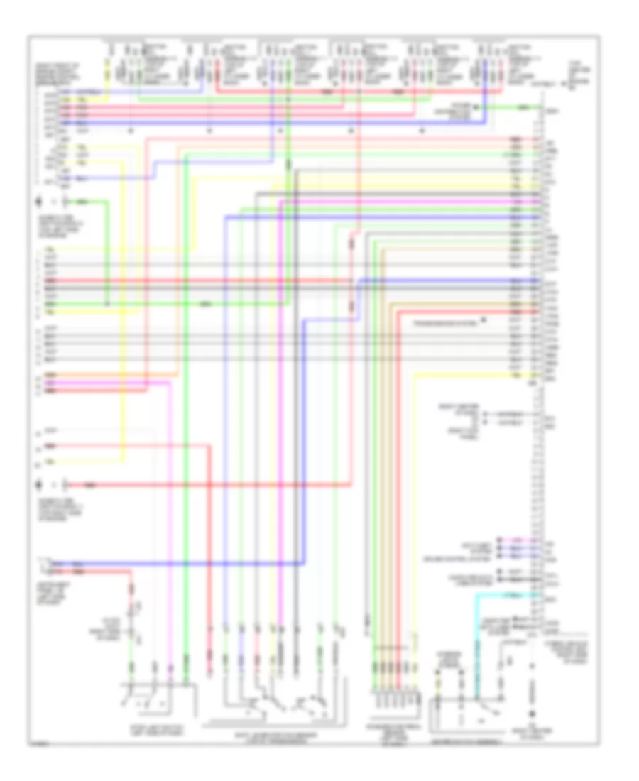
3.5L Hybrid, Hybrid System Wiring Diagram (1 of 6) for Toyota Highlander SE 2011
List of elements for 3.5L Hybrid, Hybrid System Wiring Diagram (1 of 6) for Toyota Highlander SE 2011:
- (right side of dash) j/c d56
- +b2
- A3 (left front of engine compt)
- A65
- Ad10
- Ad4
- Air conditioning system
- Can i/f
- Charge ind
- Clk
- Combination meter
- Computer data lines system
- D53
- Drive ic
- E24
- Econ ind
- Ed5
- Engine room relay box 2
- Et1
- Ev ind
- Exterior lights system
- Fctl
- Gmt
- Gmtg
- Hot at all times
- Hot w/ ig2 relay energized
- Hv r/b 1 fuse 30a
- Hybrid vehicle control ecu (right side of dash)
- Ig2
- Igct 2 fuse 10a
- Igct 3 fuse 10a
- Igct main relay
- Ign fuse 10a
- Ilk
- Ind lamp multifunction
- Instrument panel j/b (left side of dash)
- Ite
- Iwp
- J/c a40 (left end of dash)
- J/c a58 (left side of dash)
- J/c d53 & e24 (center of dash)
- Master ind
- Micro computer
- Mmt
- Mmtg
- Niwp
- Nodd
- Od1
- Oil pump motor (left front of engine compt)
- Oil pump relay (engine room relay box 3)
- Opg
- Opm1
- Opm2
- Opst
- Pcu fuse 10a
- Pnk
- Ready ind
- Red
- Rmt
- Rmtg
- Si1
- Si2
- Sio
- Stb
- Stop fuse 10a
- Vlo
3.5L Hybrid, Hybrid System Wiring Diagram (2 of 6) for Toyota Highlander SE 2011
List of elements for 3.5L Hybrid, Hybrid System Wiring Diagram (2 of 6) for Toyota Highlander SE 2011:
- A44
- A73
- Acc
- Ad4
- B81
- Battery thermometer sensor (under left rear corner of vehicle)
- Center battery cooling blower assembly
- D4 (left kick panel)
- Ed5
- Engine room r/b (left side of engine compt)
- Engine room relay box 3
- Gnd
- Gnd1
- Gnd2
- Hot at all times
- Ig1
- Ig2
- Ignition or starter switch assembly
- Ilk
- Inj fuse 15a
- Inter lock switch (left rear quarterpanel)
- J/c a73 & b81 (left side of engine compt)
- J/c o38 (left "d" pillar)
- Left battery cooling blower assembly
- Lock
- Nca
- O1 (left "b" pillar)
- O2 (left side of rear bumper)
- Od3
- Off
- Oil pmp fuse 10a
- Pnk
- Power switch
- R-u
- R-v
- R-w
- Rcs
- Rcsg
- Rear traction w/ transaxle motor generator (center of rear axle)
- Red
- Rmt
- Rmtg
- Rrf
- Rrfg
- Rsn
- Rsng
- Si1
- Si2
- Skid control ecu (right side of dash)
- Spd
- Ss1
- Ss2
- Start
- Vm1
- Vm2
- W/ smart key system
- W/o smart key system
- J10
- Ja2
3.5L Hybrid, Hybrid System Wiring Diagram (3 of 6) for Toyota Highlander SE 2011
List of elements for 3.5L Hybrid, Hybrid System Wiring Diagram (3 of 6) for Toyota Highlander SE 2011:
- (left front of engine compt) inverter/converter assembly
- (left front of engine compt) j/c a75
- A64
- Abfs
- Ad12
- Ao2
- B2+
- Batt
- Bth+
- Bth-
- Canh
- Canl
- Clk+
- Clk-
- Computer data lines system
- D1 (right kick panel)
- D10
- D3 (right center of dash)
- D72
- Dc/dc-s fuse 7.5a
- Drn1
- Drn2
- Drn3
- Drn4
- Drn5
- Drn7
- Drn8
- E01
- Engine room r/b (left side of engine compt)
- Ethb
- Evsw
- Fusible link block assembly (near battery)
- Gnd1
- Gnd2
- Hot at all times
- Hsdn
- Htm+
- Htm-
- Hv main fuse 10a
- Hybrid vehicle control ecu (right side of dash)
- Ig1
- Igct
- Ilki
- Ilko
- Inds
- Indw
- Main body ecu (left side of dash)
- Mth+
- Mth-
- Nca
- Nodd
- Od3
- Pnk
- Rcs
- Rcsg
- Rdy
- Red
- Req+
- Req-
- Rrf
- Rrfg
- Rsn
- Rsng
- Smrb
- Smrg
- Smrp
- Spdi
- Ssw1
- Ssw2
- Stsw
- Swil
- Thb
- Vlo
3.5L Hybrid, Hybrid System Wiring Diagram (4 of 6) for Toyota Highlander SE 2011
List of elements for 3.5L Hybrid, Hybrid System Wiring Diagram (4 of 6) for Toyota Highlander SE 2011:
- (left front of engine compt) inverter/converter assembly
- (left side of engine compt) front motor generator 1
- Amd
- B58
- B59
- B60
- B61
- Ba2
- Cbi
- Cei
- D4 (left kick panel)
- Dc/dc fuse 150a
- Drn6
- Dg1
- Engine room j/b (left side of engine compt)
- Front motor generator 2 (left side of engine compt)
- Gcs
- Gcsg
- Gmt
- Gmtg
- Grf
- Grfg
- Gsn
- Gsng
- Hot at all times
- Interior lights system
- J/c o38 (left "d" pillar)
- Mcs
- Mcsg
- Mmt
- Mmtg
- Mrf
- Mrfg
- Mscg
- Msn
- Msng
- Nca
- O2 (left side of rear bumper)
- Pattern select switch assembly
- Pnk
- R-u
- R-v
- R-w
- Red
- Z25
- Z26
- Z27
- Z28
3.5L Hybrid, Hybrid System Wiring Diagram (5 of 6) for Toyota Highlander SE 2011
List of elements for 3.5L Hybrid, Hybrid System Wiring Diagram (5 of 6) for Toyota Highlander SE 2011:
- (left "d" pillar) j/c o38
- Ad4
- Batt fan fuse 30a
- Batt fan relay
- Battery voltage sensor (under rear seat) z18
- Bth+
- Bth-
- Busbar module center
- Current sensor
- Engine room relay box 3
- Gb0
- Gb1
- Gb2
- Gb3
- Gb4
- Gb5
- Gg0
- Gib
- Gnd
- Gnd0
- Hot at all times
- Hv battery (under rear seat)
- Hv battery junction block assembly (under rear seat)
- Hybrid vehicle battery
- Ig0
- Igct
- Left busbar module
- Main relay
- O2 (left side of rear bumper)
- O3 (right side of rear bumper)
- Od3
- Oz3
- Oz3 red
- Pnk
- Pnk vb13
- Precharge relay
- Red
- Red vb15
- Right battery cooling blower assembly
- Right busbar module
- Service plug
- Si0
- Tb0
- Tb1
- Tb2
- Tb3
- Tb4
- Tb5
- Vb1
- Vb10
- Vb14
- Vb2
- Vb3
- Vb4
- Vb5
- Vb6
- Vb8
- Vb9
- Vc1
- Vc10
- Vc11
- Vc12
- Vc13
- Vc14
- Vc15
- Vc2
- Vc3
- Vc4
- Vc5
- Vc6
- Vc7
- Vc8
- Vc9
- Vib
- Vm0
- Vm1
- Vm2
- Vmo
- Z20
- Z18
- Z19
- Z20
- Z21
- Z29
- Z30
- Z31
- Z32
- Z35
- Z36
- Z37
- Z38
- Z39
3.5L Hybrid, Hybrid System Wiring Diagram (6 of 6) for Toyota Highlander SE 2011
List of elements for 3.5L Hybrid, Hybrid System Wiring Diagram (6 of 6) for Toyota Highlander SE 2011:
- (right center of dash) d3
- (right front of engine compt) engine control module (ecm)
- (top center of engine) b5
- +b1
- A66
- A67
- A74
- Accelerator pedal sensor (left side of dash)
- Anti-theft system
- B57
- Ba3
- C13
- Ca1h
- Ca1l
- Ca3n
- Ca3p
- Ccs
- Clk+
- Clk-
- Computer data lines system
- Cruise control system
- D1 (right kick panel)
- D3 (right center of dash)
- D73
- D77
- Drn2
- Dg1
- E02
- E12
- Eco
- Ep1
- Ep2
- F15
- Gnd
- Go1
- Go2
- Heater switch assembly
- Hsdn
- Htm+
- Htm-
- Hybrid vehicle control ecu (right side of dash)
- Igf
- Igf1
- Ignition coil 1 assembly 1 (top of right cylinder bank)
- Ignition coil assembly 2 (top of left cylinder bank)
- Ignition coil assembly 3 (top of right cylinder bank)
- Ignition coil assembly 4 (top of left cylinder bank)
- Ignition coil assembly 5 (top of right cylinder bank)
- Ignition coil assembly 6 (top of left cylinder bank)
- Igsw
- Igt1
- Igt2
- Igt3
- Igt4
- Igt5
- Igt6
- Imi
- Imo
- Instrument panel j/b (left side of dash)
- Interior lights system
- J/c a74 & d77 (right side of dash)
- Mrel
- Mth+
- Mth-
- Nca
- Noise filter (ignition bank 1) (top right side of engine)
- Noise filter (ignition bank 2) (top left side of engine)
- Pnk
- Power distribution system
- Ppos
- Red
- Req+
- Req-
- Shift lever position sensor (top of transmission)
- St1-
- St2
- Stop light switch (left side of dash)
- Stp
- Transmissions system
- Vcp1
- Vcp2
- Vpa1
- Vpa2