ENGINE PERFORMANCE
2.4L
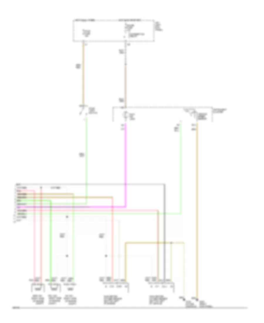
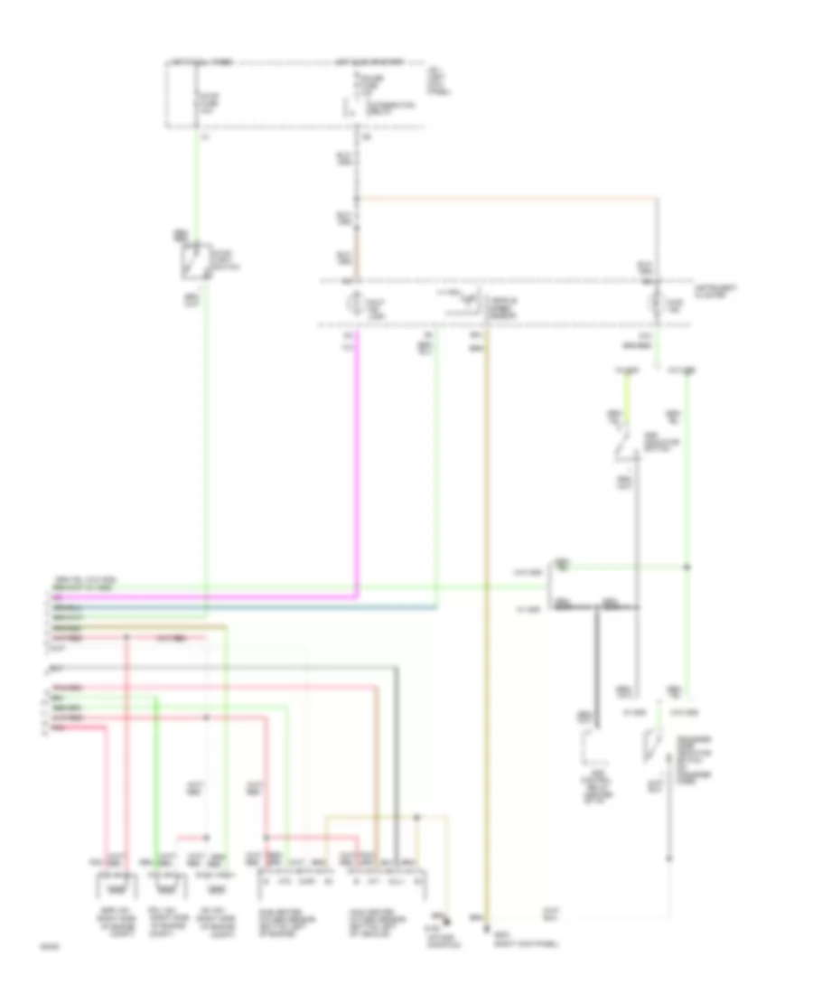
2.4L, Engine Performance Wiring Diagrams, 2-Wheel Drive (1 of 2) for Toyota Pickup SR5 1994

List of elements for 2.4L, Engine Performance Wiring Diagrams, 2-Wheel Drive (1 of 2) for Toyota Pickup SR5 1994:
- #10
- #20
- (closed in park & neutral)
- (left
- (left kick panel)
- (right
- (right side of engine compt)
- (right side of engine)
- (tachometer)
- *80a-m/t
- +b1
- A/t
- A3 j/b 1 kick panel)
- Acc
- Alt fuse 100a
- Batt
- Circuit opening relay (behind right side of i/p)
- Cluster system
- Coil wire
- Data link connector 1
- Distributor
- E21
- Efi fuse 15a
- Efi main relay
- Egr
- Egr gas temperature sensor (right rear of engine)
- Engine control module (right kick panel)
- Engine coolant temperature sensor (right front of engine)
- Eo1
- Eo2
- Fpu
- Fuel injectors
- Fuel pump (in fuel tank)
- G100 (left fender)
- G120 (intake
- G200
- Hot at all times
- Hot in on or start
- Ht1
- Ht2
- Idl
- Ig2
- Igf
- Ign fuse 7.5a
- Igniter
- Ignition coil and igniter (left side of engine compt)
- Ignition switch
- Igt
- Instrument
- J/b 1 (left kick panel)
- Lock
- M/t
- Manifold)
- Noise filter (left side engine compt)
- Nsw
- Ox1
- Ox2
- Park/ neutral position switch (on transmission)
- Pnk
- R/b 2 engine compt)
- Red
- Spd
- St1
- Sta
- Start
- Starter relay
- Starting
- Starting system
- Stj
- Stp
- System
- Te2
- Tha
- Thg
- Throttle position sensor
- Thw
- Vcc
- Volume air flow meter (left front engine compt)
- Vta
2.4L, Engine Performance Wiring Diagrams, 2-Wheel Drive (2 of 2) for Toyota Pickup SR5 1994
List of elements for 2.4L, Engine Performance Wiring Diagrams, 2-Wheel Drive (2 of 2) for Toyota Pickup SR5 1994:
- (right side
- As vsv
- B12
- Compt)
- Egr vsv
- Fpu vsv
- G120 (intake manifold)
- G203 (right kick panel)
- Gauge fuse 10a
- Hot at all times
- Hot in on or start
- Ht1
- Ht2
- Instrument cluster
- Integration relay
- J/b 1 (left kick panel)
- Main heated oxygen sensor (bottom left of vehicle)
- Malf. ind. lamp
- Of engine
- Of engine compt)
- Oxl1
- Oxr1
- Pnk
- Red
- Stop fuse 15a
- Stop light switch
- Sub heated oxygen sensor (bottom left of engine)
- Vehicle speed sensor
2.4L, Engine Performance Wiring Diagrams, A/T with 4-Wheel Drive (1 of 2) for Toyota Pickup SR5 1994
List of elements for 2.4L, Engine Performance Wiring Diagrams, A/T with 4-Wheel Drive (1 of 2) for Toyota Pickup SR5 1994:
- #10
- #20
- (intake
- (left
- (left kick panel)
- (right
- (right side of engine compt)
- (right side of engine)
- (tachometer)
- +b1
- 4wd
- A3 j/b 1 kick panel)
- Acc
- Alt fuse 100a
- Batt
- Circuit opening relay (behind right side of i/p)
- Cluster system
- Coil wire
- Cruise control system
- Data link connector 1
- Distributor
- E21
- Efi fuse 15a
- Efi main relay
- Egr
- Egr gas temperature sensor (right rear of engine)
- Engine control module (right kick panel)
- Engine coolant temperature sensor (right front of engine)
- Eo1
- Eo2
- Fpu
- Fuel injectors
- Fuel pump (in fuel tank)
- G100 (left fender)
- G120
- G200
- Hot at all times
- Hot in on or start
- Ht1
- Ht2
- Idl
- Ig2
- Igf
- Ign fuse 7.5a
- Igniter
- Ignition coil and igniter (left side of engine compt)
- Ignition switch
- Igt
- Instrument
- J/b 1 (left kick panel)
- Knk
- Knock sensor (right side of engine)
- Lock
- Manifold)
- Noise filter (left side engine compt)
- Od1
- Od2
- Ox1
- Ox2
- Park/neutral position switch (on transmission) (closed in park and neutral)
- Pnk
- Pwr
- R/b 2 engine compt)
- Red
- Sp1
- Sp2
- St1
- Sta
- Start
- Starter relay
- Starting
- Starting system
- Stj
- Stp
- System
- Te2
- Tha
- Thg
- Throttle position sensor
- Thw
- Vcc
- Volume air flow meter (left front engine compt)
- Vta
2.4L, Engine Performance Wiring Diagrams, A/T with 4-Wheel Drive (2 of 2) for Toyota Pickup SR5 1994
List of elements for 2.4L, Engine Performance Wiring Diagrams, A/T with 4-Wheel Drive (2 of 2) for Toyota Pickup SR5 1994:
- (center of i/p)
- (intake manifold)
- (on trans- mission)
- (right
- (right kick panel)
- (right side
- 4wd
- 4wd ind.
- Add
- Add indicator switch
- As vsv
- B10
- B12
- Cig fuse 15a
- Column shift
- Compt)
- Control
- Cruise control system
- D12
- Diode
- Egr vsv
- Electronic controlled transmission pattern switch
- Electronic controlled transmission solenoid (on transmission)
- Floor shift
- Fpu vsv
- G120
- G203
- Gauge fuse 10a
- Hot at all times
- Hot in acc or on
- Hot in on or start
- Ht1
- Ht2
- Instrument cluster
- Instrument cluster system
- Integration relay
- J/b 1 (left kick panel)
- Main heated oxygen sensor (bottom left of vehicle)
- Malf. ind. lamp
- O/d main
- O/d off ind.
- Of engine
- Of engine compt)
- Of i/p)
- Oil
- Oxl1
- Oxr1
- Park/ neutral position switch n
- Pnk
- Power ind.
- Pressure switch
- Red
- Relay
- Short pin
- Side
- Stop fuse 15a
- Stop light switch
- Sub heated oxygen sensor (bottom left of engine)
- Switch
- Transfer
- Transfer case indicator switch (on transfer case)
- Vehicle speed sensor
- W/ add
- W/ tach
- W/o add
- W/o tach
2.4L, Engine Performance Wiring Diagrams, M/T with 4-Wheel Drive (1 of 2) for Toyota Pickup SR5 1994
List of elements for 2.4L, Engine Performance Wiring Diagrams, M/T with 4-Wheel Drive (1 of 2) for Toyota Pickup SR5 1994:
- #10
- #20
- (intake
- (left
- (left kick panel)
- (right
- (right side of engine compt)
- (right side of engine)
- (tachometer)
- (w/ add)
- (w/o add)
- +b1
- 4wd
- A3 j/b 1 kick panel)
- Acc
- Alt fuse 80a
- Batt
- Circuit opening relay (behind right side of i/p)
- Cluster system
- Coil wire
- Distributor
- E21
- Efi fuse 15a
- Efi main relay
- Egr
- Egr gas temperature sensor (right rear of engine)
- Engine control module (right kick panel)
- Engine coolant temperature sensor (right front of engine)
- Eo1
- Eo2
- Fpu
- Fuel injectors
- Fuel pump (in fuel tank)
- G100 (left fender)
- G120
- G200
- Hot at all times
- Hot in on or start
- Ht1
- Ht2
- Idl
- Ig2
- Igf
- Ign fuse 7.5a
- Igniter
- Ignition coil and igniter (left side of engine compt)
- Ignition switch
- Igt
- Instrument
- J/b 1 (left kick panel)
- Knk
- Knock sensor (right side of engine)
- Lock
- Manifold)
- Noise filter (left side engine compt)
- Nsw
- Ox1
- Ox2
- Pnk
- R/b 2 engine compt)
- Red
- Spd
- St1
- Sta
- Start
- Starter relay
- Starting
- Starting system
- Stj
- Stp
- System
- Te2
- Tha
- Thg
- Throttle position sensor
- Thw
- Vcc
- Volume air flow meter (left front engine compt)
- Vta
2.4L, Engine Performance Wiring Diagrams, M/T with 4-Wheel Drive (2 of 2) for Toyota Pickup SR5 1994
List of elements for 2.4L, Engine Performance Wiring Diagrams, M/T with 4-Wheel Drive (2 of 2) for Toyota Pickup SR5 1994:
- (center of i/p)
- (intake manifold)
- (right kick panel)
- (right side
- 4wd ind.
- Add
- Add indicator switch
- As vsv
- B12
- Compt)
- Control
- D12
- Egr vsv
- Fpu vsv
- G120
- G203
- Gauge fuse 10a
- Hot at all times
- Hot in on or start
- Ht1
- Ht2
- Instrument cluster
- Integration relay
- J/b 1 (left kick panel)
- Main heated oxygen sensor (bottom left of vehicle)
- Malf. ind. lamp
- Of engine
- Of engine compt)
- Oxl1
- Oxr1
- Pnk
- Red
- Relay
- Stop fuse 15a
- Stop light switch
- Sub heated oxygen sensor (bottom left of engine)
- Transfer case indicator switch (on transfer case)
- Vehicle speed sensor
- W/ add
- W/o add
3.0L
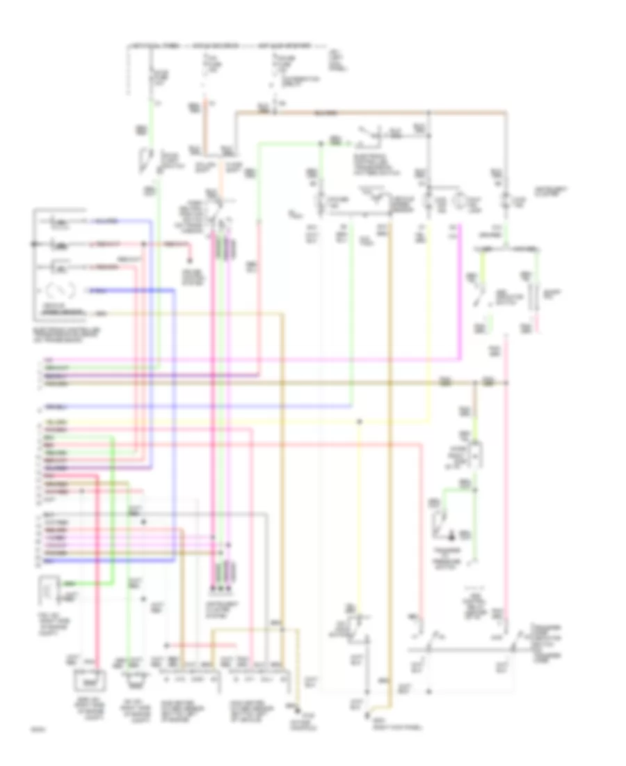
3.0L, Engine Performance Wiring Diagrams (1 of 2) for Toyota Pickup SR5 1994
List of elements for 3.0L, Engine Performance Wiring Diagrams (1 of 2) for Toyota Pickup SR5 1994:
- #10
- #20
- (camshaft
- (left
- (left front of engine)
- (left kick panel)
- (left side of engine compt)
- (right
- (right side of engine compt)
- (tachometer)
- +b1
- 4wd
- A/c
- A/t
- A/t 4wd
- Acc
- Act
- Acv
- Air
- Air condit- ioning system
- Alt fuse 80a
- Am1
- Am2
- Batt
- Bearing cap)
- Circuit opening relay (behind right side of i/p)
- Cluster system
- Coil
- Coil wire
- Conditioning
- Cruise control system
- Data link connector 1
- Distributor
- E21
- Efi fuse 15a
- Efi main relay
- Egr
- Egr gas temperature sensor (right side of engine)
- Engine control module (right kick panel)
- Engine coolant temperature sensor (center rear of engine)
- Eo1
- Eo2
- Fpu
- Fuel
- Fuel pump (in fuel tank)
- G100 fender)
- G117
- G200
- Hot at all times
- Hot in on or start
- Ht1
- Ht2
- Idl
- Ig-
- Ig2
- Igf
- Ign fuse 7.5a
- Igniter
- Ignition
- Ignition switch
- Igt
- Injectors
- Instrument
- J/b 1 (left kick panel)
- J/b 1 kick panel)
- Knk
- Knock sensor (top center of engine)
- Lock
- M/t
- Noise filter (left front engine compt)
- Od1
- Od2
- Oil
- Ox2
- Park/neutral position switch (on transmission) (closed in park and neutral)
- Pnk
- Pwr
- R/b 2 engine compt)
- Red
- Sel2
- Sp1
- Sp2
- St1
- Sta
- Start
- Starter relay
- Starting
- Starting system
- Stj
- Stp
- System
- Tha
- Thg
- Tho1
- Tho2
- Throttle position sensor (top center of engine)
- Thw
- Volume air flow meter (left front engine compt)
- Vta
- Wire
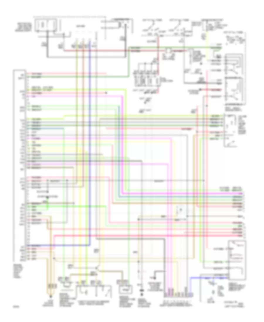
3.0L, Engine Performance Wiring Diagrams (2 of 2) for Toyota Pickup SR5 1994
List of elements for 3.0L, Engine Performance Wiring Diagrams (2 of 2) for Toyota Pickup SR5 1994:
- (a/t only)
- (a/t)
- (camshaft bearing cap)
- (m/t)
- (on trans- mission)
- (right kick panel)
- (right side
- (right side of i/p)
- 4wd ind.
- 4wd w/ a/t
- 4wd w/ m/t
- A/t
- A/t 4wd
- A/t oil temp. ind.
- A/t w/ 4wd only
- A/t w/ add
- Add control relay (center of i/p)
- Add indicator switch
- As vsv
- B10
- B12
- Cig fuse 15a
- Column shift
- Compt)
- Cruise control system
- D12
- Diode
- Egr vsv
- Electronic controlled transmission pattern switch (a/t only)
- Electronic controlled transmission solenoid (on transmission)
- Floor shift
- Fpu vsv
- G117
- G203
- Gauge fuse 10a
- Hot at all times
- Hot in acc or on
- Hot in on or start
- Ht1
- Instrument cluster
- Instrument cluster system
- Integration relay
- J/b 1 (left kick panel)
- M/t w/ add
- Main heated oxygen sensor (bottom left of vehicle)
- Malf. ind. lamp
- O/d main switch (a/t only)
- O/d off ind.
- Of engine
- Of engine compt)
- Oil temperature sensor (on transmission)
- Oxl1
- Oxr
- Park/ neutral position switch n
- Pnk
- Power ind.
- Red
- Short pin
- Stop fuse 15a
- Stop light switch
- Sub heated oxygen sensor (bottom left of vehicle) (california)
- Transfer case fluid temperature sensor (on transfer case)
- Transfer case indicator switch (on transfer case)
- Transfer oil pressure switch (a/t w/ add)
- Vehicle speed sensor
- W/ add
- W/ tach
- W/o add
- W/o tach