ENGINE PERFORMANCE
4.7L
4.7L, Engine Performance Wiring Diagrams (1 of 3) for Toyota Sequoia SR5 2002

List of elements for 4.7L, Engine Performance Wiring Diagrams (1 of 3) for Toyota Sequoia SR5 2002:
- (engine harn, center of engine)
- (i/p harn, behind right side of dash) i4
- (right rear of engine)
- (right rear of engine) eb
- A/t oil temperature sensor (on transmission)
- Accelerator position sensor (on throttle body)
- Camshaft position sensor (front of left cyl head)
- Cl+
- Cl-
- Conn e7
- Conn e8
- Crankshaft position sensor (lower front of engine)
- E01
- E02
- E03
- Engine control module (behind right side of dash)
- Engine coolant temperature sensor (right front of engine)
- Evg
- Fuel injectors
- Ge01
- Htl
- Htl2
- Htr
- Htr2
- Igf1
- Igf2
- Igniters & ignition coils
- Igt1
- Igt2
- Igt3
- Igt4
- Igt5
- Igt6
- Igt7
- Igt8
- Knkl
- Knkr
- Mass airflow meter (right front of eng compt)
- Me01
- Nca
- Ne+
- Ne-
- Noise filters
- Oxl1
- Oxl2
- Oxr1
- Oxr2
- Pnk
- Prg
- Red
- Tha
- Throttle control motor (left front of engine)
- Throttle position sensor (on throttle body)
- Thw
- Vapor pressure sensor (under rear of vehicle)
- Vpa
- Vpa2
- Vta
- Vta2
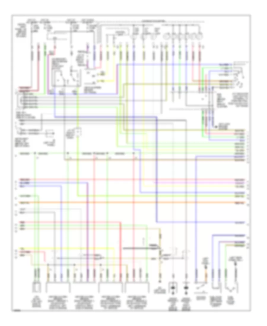
4.7L, Engine Performance Wiring Diagrams (2 of 3) for Toyota Sequoia SR5 2002
List of elements for 4.7L, Engine Performance Wiring Diagrams (2 of 3) for Toyota Sequoia SR5 2002:
- (left kick panel) ie
- (left rear wheelwell) bi
- (on bracket, above brake pedal) stoplight switch
- A/t indicator light switch (integral to park/neutral position switch) (on trans)
- A/t oil temp
- A10
- A12
- A20
- Anti-lock brakes system
- C10
- Combination meter
- Control unit
- D12
- E18
- Ec (left side of engine)
- F10
- Fuel pump (in fuel tank)
- Fuel pump resistor (left rear of engine compt)
- Gauge fuse 10a
- Heated oxygen sensor (bank 1 sensor 1) (on exhaust manifold, left side of engine)
- Heated oxygen sensor (bank 1 sensor 2) (on exhaust pipe, left underside of vehicle)
- Heated oxygen sensor (bank 2 sensor 1) (on exhaust manifold, right side of engine)
- Heated oxygen sensor (bank 2 sensor 2) (on exhaust pipe, right underside of vehicle)
- Hot at all times
- Hot in run or start
- Ie (left kick panel)
- Ig+
- Ign2 fuse 20a
- Instru- ment panel j/b (behind left end of dash)
- Instrument panel j/b (behind left end of dash)
- Ipo
- J/c 15 (right end of dash)
- J/c 16 (right end of dash)
- Knock sensor 1 (top right side of engine)
- Knock sensor 2 (top left side of engine)
- Malf ind lamp
- Nca
- O/d main switch
- O/d off ind
- Red
- Stop fuse 15a
- Sub j/b 3 (behind right side of cluster)
- Sub j/b 4 (behind right side of cluster)
- Tail fuse 15a
- Vehicle speed sensor (on trans)
- Vsv (evap) (top left side of engine)
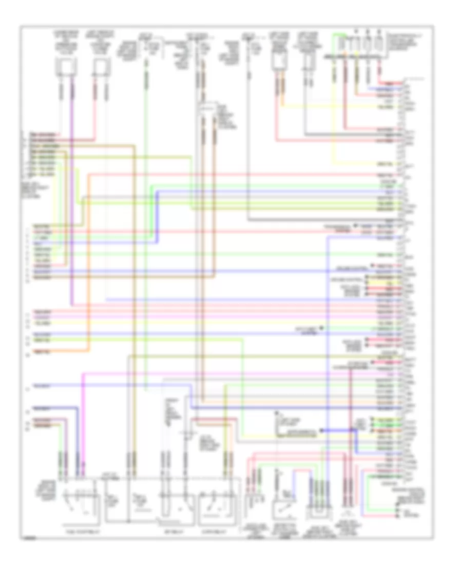
4.7L, Engine Performance Wiring Diagrams (3 of 3) for Toyota Sequoia SR5 2002
List of elements for 4.7L, Engine Performance Wiring Diagrams (3 of 3) for Toyota Sequoia SR5 2002:
- (2wd)
- (4wd)
- (front of left front fender) ed
- (left rear of engine compt) vsv (canister closed valve)
- (left side of trans) o/d direct clutch speed sensor
- (left side of trans) vehicle speed sensor
- (under rear of vehicle) vsv (pressure switching valve)
- +b1
- +bm
- A/c system
- A10
- A12
- A13
- Ac1
- Act
- Anti- theft system
- Anti-lock brakes system
- Anti-theft system
- Batt
- C/opn relay
- Ccs
- Ccv
- Code
- Conn e4
- Conn e5
- Conn e6
- Cruise control
- D10
- Data link connector 3 (left of dash)
- Detection switch (l4) (on transfer case)
- E10
- E17
- Efi 1 fuse 20a
- Efi 2 fuse 10a
- Efi relay
- Electronically controlled transmission solenoid
- Els
- Eng+
- Eng-
- Engine control module (behind right side of dash)
- Engine room j/b (left side of engine compt)
- Engine room r/b 2 (left side of engine compt)
- Etcs fuse 15a
- F/ps
- Fpr
- Fuel pump relay
- Hot at all times
- Hot in run or start
- Hot in start
- If (left side of dash)
- Ign 1 fuse 10a
- Igsw
- Imld
- Instrument panel j/b (behind left end of dash)
- J/c 16 (behind right end of dash)
- Mrel
- Nco+
- Nco-
- Neo
- Nsw
- Odlp
- Odms
- Oil
- Oilw
- Pnk
- Ptnk
- Red
- Rxck
- Sil
- Slt
- Slt+
- Slt-
- Sp2+
- Sp2-
- Spd
- St1-
- Sta
- Sta fuse 7.5a
- Starting/ charging system
- Stp
- Sub j/b 3 (behind right side of cluster)
- Sub j/b 4 (behind right side of cluster)
- Tach
- Tbp
- Thwo
- Transmission system
- Trc+
- Txct
- Wfse