ENGINE PERFORMANCE
4.7L
4.7L, Engine Performance Wiring Diagram (1 of 4) for Toyota Sequoia SR5 2004

List of elements for 4.7L, Engine Performance Wiring Diagram (1 of 4) for Toyota Sequoia SR5 2004:
- (at rear of left cylinder head)
- (dash harn behind right side of dash)
- (engine harn, top mid rear of engine)
- Accr
- Air conditioning system
- Camshaft position sensor (front of left cylinder head)
- Ccv
- Crankshaft position sensor (lower front of engine)
- Detection switch (l4)
- E01
- E02
- E03
- E2g
- Eb (rear of right cly head)
- Engine control module (behind right side of dash)
- Engine coolant temperature sensor (right front of engine)
- Fpr
- Fuel injectors
- G2+
- G2-
- Ge01
- Igf1
- Igf2
- Igniters & ignition coils
- Igt1
- Igt2
- Igt3
- Igt4
- Igt5
- Igt6
- Igt7
- Igt8
- J/c 42
- J/c j18 (behind right end of dash)
- Lck1
- Mass airflow meter (right front of eng compt)
- Me01
- Nca
- Ne+
- Ne-
- Nsw
- Pnk
- Prg
- Red
- Sta
- Starting/charging system
- Stsw
- Sub j/b 3 (behind right side of cluster)
- Tfn
- Tha
- Throttle control motor & position sensor (on throttle body assembly)
- Thw
- Transmission system
- Vta1
- Vta2
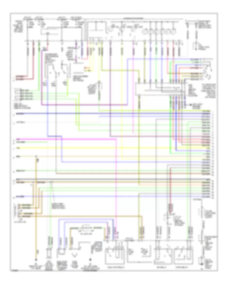
4.7L, Engine Performance Wiring Diagram (2 of 4) for Toyota Sequoia SR5 2004
List of elements for 4.7L, Engine Performance Wiring Diagram (2 of 4) for Toyota Sequoia SR5 2004:
- (dash harn behind right side of dash)
- (on bracket, above brake pedal) stoplight switch
- A/t indicator light switch (integral to park/neutral position switch) (on trans)
- A/t oil temp
- Anti-lock brakes system
- Bi (at left side of room partition crossmember)
- C/opn relay
- C10
- Combination meter
- D10
- D12
- E18
- Ec (rear of left cyl head)
- Efi 1 fuse 20a
- Efi 2 fuse 10a
- Efi relay
- Engine room j/b (left side of engine compt)
- F10
- Fuel pump (in fuel tank)
- Fuel pump relay
- Fuel pump resistor (left rear of engine compt)
- Gauge fuse 10a
- Hot at all times
- Hot in run or start
- Ie (left kick panel)
- Ign2 fuse 20a
- Instru- ment panel j/b (behind left end of dash)
- Instrument panel j/b (behind left end of dash)
- Ipo
- J/c 35 (right end of dash)
- J/c j14 & j15 (behind right end of dash)
- J/c j28 (left side of eng compt)
- J/c j28 (on left side of engine compt)
- J/c j35 & j36
- J/c j48 & j49
- J/c j8 (behind left end of dash)
- J14
- J15
- J35
- J36
- J48
- J49
- Malf ind lamp
- O/d off ind
- Stop fuse 15a
- Sub j/b 3 (behind right side of cluster)
- Sub j/b 4 (behind right side of cluster)
- Tail fuse 15a
- Vehicle speed sensor (on trans)
- Vsv (evap) (top left side of engine)
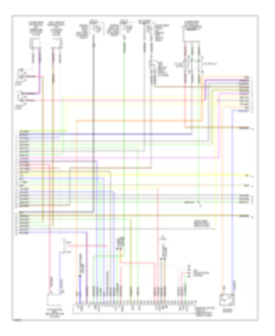
4.7L, Engine Performance Wiring Diagram (3 of 4) for Toyota Sequoia SR5 2004
List of elements for 4.7L, Engine Performance Wiring Diagram (3 of 4) for Toyota Sequoia SR5 2004:
- (dash harn behind right side of dash)
- (left rear of engine compt) vsv (canister closed valve)
- (under rear of vehicle) vapor pressure sensor
- (under rear of vehicle) vsv (pressure switching valve)
- +bm
- 2wd
- 4wd
- 4wd control ecu (behind center of dash)
- A/cs
- Acld
- Acmg
- Air conditioning system
- Ccs
- Cruise control
- E17
- Engine control module (behind right side of dash)
- Engine room j/b (left side of engine compt)
- Engine room r/b 2 (left side of engine compt)
- Etcs fuse 15a
- F11
- Hot in run or start
- Hot in start
- Ign 1 fuse 10a
- Imi
- Imo
- Instrument panel j/b (behind left end of dash)
- J/c j46 & j47
- J/c j48 & j49
- J/e j44 & j45
- J/e j48 & j49
- J44
- J45
- J46
- J47
- J48
- J49
- J49 e
- O/d main switch
- Odlp
- Oilw
- Spd
- St1-
- Sta fuse 7.5a
- Stp
- Sub j/b 4 (behind right side of cluster)
- System
- System anti-theft
- The
- Thwo
- W/ 4wd
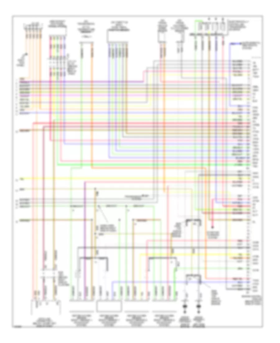
4.7L, Engine Performance Wiring Diagram (4 of 4) for Toyota Sequoia SR5 2004
List of elements for 4.7L, Engine Performance Wiring Diagram (4 of 4) for Toyota Sequoia SR5 2004:
- (above right kick panel) translate ecu
- (dash harn behind right side of dash)
- (eng harn, top middle rear of engine)
- (on throttle body) accel pedal position sensor
- (on trans) o/d direct clutch speed sensor
- (on trans) vehicle speed sensor
- (on transmission)
- +b2
- 4wd
- A/t oil temperature sensor
- A17
- Batt
- Data link connector 3 (below lower left side of dash)
- Electronically controlled transmission solenoid
- Els
- Eng+
- Eng-
- Engine control module (behind right side of dash)
- Eom
- Epa
- Epa2
- F/ps
- Heated oxygen sensor (bank 1 sensor 1) (on exhaust system)
- Heated oxygen sensor (bank 1 sensor 2) (on exhaust system)
- Heated oxygen sensor (bank 2 sensor 1) (on exhaust system)
- Heated oxygen sensor (bank 2 sensor 2) (on exhaust system)
- Ht1a
- Ht1b
- Ht2a
- Ht2b
- Ig (at right kick panel)
- Igsw
- J/c j14 & j15 (behind right end of dash)
- J/c j43
- J14
- J15
- Knk1
- Knk2
- Knock sensor 1 (top right side of engine)
- Knock sensor 2 (top left side of engine)
- Mrel
- Nca
- Nco+
- Nco-
- Neo
- Odms
- Ox1a
- Ox1b
- Ox2a
- Ox2b
- Pnk
- Ptnk
- Red
- Sil
- Slt
- Slt+
- Slt-
- Sp2+
- Sp2-
- Star
- Starting/ charging system
- Sub j/b 4 (behind right side of cluster)
- Tach
- Tbp
- Thoc
- Transmission system
- Trc+
- Trc-
- Vcp2
- Vcpa
- Vpa
- Vpa2
- Wfse