ENGINE PERFORMANCE
3.3L
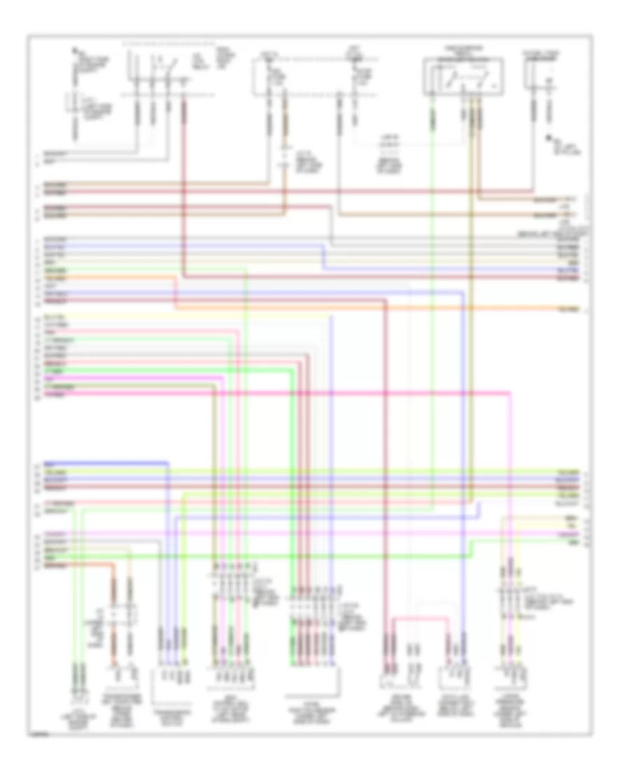
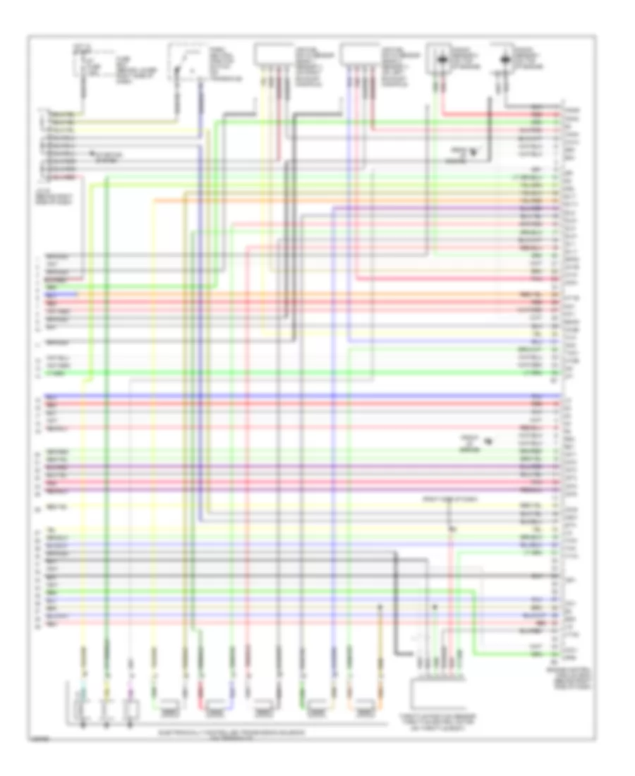
3.3L, Engine Performance Wiring Diagram (1 of 6) for Toyota Sienna CE 2005

List of elements for 3.3L, Engine Performance Wiring Diagram (1 of 6) for Toyota Sienna CE 2005:
- (behind left end of dash)
- (behind left side of dash)
- (left center of dash)
- +b2
- +bm
- A/c system
- A/f fuse 25a
- Acmg
- Batt
- C/ opn relay
- Ccs
- Computer data lines system
- Cruise control system
- Ed (left side of engine compt)
- Efi 1 fuse 20a
- Efi 2 fuse 10a
- Efi relay
- Els
- Eng+
- Eng-
- Engine control module (ecm) (behind right side of dash)
- Engine room j/b (on left side of engine compt)
- Eom
- Epa
- Epa2
- Etcs fuse 10a
- Hot at all times
- Igsw
- Imi
- Imo
- Inverter relay
- J/c 18
- J/c 21
- J/c 3 & j/c 4
- J/c 3 & j/c 4 (behind left end of dash)
- J/c 5 & j/c 6 (behind left end of dash)
- J/c3
- J/c4
- J/c5
- J/c6
- Mpx1
- Mpx2
- Mrel
- Neo
- Pnk
- Ptnk
- Red
- Sil
- Spd
- St1-
- Stp
- Tach
- Tam
- Trc+
- Trc-
- Vca2
- Vcp2
- Vpa
- Vpa2
- Wfse
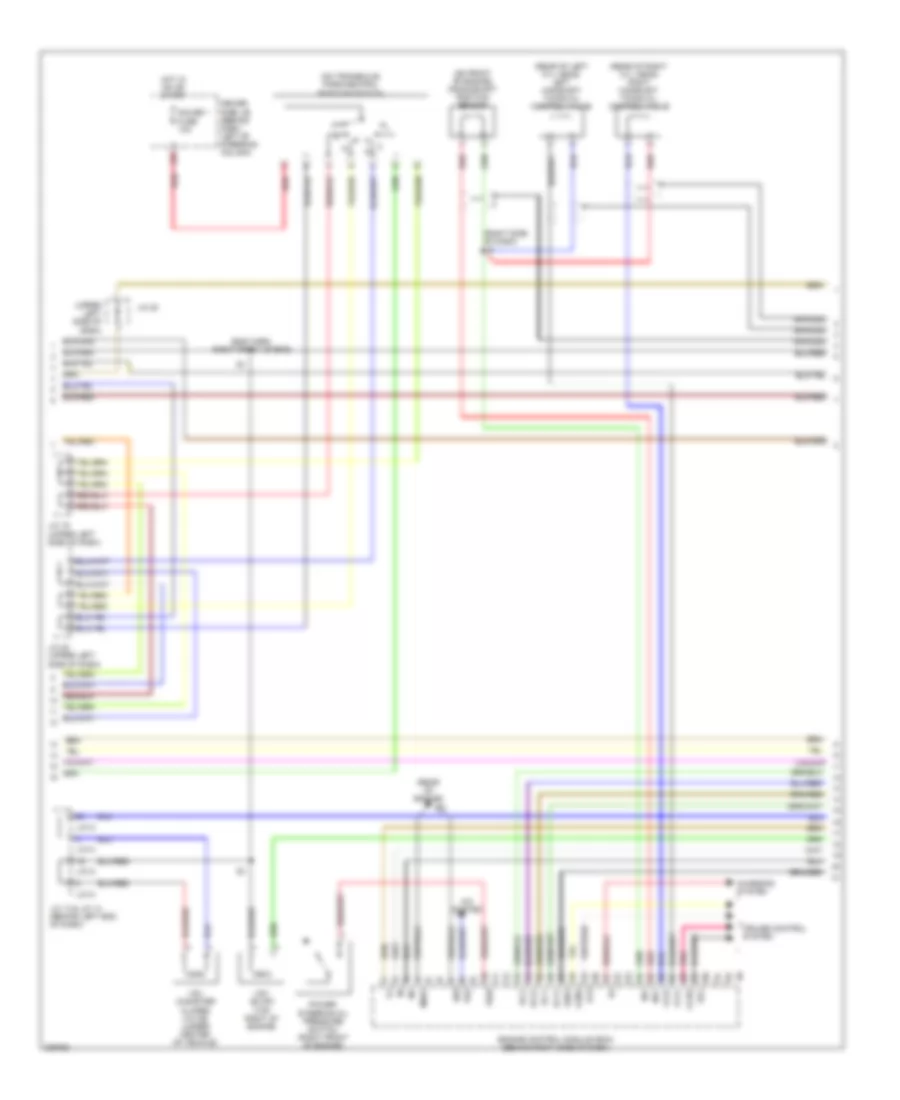
3.3L, Engine Performance Wiring Diagram (2 of 6) for Toyota Sienna CE 2005
List of elements for 3.3L, Engine Performance Wiring Diagram (2 of 6) for Toyota Sienna CE 2005:
- (above brake pedal) stoplight switch
- (behind left side of dash)
- (in fuel tank) fuel pump
- A/f htr relay
- Accel position sensor (under left side of dash)
- At4
- Atl
- Bh (at left "b" pillar)
- C16
- Compt)
- Data link connector 3 (below left side of dash)
- Driver side j/b (behind dash, left of steering column)
- Efii
- Efio
- Eng+
- Eng-
- H12
- H13
- H34
- Hot at all times
- Hot in on
- Ign fuse 7.5a
- J/c (upper left side of dash)
- J/c 1 (left side of engine compt)
- J/c 13 & j/c 14 (behind left end of dash)
- J/c 15
- J/c 18 (behind left side of dash)
- J/c 2 (left side of engine compt)
- J/c 5 & j/c 6 (behind left end of dash)
- J/c13
- J/c14
- J/c3
- J/c4 j/c 3 & j/c 4 (behind left end of dash)
- J/c5
- J/c6
- K14
- K28
- K30
- Neo
- Nssd
- Nssl
- Pnk
- Ptnk
- R/b 6 (in eng room j/b)
- Sil
- Skid control ecu w/ actuator (left rear of eng compt)
- Stop fuse 10a
- Transmission control switch
- Transponder key computer (behind upper center of dash)
- Trc+
- Trc-
- Vapor pressure sensor (under left side of vehicle)
- Vcc
- Wfse
3.3L, Engine Performance Wiring Diagram (3 of 6) for Toyota Sienna CE 2005
List of elements for 3.3L, Engine Performance Wiring Diagram (3 of 6) for Toyota Sienna CE 2005:
- (eng harn, right front of eng)
- (on front of engine) crankshaft position sensor
- (on transaxle) park/neutral position switch
- (rear of engine)
- (rear of left cyl head) left camshaft timing oil control valve
- (rear of right cyl head) right camshaft timing oil control valve
- (right side of dash)
- (upper left side of dash)
- A/c system
- Braided
- Cchg
- Charging system
- Cruise control system
- Driver side j/b (behind dash, left of steering column)
- E03
- Elc
- Engine control module (ecm) (behind right side of dash)
- Gauge 1 fuse 10a
- Ge01
- Hot in on or start
- J/c 13 & j/c 14 (behind left end of dash)
- J/c 19 (upper left side of dash)
- J/c 20
- J/c 20 (upper left side of dash)
- J/c13
- J/c14
- L26
- Lcs
- Lgnd
- Me01
- Ne+
- Ne-
- Oc1+
- Oc1-
- Oc2+
- Oc2-
- Pnk
- Power steering oil pressure switch (right front of engine)
- Pr2
- Psw
- Red
- Vsv (canister closed valve) (under center of vehicle)
- Vsv (evap) (top right of engine)
- Vv1+
- Vv2+
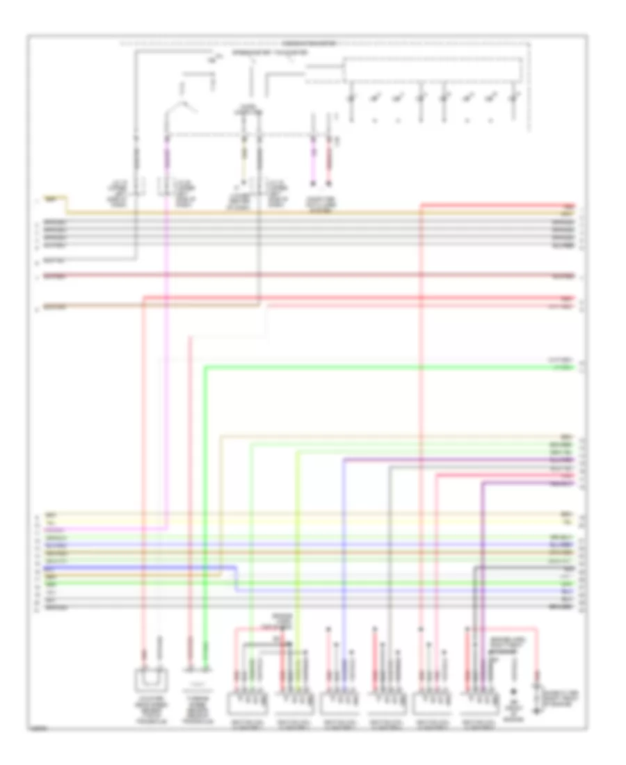
3.3L, Engine Performance Wiring Diagram (4 of 6) for Toyota Sienna CE 2005
List of elements for 3.3L, Engine Performance Wiring Diagram (4 of 6) for Toyota Sienna CE 2005:
- (engine harn, right front of engine)
- (engine harn, top of eng)
- (lower center of dash)
- Braided
- C10
- Combination meter
- Computer data lines system
- Counter gear speed sensor (top of transaxle)
- Eb (front of engine)
- Gnd
- Igf
- Ignition coil & igniter 1
- Ignition coil & igniter 2
- Ignition coil & igniter 3
- Ignition coil & igniter 4
- Ignition coil & igniter 5
- Ignition coil & igniter 6
- Igt
- J/c 19 (upper left side of dash)
- J/c 20 (upper left side of dash)
- Micro computer
- Mil
- Noise filter (right front of engine)
- Pnk
- Red
- Speedometer
- Tachometer
- Turbine speed sensor (rear of transaxle)
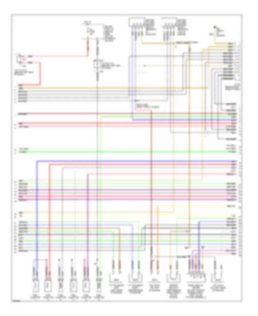
3.3L, Engine Performance Wiring Diagram (5 of 6) for Toyota Sienna CE 2005
List of elements for 3.3L, Engine Performance Wiring Diagram (5 of 6) for Toyota Sienna CE 2005:
- (eng harn, right front of eng)
- (right side of dash)
- Braided
- Driver side j/b (behind dash, left of steering column)
- E2g
- Eb (front of engine)
- Engine coolant temp sensor (right front top of engine)
- Fuel injector
- H18
- H19
- Heated oxygen sensor (bank 1 sensor 2) (top of engine)
- Heated oxygen sensor (bank 2 sensor 2) (in exhaust)
- Hot in on
- Inj fuse 15a
- J/c 29 (behind right side of dash)
- J/c 3 & j/c 4 (behind left end of dash)
- J/c3
- J/c4
- Mass airflow meter (on left side of engine compt, part of air intake assembly)
- Pnk
- Red
- Tha
- Vsv (acis) (on top of engine)
- Vsv (aicv) (on left rear of engine)
- Vvt solenoid left (left rear of engine)
- Vvt solenoid right (center rear of engine)
3.3L, Engine Performance Wiring Diagram (6 of 6) for Toyota Sienna CE 2005
List of elements for 3.3L, Engine Performance Wiring Diagram (6 of 6) for Toyota Sienna CE 2005:
- (front of engine)
- (rear ec of engine)
- (right side of dash)
- A1a+
- A1a-
- A2a+
- A2a-
- Acis
- Aicv
- Air fuel ratio sensor (bank 1 sensor 1) (on right exhaust manifold)
- Air fuel ratio sensor (bank 2 sensor 1) (on left exhaust manifold)
- Braided
- Ccv
- Dsl
- E01
- E02
- E04
- E05
- E2g
- Ekn2
- Eknk
- Electronically controlled transmission solenoid (on transaxle)
- Engine control module (ecm) (behind right side of dash)
- Fuse box (behind lower right side of dash)
- Ha1a
- Ha2a
- Hot in start
- Ht1b
- Ht2b
- Igf1
- Igt1
- Igt2
- Igt3
- Igt4
- Igt5
- Igt6
- J/c 30 (behind right side of dash)
- Knk2
- Knkr
- Knock sensor 1 (on top of engine)
- Knock sensor 2 (on top of engine)
- Nc+
- Nc-
- Nsw
- Nt+
- Nt-
- Ox1b
- Ox2b
- P/n
- Park/ neutral position switch (on transaxle)
- Pnk
- Prg
- Red
- Sl1+
- Sl1-
- Sl2+
- Sl2-
- Sl3+
- Sl3-
- Slt+
- Slt-
- St fuse 7.5a
- Sta
- Starting system
- Tha
- Tho1
- Throttle position sensor/ throttle control motor (on throttle body)
- Thw
- Vta1
- Vta2