ENGINE PERFORMANCE
2.7L
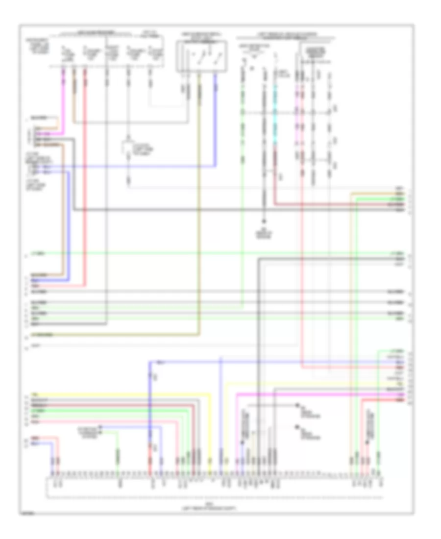
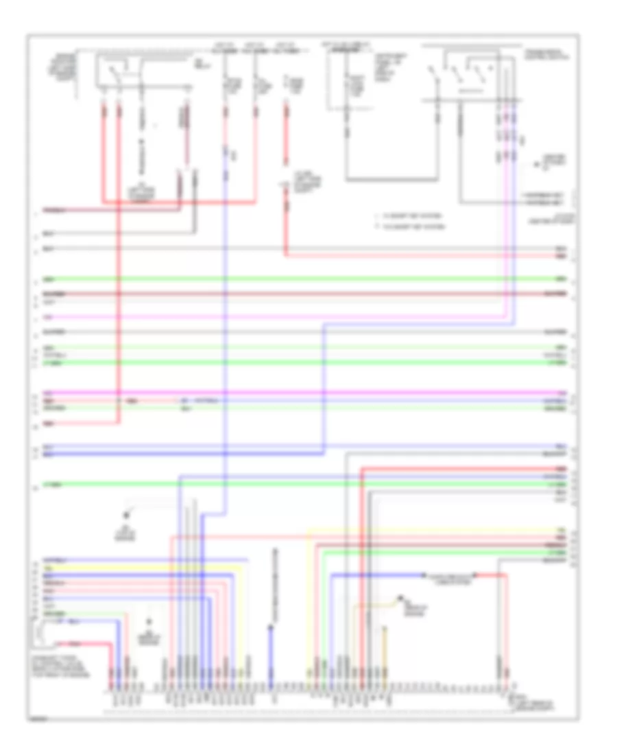
2.7L, Engine Performance Wiring Diagram (1 of 4) for Toyota Sienna XLE 2012

List of elements for 2.7L, Engine Performance Wiring Diagram (1 of 4) for Toyota Sienna XLE 2012:
- (fuel pump: fuel tank assembly) fuel pump & fuel sender gauge assembly
- (left side of engine compt)
- (under left front seat) k1
- +b2
- +bm
- A/f fuse 20a
- A/f htr relay
- A2 (left side of engine compt)
- A30
- A46
- A55
- Accelerator position sensor (accelerator pedal assembly)
- Ad4
- Anti-theft system
- Ba2
- Batt
- C/opn relay
- Camshaft timing oil control valve (bank 1 exhaust side) (top front of engine)
- Camshaft timing oil control valve (bank 1 intake side) (top front of engine)
- Canh
- Canl
- Ccs
- Computer data lines system
- Cooling fans system
- Cruise control system
- D7 (center of dash)
- Ecm (left rear of engine compt)
- Ect fuse 7.5a
- Efi 1 fuse 25a
- Efi 2 fuse 10a
- Efi main relay
- Engine room r/b (left side of engine compt)
- Epa
- Epa2
- Etcs fuse 10a
- F34
- Gauge
- Hot at all times
- Igsw
- Imi
- Imo
- Instrument cluster system
- Instrument panel j/b (left side of dash)
- J/c a46 & b44 (left side of engine compt) b44
- J/c a46 (left side of engine compt)
- J/c a49
- J/c b44 (left side of engine compt)
- J/c d105 (center of dash)
- Ka2
- Mpmp
- Mrel
- Park/neutral position switch assembly (transaxle assembly)
- Pnk
- Pump
- Red
- Rfl
- Sftd
- Sftu
- Spd
- St-
- Sta
- Starting/charging system
- Stp
- Tach
- Transmission control ecu assembly (left front of engine compt)
- Transmission control switch
- Vcp2
- Vcpa
- Vpa
- Vpa2
- Vpmp
- Gk1
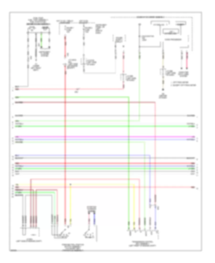
2.7L, Engine Performance Wiring Diagram (2 of 4) for Toyota Sienna XLE 2012
List of elements for 2.7L, Engine Performance Wiring Diagram (2 of 4) for Toyota Sienna XLE 2012:
- (above brake pedal) stop light switch assembly
- (left rear of vehicle chassis)
- A44
- A55
- Acis
- Ad4
- Aicv
- Alt
- B4 (rear of engine)
- B45
- B5 (rear of engine)
- Ba1
- Ba2
- Can+
- Can-
- Canister pressure sensor
- Canister pump module
- Computer data lines system
- E04
- Ecm (left rear of engine compt)
- F26
- F29
- F35
- F36
- Gauge 1 fuse 10a
- Gauge 2 fuse 7.5a
- Ge01
- Ha1a
- Hot at all times
- Hot in on or start
- Ht1b
- Ia1+
- Ia1-
- Ig2 fuse 7.5a
- Igf1
- Instrument panel j/b (left side of dash)
- J/c a46 (left side of engine compt)
- J/c a48 (left side of dash)
- J/c d100 (left side of dash)
- Ka2
- Leak detection pump
- Lines system computer data
- Me01
- Mgnd
- Mtrb
- Nsw
- Oc1+
- Oc1-
- Oe1+
- Oe1-
- Pbv
- Pnk
- Prg
- Red
- Sgnd
- Shift lock fuse 7.5a
- Starting/ charging system
- Stop fuse 10a
- Vcc
- Vent valve
- Vgnd
- Vlvb
- Vout
- Gk2
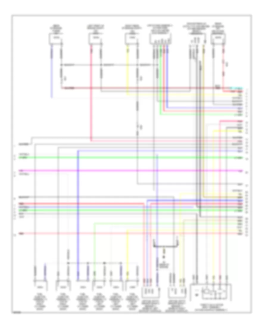
2.7L, Engine Performance Wiring Diagram (3 of 4) for Toyota Sienna XLE 2012
List of elements for 2.7L, Engine Performance Wiring Diagram (3 of 4) for Toyota Sienna XLE 2012:
- (intake manifold assembly) throttle w/ motor body assembly
- A/t/odo lcd
- A/t/odo/acc lcd
- A2 (left front of engine compt)
- A46
- Ad4
- Anti-lock brakes system
- B4 (rear of engine)
- B44
- Ba1
- Ba2
- Buzzer
- Bf2
- Canh
- Canl
- Chk
- Combination meter assembly
- Computer data lines system
- D6 (center of dash)
- Dome fuse 7.5a
- Engine room r/b (left side of engine compt)
- Except option meter
- Hot at all times
- Ig+
- Ig2
- Ig2 relay
- Ind lamp malfunction
- Inj fuse 25a
- J/c a46 & b44 (left side of engine compt)
- J/c a52 (left side of engine compt)
- J/c d96 (left side of dash)
- J/c d99 (left side of dash)
- Knock control sensor (bank 1) (rear of engine)
- Micro processor
- Nca
- Option meter
- Pnk
- Purge vsv (rear of engine compt)
- Red
- Vsv (acis) (right rear of engine compt)
- Vsv (air intake control) (rear of engine)
- Vsv (ejector) (rear of engine compt)
- Vta
- Vta2
- W/ smary key system
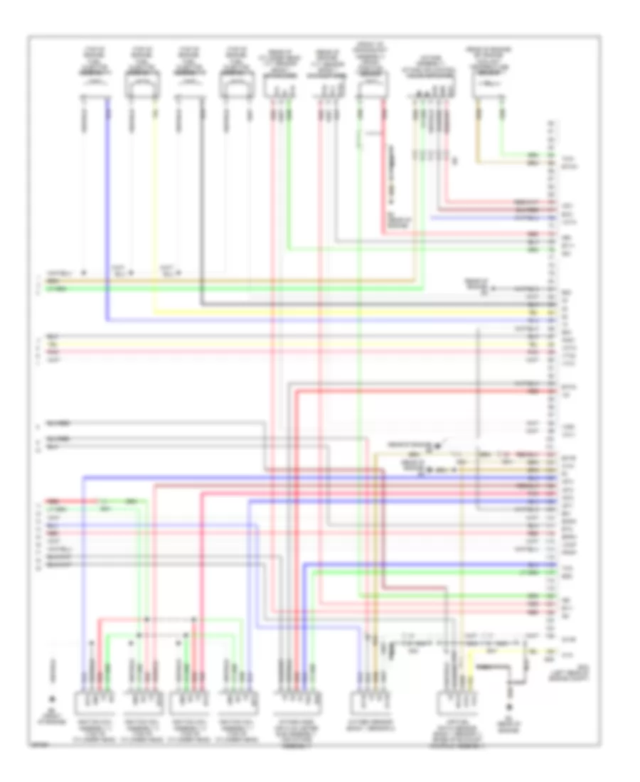
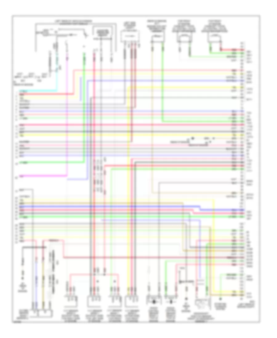
2.7L, Engine Performance Wiring Diagram (4 of 4) for Toyota Sienna XLE 2012
List of elements for 2.7L, Engine Performance Wiring Diagram (4 of 4) for Toyota Sienna XLE 2012:
- (front of crankshaft assembly) crank position sensor
- (front of engine)
- (intake assembly) intake air control valve actuator
- (rear of cylinder head) vvt sensor (bank 1 intake side)
- (rear of engine) b4
- (rear of engine) b5
- (rear of engine) efi engine coolant temperature sensor
- (rear of engine) vvt sensor (bank 1 exhaust side)
- (top of engine) fuel injector assembly 1
- (top of engine) fuel injector assembly 2
- (top of engine) fuel injector assembly 3
- (top of engine) fuel injector assembly 4
- A1a+
- A1a-
- Ad4
- Air fuel ratio sensor (bank 1 sensor 1) (base of exhaust manifold assembly)
- B4 (rear of engine)
- B45
- Ba1
- Ba2
- Ba6
- Bf2
- E01
- E02
- E03
- E2g
- Ecm (left rear of engine compt)
- Eia1
- Eknk
- Eppm
- Eta
- Etha
- Ethw
- Ev1+
- Ev1-
- Ex1b
- G2+
- G2-
- Gnd
- Ht1b
- Iac1
- Igf
- Ignition coil assembly 1 (top of cylinder head)
- Ignition coil assembly 2 (top of cylinder head)
- Ignition coil assembly 3 (top of cylinder head)
- Ignition coil assembly 4 (top of cylinder head)
- Igt1
- Igt2
- Igt3
- Igt4
- Intake mass air flow meter sub assembly (air intake assembly)
- Knk1
- Nca
- Ne+
- Ne-
- Out
- Ox1b
- Oxygen sensor (bank 1 sensor 2)
- Pnk
- Ppmp
- Red
- Tha
- Thw
- Vc2
- Vccp
- Vce1
- Vcta
- Vcv1
- Vdd
- Vta1
- Vta2
- Vve+
- Vve-
- Vvi+
- Vvi-
3.5L
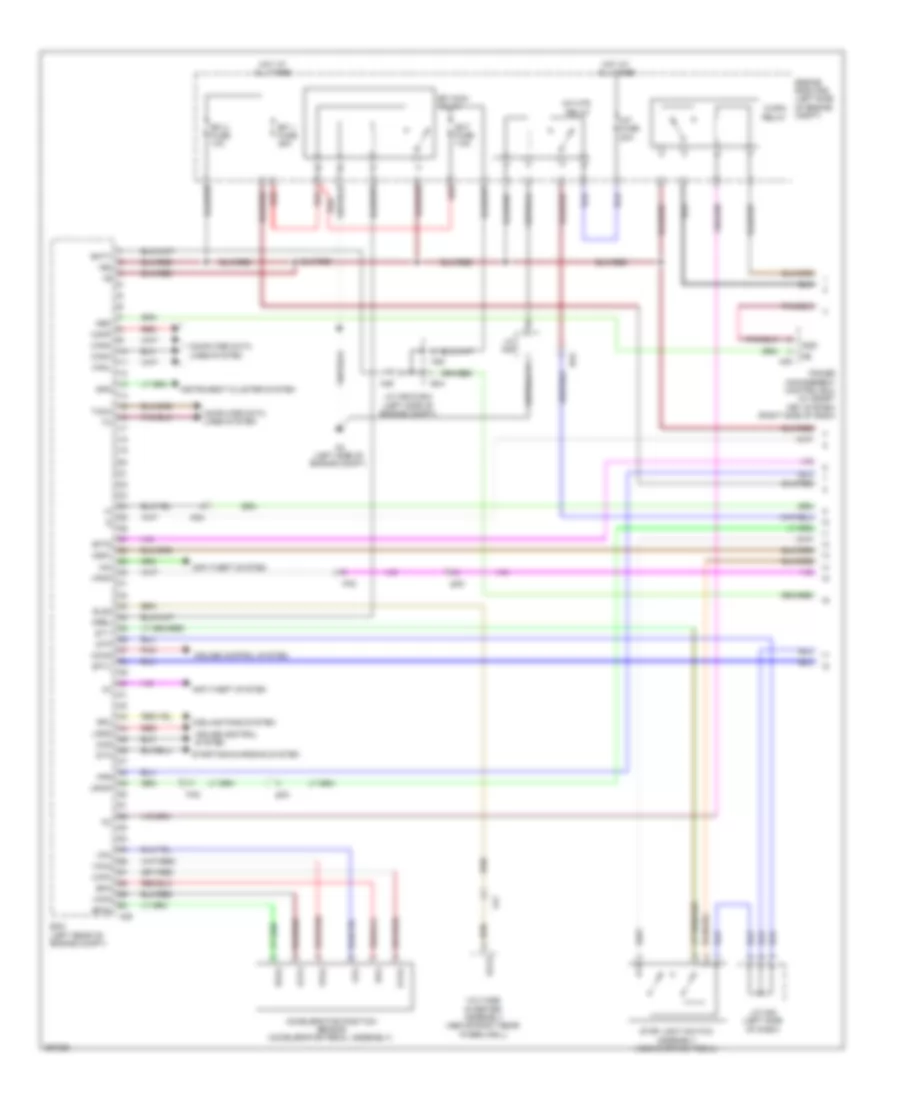
3.5L, Engine Performance Wiring Diagram (1 of 6) for Toyota Sienna XLE 2012
List of elements for 3.5L, Engine Performance Wiring Diagram (1 of 6) for Toyota Sienna XLE 2012:
- +b2
- A/f fuse 20a
- A/f htr relay
- A2 (left side of engine compt)
- A35
- A39
- A46
- Accelerator position sensor (accelerator pedal assembly)
- Ad4
- Anti-theft system
- B44
- Ba2
- Batt
- Canh
- Canl
- Cann
- Canp
- Cchg
- Ccs
- Compt)
- Computer data lines system
- Cooling fans system
- Cruise control system
- Ecm (left rear of engine compt)
- Ect fuse 7.5a
- Efi 1 fuse 25a
- Efi 2 fuse 10a
- Efi main relay
- Els2
- Engine room r/b (left side of engine c/opn relay
- Epa
- Epa2
- Excd
- Fpr
- Hot at all times
- Ig2d
- Igsw
- Imi
- Imo
- Instrument cluster system
- J/c a46 & b44 (left side of engine compt)
- J/c a48 (left side of dash)
- J/c a49
- Ka2
- La1
- Lgnd
- Mpmp
- Mrel
- Neo
- Pnk
- Power management control ecu (w/ smart key system) (right side of dash)
- Red
- Rfc
- Sftd
- Sftu
- Spd
- St1-
- Sta
- Starting/charging system
- Stop light switch assembly (above brake pedal)
- Stp
- Tach
- Vcp2
- Vcpa
- Voltage inverter assembly (above right rear wheelwell)
- Vpa
- Vpa2
- Vpmp
- Gk2
3.5L, Engine Performance Wiring Diagram (2 of 6) for Toyota Sienna XLE 2012
List of elements for 3.5L, Engine Performance Wiring Diagram (2 of 6) for Toyota Sienna XLE 2012:
- (left rear of engine compt) fuel pump resistor
- (left side of engine compt) engine room r/b
- (left side of engine compt) j/c a46 & b44
- (left side of engine compt) j/c a50
- A14
- A46
- Acc
- Ad2
- B1 (rear of engine)
- B44
- Ba1
- Camshaft timing oil control valve (bank 2 exhaust side) (top front of engine)
- F29
- F35
- F36
- Fuel pmp relay
- Gnd
- Hot at all times
- Ig2 fuse 7.5a
- Igf
- Ignition coil assembly 1 (top of right cylinder bank)
- Ignition coil assembly 2 (top of left cylinder bank)
- Ignition coil assembly 3 (top of right cylinder bank)
- Ignition coil assembly 4 (top of left cylinder bank)
- Ignition coil assembly 5 (top of right cylinder bank)
- Ignition coil assembly 6 (top of left cylinder bank)
- Ignition or starter switch assembly
- Igt1
- Igt2
- Igt3
- Igt4
- Igt5
- Igt6
- Instrument panel j/b (left side of dash)
- Lock
- Off
- Pnk
- Red
- Run
- Start
- Stop fuse 10a
- W/ smart key system
- W/o smart key system
3.5L, Engine Performance Wiring Diagram (3 of 6) for Toyota Sienna XLE 2012
List of elements for 3.5L, Engine Performance Wiring Diagram (3 of 6) for Toyota Sienna XLE 2012:
- (center of dash) d7
- +bm
- A2 (left side of engine compt)
- A44
- Ad4
- Alt
- B2 (rear of engine)
- B3 (top of engine)
- Ba1
- Ba2
- Camshaft timing oil control valve (bank 2 intake side) (top front of engine)
- Can+
- Can-
- Computer data lines system
- Dome fuse 7.5a
- Ecm (left rear of engine compt)
- Engine room r/b (left side of engine compt)
- Eo1
- Eo2
- Eo3
- Eo4
- Eo5
- Etcs fuse 10a
- Ge01
- Ha1a
- Ha2a
- Hot at all times
- Hot w/ ig1 2 relay energized
- Ht1b
- Ht2b
- Ig2 relay
- Igt1
- Igt2
- Igt3
- Igt4
- Igt5
- Igt6
- Inj fuse 25a
- Instrument panel j/b (left side of dash)
- J/c a52 (left side of engine compt)
- J/c d105 (center of dash)
- Oc2+
- Oc2-
- Oe2+
- Oe2-
- Pnk
- Red
- Shift lock fuse 7.5a
- Starting/charging system
- Transmission control switch
- W/ smart key system
- W/o smart key system
3.5L, Engine Performance Wiring Diagram (4 of 6) for Toyota Sienna XLE 2012
List of elements for 3.5L, Engine Performance Wiring Diagram (4 of 6) for Toyota Sienna XLE 2012:
- (fuel pump: fuel tank assembly) fuel pump & fuel sender gauge assembly
- A/t/odo lcd
- A46
- A55
- Ad4
- Ba2
- Batt
- Buzzer
- Combination meter assembly
- Computer data lines system
- D6 (center of dash)
- Except optitron meter
- F26
- Gauge
- Gauge 1 fuse 10a
- Gauge 2 fuse 7.5a
- Hot in on or start
- Hot w/ ig1 1 relay energized
- Ig2
- Igsw
- Instrument cluster system
- Instrument panel j/b (left side of dash)
- J/c a46 & b44 (left side of engine b44 compt)
- J/c b44 (left side of engine compt)
- J/c d100 (left side of dash)
- J/c d96 (left side of dash)
- J/c d99 (left side of dash)
- K1 (under left front seat)
- Ka2
- Lcd (a/t/odo lcd)
- Malfunction ind lamp
- Micro processor
- Optitron meter
- Park/neutral position switch assembly (w/o smart key) (transaxle assembly)
- Pnk
- Pump
- Red
- Starting/ charging system
- Stp
- Transmission control ecu assembly (left front of engine compt)
- Gk1
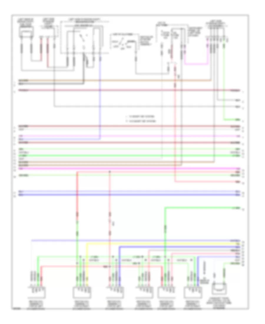
3.5L, Engine Performance Wiring Diagram (5 of 6) for Toyota Sienna XLE 2012
List of elements for 3.5L, Engine Performance Wiring Diagram (5 of 6) for Toyota Sienna XLE 2012:
- (air intake assembly) intake mass air flow meter sub assembly
- (downstream of catalytic converter) oxygen sensor (bank 2 sensor 2)
- (intake manifold assembly)
- (left front of engine compt) vsv (acm)
- (rear of engine) purge vsv
- (rear of engine) vsv (air intake control)
- (right rear of engine compt)
- A1a+
- A1a-
- A2a+
- A2a-
- Air fuel ratio sensor (bank 1 sensor 1) (base of right exhaust manifold)
- Air fuel ratio sensor (bank 2 sensor 1) (base of left exhaust manifold)
- B1 (rear of engine)
- Ba1
- Ba2
- Bank)
- Da6
- E2g
- Fuel injector assembly 1 (top of right cylinder
- Fuel injector assembly 2 (top of left cylinder
- Fuel injector assembly 3 (top of right cylinder
- Fuel injector assembly 4 (top of left cylinder
- Fuel injector assembly 5 (top of right cylinder
- Fuel injector assembly 6 (top of left cylinder
- Ha1a
- Ha2a
- Ht2b
- Ka2
- Nca
- Ox2b
- Pnk
- Red
- Tha
- Throttle w/ motor body assembly
- Vsv (acis)
3.5L, Engine Performance Wiring Diagram (6 of 6) for Toyota Sienna XLE 2012
List of elements for 3.5L, Engine Performance Wiring Diagram (6 of 6) for Toyota Sienna XLE 2012:
- (left rear of vehicle chassis) canister pump module
- (left side of engine compt) j/c a46 & b44
- (rear of engine) e.f.i engine coolant temperature sensor
- (top front of engine)
- (top front of engine) camshaft timing oil control valve (bank 1 exhaust side)
- (top front of engine) camshaft timing oil control valve (bank 1 intake side)
- A1a+
- A1a-
- A2a+
- A2a-
- A46
- Acis
- Acm
- Ad4
- Aicv
- B1 (rear of engine)
- B2 (rear of engine)
- B44
- Ba1
- Ba2
- Bf1
- Canister pressure sensor
- Crankshaft position sensor (front of crankshaft assembly)
- E2g
- Ecm (left rear of engine compt)
- Ekn2
- Eknk
- Eta
- Etha
- Ethw
- Ev1+
- Ev2+
- Ex+
- Ex-
- Ex1b
- Ex2b
- Ht1b
- Igf1
- Ka2
- Knk1
- Knk2
- Knock control sensor (bank 1) (top of engine)
- Knock control sensor (bank 2) (top of engine)
- Leak detection pump
- Meo1
- Nca
- Ne+
- Ne-
- Nsw
- Oc1+
- Oc1-
- Oe1+
- Oe1-
- Ox1b
- Ox2b
- Oxygen sensor (bank 1 sensor 2)
- Pnk
- Ppmp
- Prg
- Red
- Starting/ charging system
- Tha
- Thw
- Valve vent
- Vc2
- Vcta
- Vcv1
- Vcv2
- Vta1
- Vta2
- Vv1+
- Vv1-
- Vv2+
- Vv2-
- Vvl+
- Vvl-
- Vvr+
- Vvr-
- Vvt sensor (bank 1 exhaust side) (top left side of engine)
- Vvt sensor (bank 1 intake side)
- Vvt sensor (bank 2 exhaust side) (top right side of engine)
- Vvt sensor (bank 2 intake side) (top front of engine)
- Gk2