ENGINE PERFORMANCE
3.4L
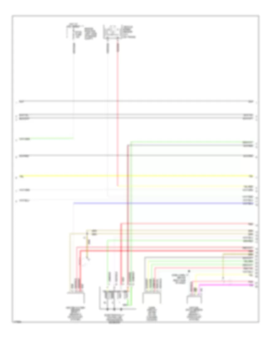
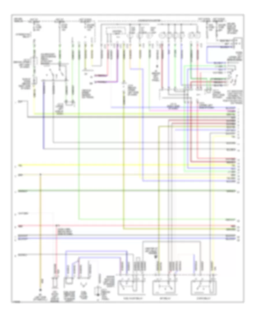
3.4L, Engine Performance Wiring Diagram (1 of 4) for Toyota Tundra Limited 2003

List of elements for 3.4L, Engine Performance Wiring Diagram (1 of 4) for Toyota Tundra Limited 2003:
- (upper left side of dash) diode
- +bm
- 4wd
- A/c system
- A/t indicator light switch
- A/t oil temp
- Ac1
- Acc fuse 15a
- Act
- Batt
- C11
- C12
- C13
- C14
- Ccs
- Combination meter
- Control unit
- Cruise control system
- Data link connector 3 (left side of dash)
- Driver side j/b
- Driver side j/b (behind left side of dash)
- Engine control module (behind right side of dash)
- F/ps
- F11
- G11
- Gauge fuse 10a
- Hot in run or acc
- Hot in run or start
- Hot in start
- Ie (behind left kick panel)
- Ig+
- Ign fuse 5a
- Igsw
- J/c 12 (right side of dash)
- J/c 5 (behind upper left side of dash)
- J/c 5 (w/ cruise control) (behind upper b left side of dash)
- J/c 8 (upper left side of dash)
- J/c 9 (behind upper left side of dash)
- Malf ind lamp
- Mrel
- Nsw
- O/d main switch (center of dash)
- O/d off ind
- Odlp
- Odms
- Oilw
- Pnk
- Red
- Sil
- Sp1
- St-
- Sta
- Sta fuse 5a
- Starting/charging system
- Stp
- Tfn
- Transmission system (4wd circuit)
- Vehicle speed sensor (on trans)
- Wfse
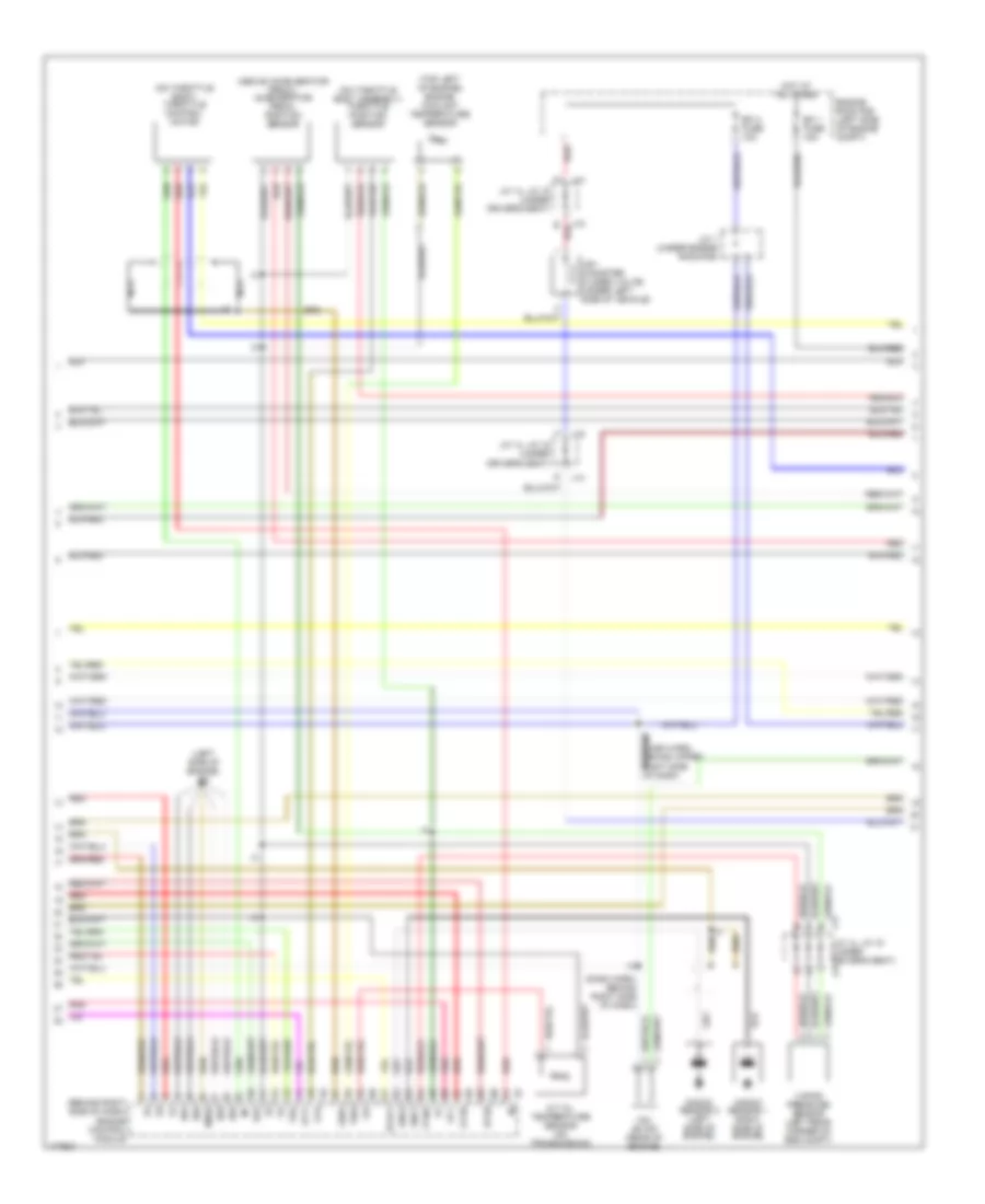
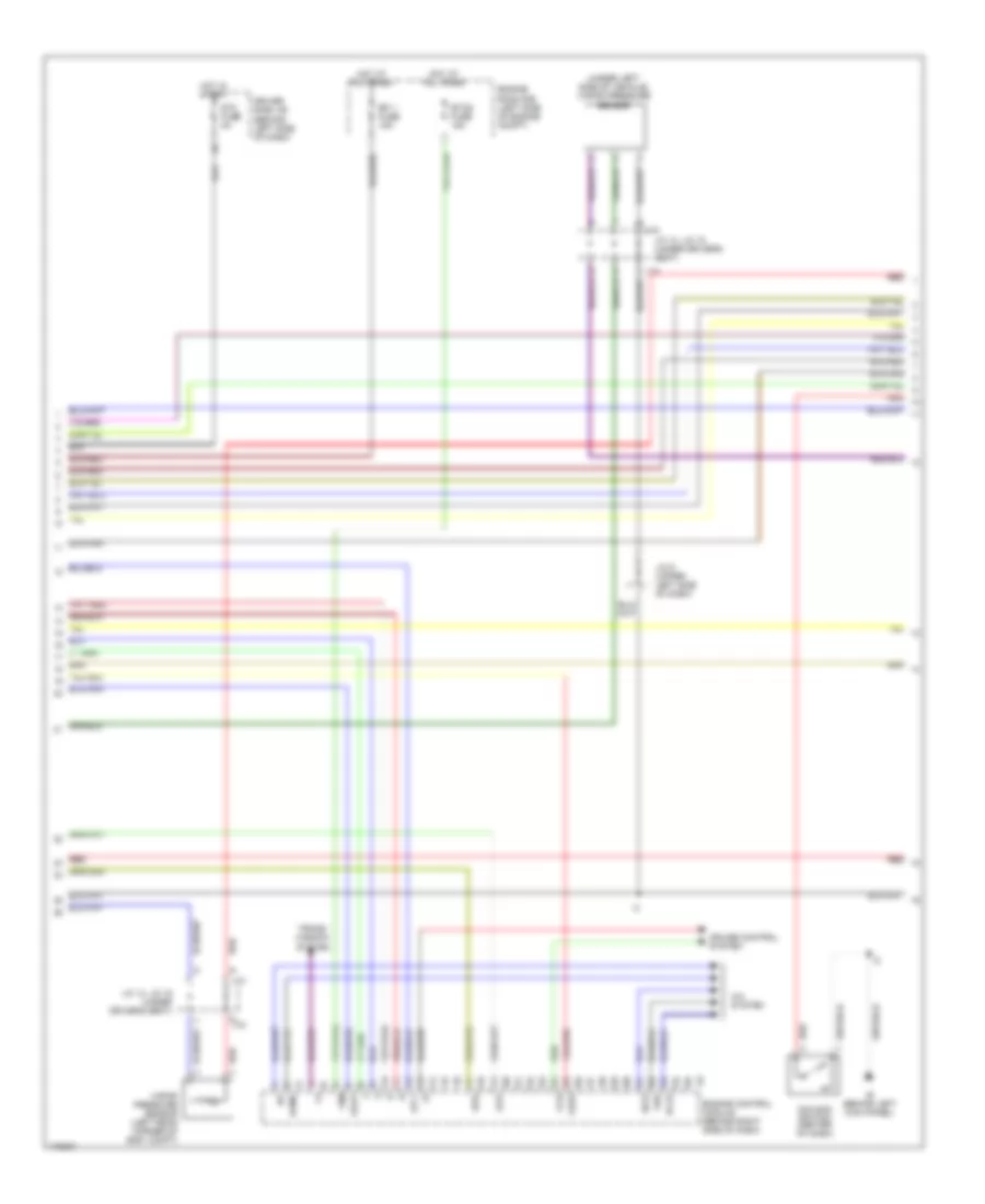
3.4L, Engine Performance Wiring Diagram (2 of 4) for Toyota Tundra Limited 2003
List of elements for 3.4L, Engine Performance Wiring Diagram (2 of 4) for Toyota Tundra Limited 2003:
- Air fuel ratio sensor (bank 1, sensor 1) (on exhaust system)
- Electronically controlled transmission solenoid
- Engine room r/b (left side of engine compt)
- Etcs fuse 15a
- Heated oxygen sensor (bank 1, sensor 2) (on exhaust system)
- Hot at all times
- I3 (dash harn, behind right side of dash)
- Mass airflow meter (on air cleaner housing)
- Pnk
- Red
- Vehicle speed sensor (a/t) (on trans)
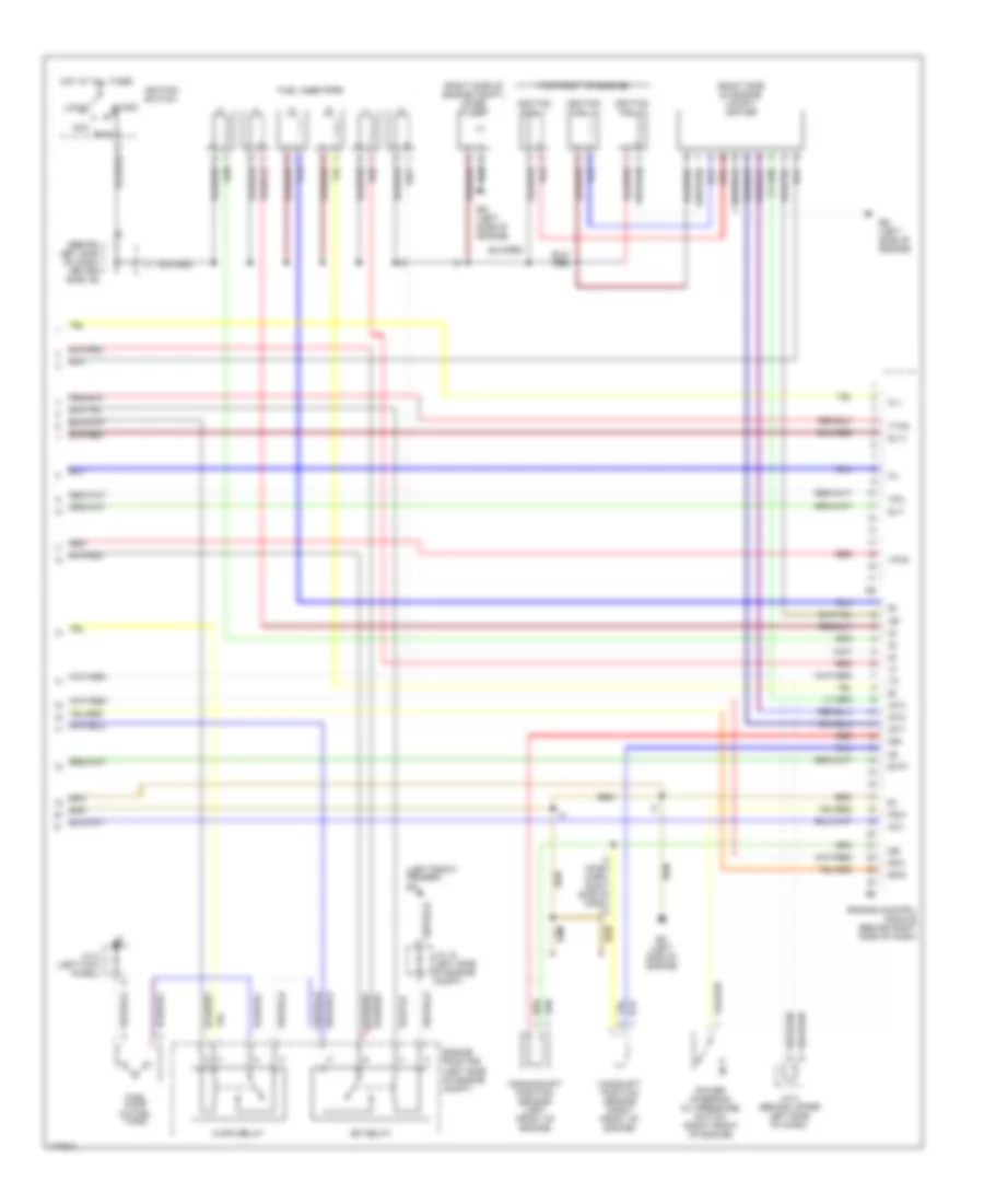
3.4L, Engine Performance Wiring Diagram (3 of 4) for Toyota Tundra Limited 2003
List of elements for 3.4L, Engine Performance Wiring Diagram (3 of 4) for Toyota Tundra Limited 2003:
- (above accelerator pedal) accelerator pedal position sensor
- (behind right side of dash) engine control module
- (dash harn, behind right side of dash)
- (left side of engine) ed
- (on throttle body assembly) throttle position sensor
- (on throttle body) throttle control motor
- (top left of engine) engine coolant temperature sensor
- A/t oil temperature sensor (on transmission)
- Af1+
- Af1-
- E red
- E01
- E02
- E03
- E04
- E2g
- Efi 1 fuse 15a
- Efi 2 fuse 10a
- Engine room r/b (left side of engine compt)
- Ge01
- Hot at all times
- Ht2b
- Htaf1
- J/c 1 (under engine room r/b)
- J/c 14, j/c 15 (under driver's seat)
- J14
- J15
- Knk1
- Knk2
- Knock sensor 1 (right side of engine)
- Knock sensor 2 (left side of engine)
- Me02
- Nca
- Oil
- Ox2b
- Pnk
- Ptnk
- Red
- Tha
- Thw
- Vapor pressure sensor (left rear corner of eng compt)
- Vsv (canister closed valve) (under left side of vehicle)
- Vsv (evap) (rear of engine)
- Vta
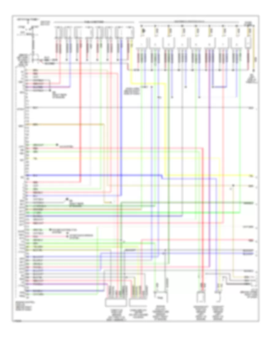
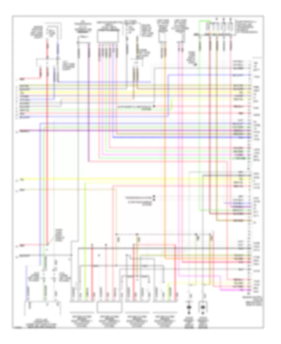
3.4L, Engine Performance Wiring Diagram (4 of 4) for Toyota Tundra Limited 2003
List of elements for 3.4L, Engine Performance Wiring Diagram (4 of 4) for Toyota Tundra Limited 2003:
- (behind left side of dash) driver side j/b
- (left front fender) ea
- (right side of engine compt) igniter
- (right side of engine compt) noise filter
- (top right of engine)
- Acc
- C/opn relay
- Camshaft position sensor (right front of engine)
- Ccv
- Cl+
- Cl-
- Crankshaft position sensor (left front of engine)
- Ed (left side of engine)
- Efi relay
- Engine control module (behind right side of dash)
- Engine room r/b (left side of engine compt)
- Evp1
- Fuel injectors
- Fuel pump (in fuel tank)
- Hot at all times
- I3 (dash harn, right side of dash) jc
- Igf
- Ignition coil 1
- Ignition coil 2
- Ignition coil 3
- Ignition switch
- Igt1
- Igt2
- Igt3
- J/c 18 (left side of engine compt)
- J/c 3 (left kick panel)
- J/c 8 (behind upper left side of dash)
- Lock
- Ne+
- Ne-
- Power steering oil pressure switch (right front of engine)
- Psw
- Red
- Run
- Slt+
- Slt-
- Sp2+
- Sp2-
- Start
- Vpa
- Vpa2
- Vta2
4.7L
4.7L, Engine Performance Wiring Diagram (1 of 4) for Toyota Tundra Limited 2003
List of elements for 4.7L, Engine Performance Wiring Diagram (1 of 4) for Toyota Tundra Limited 2003:
- (behind left side of dash) driver side j/b
- (dash harn, behind right side of dash)
- A/c system
- Acc
- Accr
- Camshaft position sensor (left front of engine)
- Ccv
- Crankshaft position sensor (left front of engine)
- E01
- E02
- E03
- E2g
- Eb (right rear of engine)
- Ec (left side of firewall)
- Engine control module (behind right side of dash)
- Engine coolant temperature sensor (right front of engine)
- Fpr
- Fuel injectors
- G2+
- G2-
- Ge01
- Hot at all times
- Igf1
- Igf2
- Igniters & ignition coils
- Ignition switch
- Igt1
- Igt2
- Igt3
- Igt4
- Igt5
- Igt6
- Igt7
- Igt8
- J/c 19 (behind upper right side of dash)
- Lck1
- Lock
- Mass airflow meter (on air cleaner housing)
- Me01
- Nca
- Ne+
- Ne-
- Noise filter
- Nsw
- Pnk
- Power distribution system
- Prg
- Red
- Run
- Sta
- Start
- Starting/charging system
- Stsw
- Tha
- Throttle position sensor (on throttle body assembly)
- Thw
- Vta1
- Vta2
4.7L, Engine Performance Wiring Diagram (2 of 4) for Toyota Tundra Limited 2003
List of elements for 4.7L, Engine Performance Wiring Diagram (2 of 4) for Toyota Tundra Limited 2003:
- (center of left front fender) ea
- (dash harn, behind right side of dash)
- (on bracket, above brake pedal) stoplight switch
- A/t indicator light switch (integral to park/neutral position switch) (on trans)
- A/t oil temp
- Acc fuse 15a
- C j/c 10 (upper left side of dash)
- C/opn relay
- C11
- C12
- C13
- C14
- Combination meter
- Control unit
- Diode (a/t) (upper left side of dash)
- Driver side j/b
- Driver side j/b (behind left side of dash)
- Ec (left side of firewall)
- Efi relay
- Engine room r/b (left side of engine compt)
- Fuel pump (in fuel tank)
- Fuel pump relay
- Fuel pump resistor (left side of engine compt)
- G11
- Gauge fuse 10a
- Hot at all times
- Hot in run or acc
- Hot in run or start
- Idle-up diode (behind right side of dash)
- Ie (behind left kick panel)
- Ig+
- Integration relay
- J/c 10 (behind upper left side of dash)
- J/c 11 (upper right side of dash)
- J/c 12 (right side of dash)
- J/c 3 (behind left kick panel)
- J/c 8 (upper left side of dash)
- J/c 9 (behind upper left side of dash)
- Malf ind lamp
- O/d off ind
- Red
- Stop fuse 15a
- Tail fuse 15a
- Vehicle speed sensor (on trans)
- Vsv (evap) (left side of engine)
4.7L, Engine Performance Wiring Diagram (3 of 4) for Toyota Tundra Limited 2003
List of elements for 4.7L, Engine Performance Wiring Diagram (3 of 4) for Toyota Tundra Limited 2003:
- (under left side of vehicle) vapor pressure sensor
- +bm
- A/c system
- A/cs
- Acld
- Acmg
- Ccs
- Cruise control system
- Driver side j/b (behind left side of dash)
- Efi 1 fuse 15a
- Engine control module (behind right side of dash)
- Engine room r/b (left side of engine compt)
- Etcs fuse 15a
- Hot at all times
- Hot in start
- Ie (behind left kick panel)
- J/c 14, j/c 15 (under driver's seat)
- J/c 9 (upper left side of dash)
- J14
- J14 h
- J15
- O/d main switch (center of dash)
- Odlp
- Oilw
- Red
- Spd
- St1-
- Sta fuse 5a
- Stp
- The
- Trans- mission system
- Vapor pressure sensor (left rear corner of eng compt)
4.7L, Engine Performance Wiring Diagram (4 of 4) for Toyota Tundra Limited 2003
List of elements for 4.7L, Engine Performance Wiring Diagram (4 of 4) for Toyota Tundra Limited 2003:
- (above accelerator pedal) accel pedal position sensor
- (dash harn right side of dash)
- (dash harn right side of dash) i5
- (left side of trans) o/d direct clutch speed sensor
- (left side of trans) vehicle speed sensor
- (on transmission)
- (upper left side of dash) j/c 5
- +b2
- 4wd
- A/t oil temperature sensor
- Batt
- D red
- Data link connector 3 (under left side of dash, near center console)
- Driver side j/b (behind left side of dash)
- Efi 2 fuse 15a
- Electronically controlled transmission solenoid (in transmission)
- Els
- Engine control module (behind right side of dash)
- Engine room r/b (left side of engine compt)
- Epa
- Epa2
- F/ps
- F11
- Heated oxygen sensor (bank 1 sensor 1) (on exhaust system)
- Heated oxygen sensor (bank 1 sensor 2) (on exhaust system)
- Heated oxygen sensor (bank 2 sensor 1) (on exhaust system)
- Heated oxygen sensor (bank 2 sensor 2) (on exhaust system)
- Hot in run or start
- Ht1a
- Ht1b
- Ht2a
- Ht2b
- Ign fuse 5a
- Igsw
- J/c 1 (left side of engine compt)
- J/c 5 (upper left side of dash)
- J/c 8 (upper left side of dash)
- Knk1
- Knk2
- Knock sensor 1 (left side of engine)
- Knock sensor 2 (right side of engine)
- Mrel
- Nca
- Nco+
- Nco-
- Odms
- Ox1a
- Ox1b
- Ox2a
- Ox2b
- Pnk
- Ptnk
- Red
- Sil
- Slt
- Slt+
- Slt-
- Sp2+
- Sp2-
- Star
- Starting/charging system
- Tach
- Thoc
- Transmission system
- Vcp2
- Vcpa
- Vpa
- Vpa2
- Wfse