ENGINE PERFORMANCE
3.4L
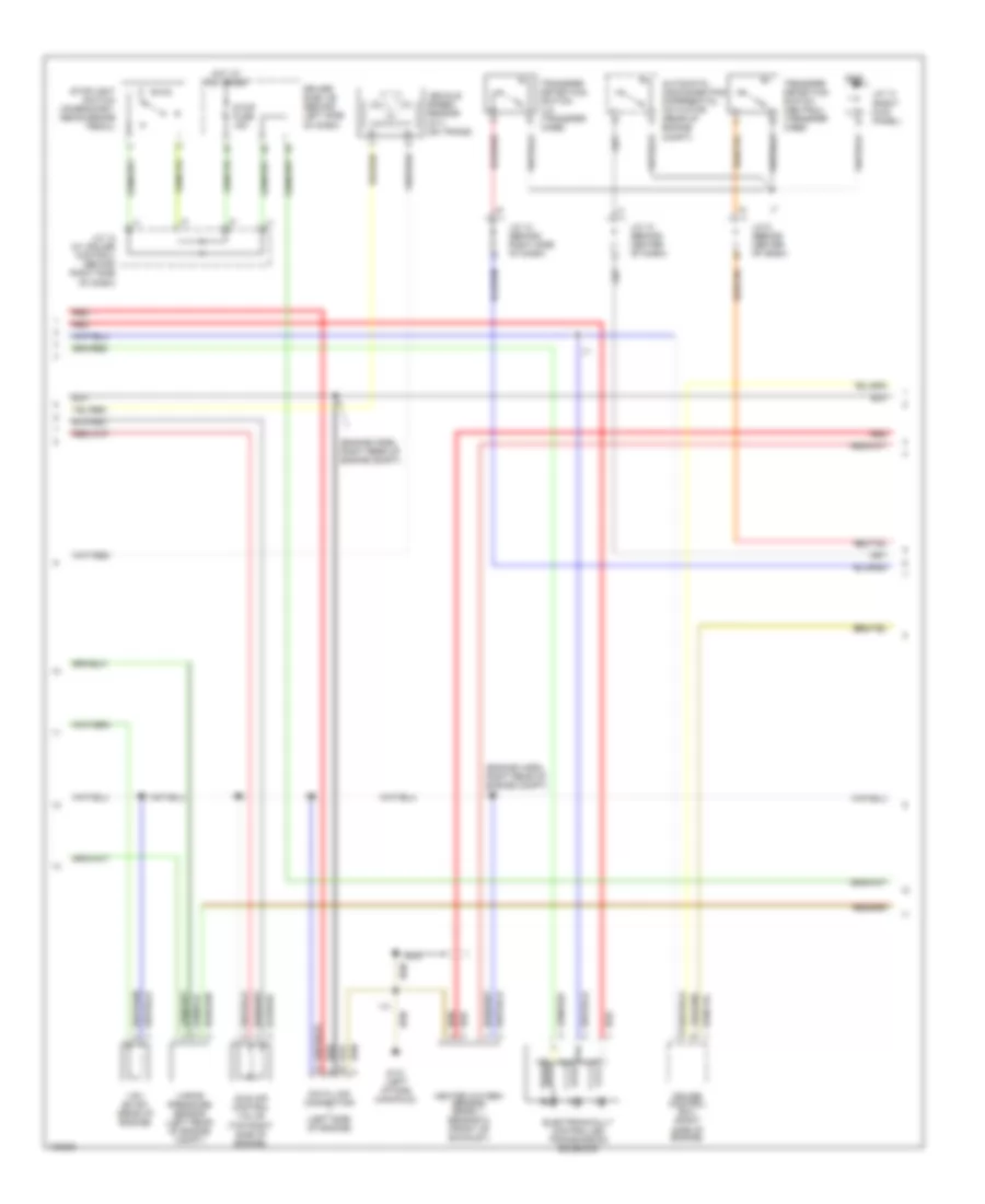
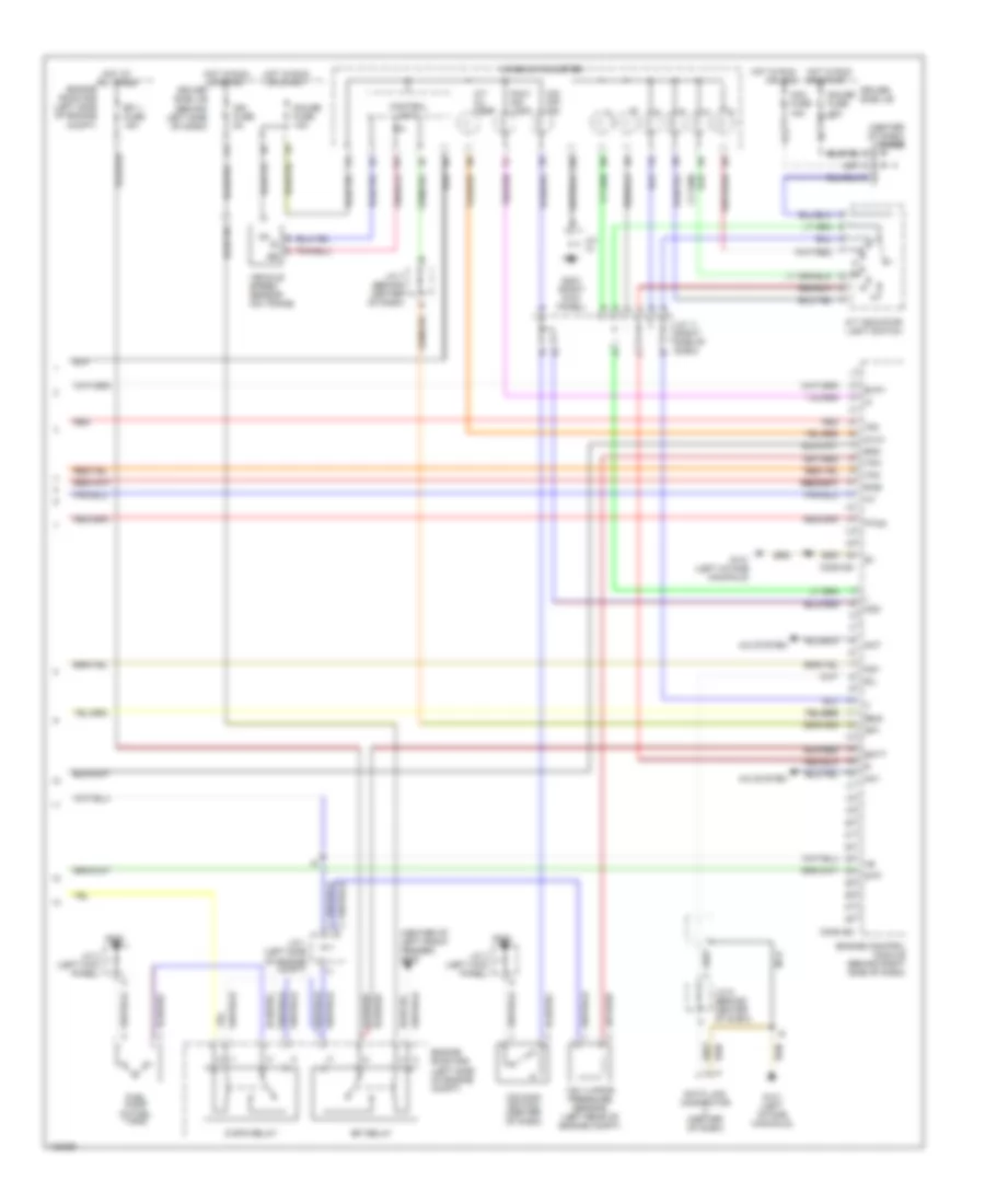
3.4L, Engine Performance Wiring Diagrams, California (1 of 3) for Toyota Tundra SR5 2000

List of elements for 3.4L, Engine Performance Wiring Diagrams, California (1 of 3) for Toyota Tundra SR5 2000:
- (behind left side of dash) driver side j/b
- (engine harn, right rear of engine compt)
- (right side of engine compt) igniter
- (right side of engine compt) noise filter
- (top right of engine)
- A/t oil temperature sensor (top of transmission)
- Acc
- Af1+
- Af1-
- Air fuel ratio sensor (bank 1, sensor 1) (on front of exhaust)
- Camshaft position sensor (right front of engine)
- Conn e5
- Conn e6
- Crankshaft position sensor (left front of engine)
- E01
- E02
- E03
- E05
- E2g
- Engine control module (behind right side of dash)
- Engine coolant temperature sensor (top front of engine)
- Evp1
- Fuel injectors
- G131 (left intake manifold)
- Hot at all times
- Htaf1
- I11
- I12
- I13
- I14
- I15
- Igf
- Ignition coil 1
- Ignition coil 2
- Ignition coil 3
- Ignition switch
- Igt1
- Igt2
- Igt3
- Knk1
- Knk2
- Knock sensor 1 (right side of engine block)
- Knock sensor 2 (left side of engine block)
- Lock
- Mass airflow meter (on air intake)
- Nca
- Ne+
- Ne-
- Oil
- Pnk
- Power steering oil pressure switch (front of engine)
- Psw
- Red
- Rsc
- Rsd
- Run
- Sp2+
- Spd-
- Start
- Te1
- Tha
- Throttle position sensor (on throttle body)
- Thw
- Vta
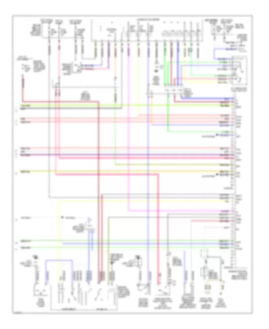
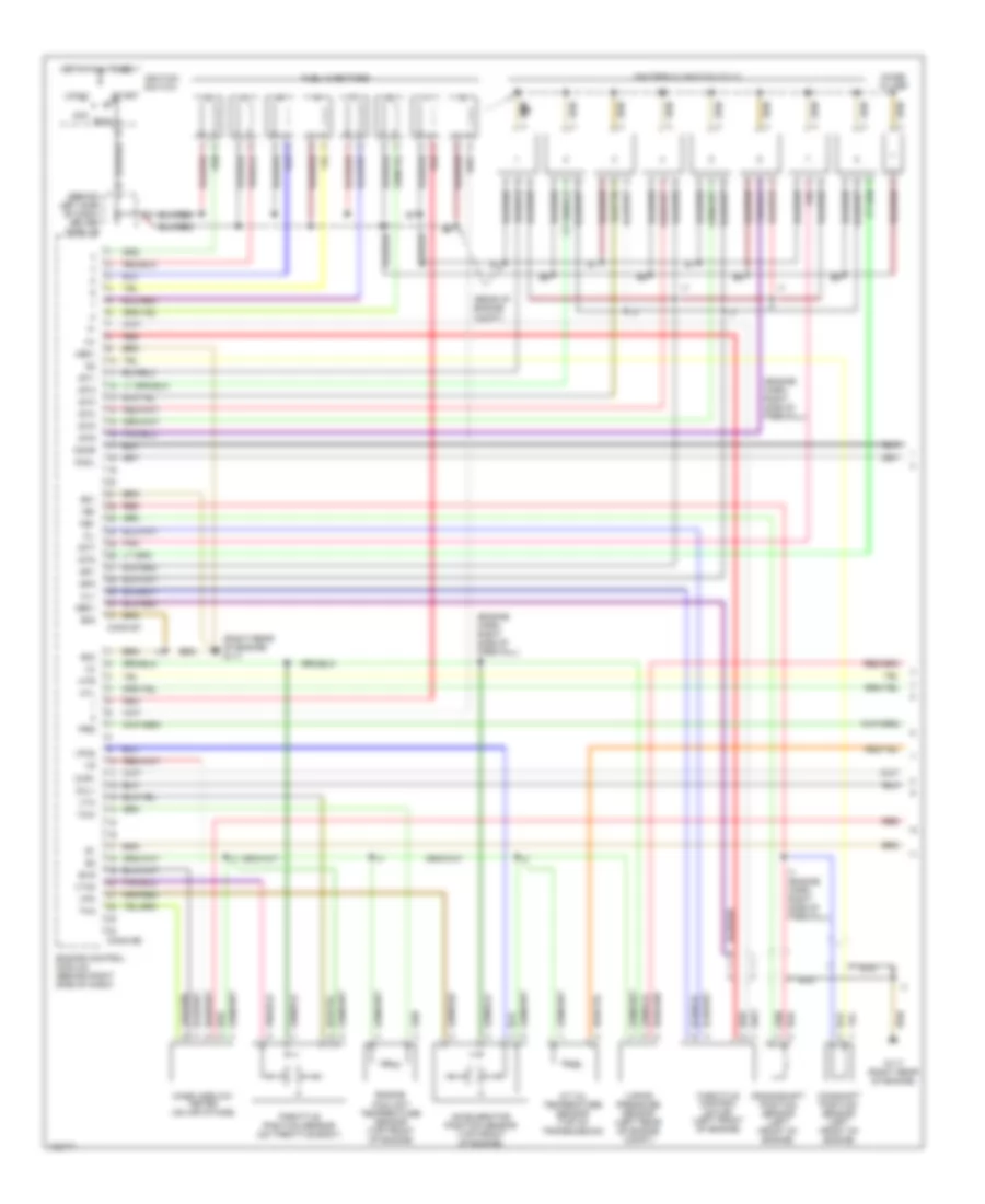
3.4L, Engine Performance Wiring Diagrams, California (2 of 3) for Toyota Tundra SR5 2000
List of elements for 3.4L, Engine Performance Wiring Diagrams, California (2 of 3) for Toyota Tundra SR5 2000:
- (engine harn, right rear of engine compt)
- (engine harn, right rear of engine compt) i12
- Automatic disconnecting differential actuator (rear of engine compt)
- Cruise control ecu (right side of engine)
- Data link connector (left side of engine)
- Driver side j/b (behind left side of dash)
- Electronically controlled transmission solenoid
- G131 (left intake manifold)
- G203
- Heated oxygen sensor (bank 1, sensor 2) (front of exhaust)
- Hot at all times
- I12
- I14
- Idle air control valve (top right side of engine)
- J/c 10 (behind center of dash)
- J/c 12 (behind right side of dash)
- J/c 12 (w/ cruise control) (behind right side of dash)
- J/c 13 (right kick panel)
- J/c 9 (behind center of dash)
- Nca
- Red
- Stop fuse 15a
- Stoplight switch (on bracket, above brake pedal)
- Transfer detection switch (l4) (transfer case)
- Transfer detection switch (neutral) (transfer case)
- Vapor pressure sensor (left rear of engine compt)
- Vehicle speed sensor (a/t) (on trans)
- Vsv (evap) (rear of engine)
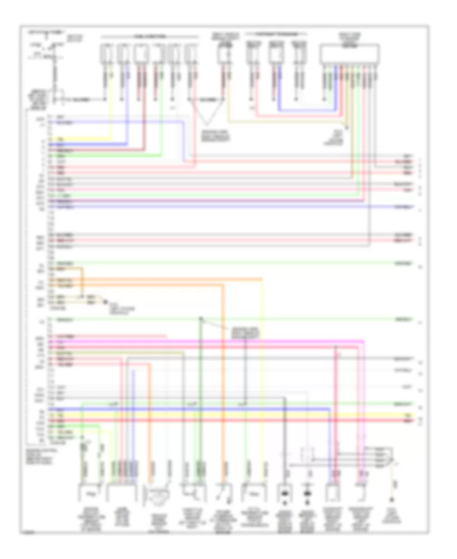
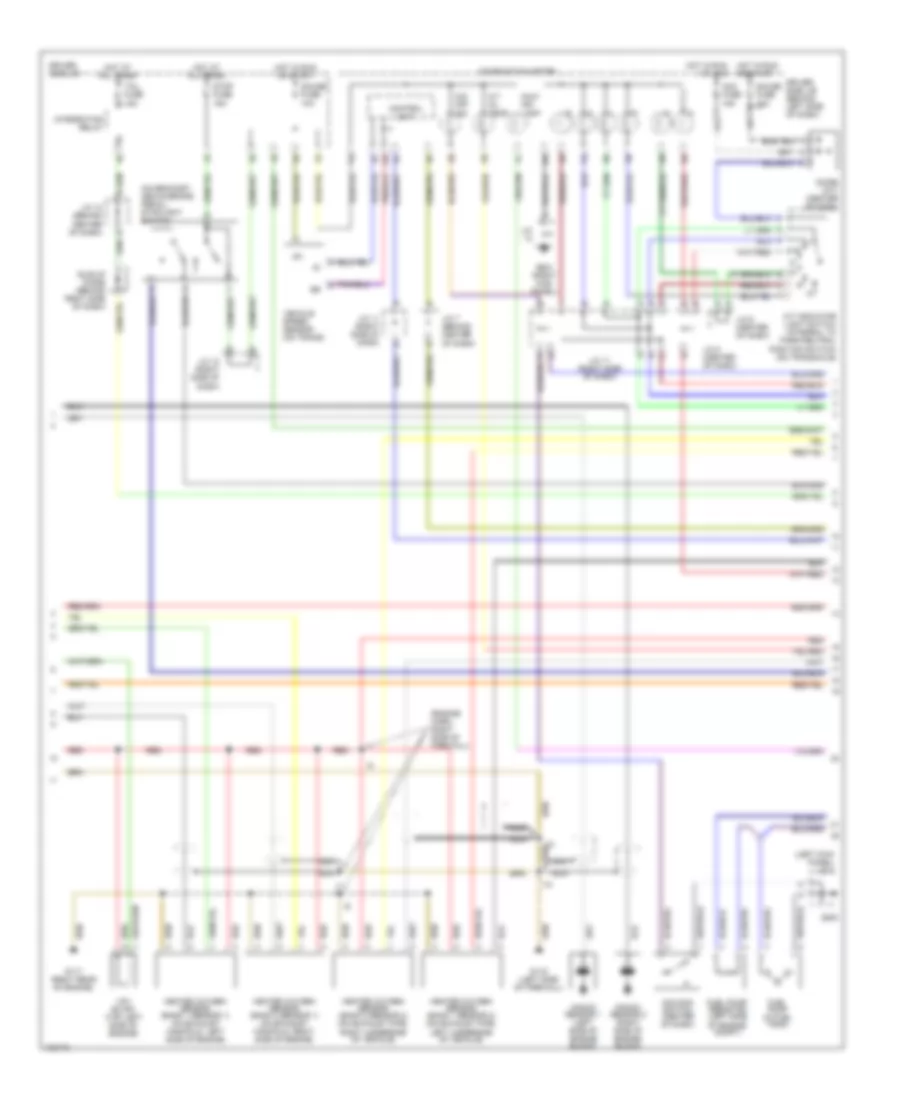
3.4L, Engine Performance Wiring Diagrams, California (3 of 3) for Toyota Tundra SR5 2000
List of elements for 3.4L, Engine Performance Wiring Diagrams, California (3 of 3) for Toyota Tundra SR5 2000:
- (center of dash) diode
- (center of left front fender) g100
- 11f
- 11g
- 13a
- 15b
- 4wd
- A pnk
- A/c system
- A/t
- A/t indicator light switch
- A/t oil temp
- Ac1
- Acc fuse 15a
- Act
- Batt
- C/opn relay
- Combination meter
- Conn e3
- Conn e4
- Control unit
- Data link connector (center of dash)
- Driver side j/b
- Driver side j/b (behind left side of dash)
- Efi 1 fuse 15a
- Efi relay
- Engine control module (behind right side of dash)
- Engine room r/b (left side of engine compt)
- Fuel pump (in fuel tank)
- G131 (left intake manifold)
- G200
- G203 (right kick panel)
- Gauge fuse 10a
- Hot at all times
- Hot in run hot in run hot in run or acc
- Hot in run or start
- Hot in start
- Hts hts
- Idlo idlo
- Ig+
- Ign fuse 5a
- Igsw
- J/c
- J/c 1 (left side of engine compt)
- J/c 11 (right side of dash)
- J/c 3 (left kick panel)
- J/c 5 (behind center of dash)
- J/c 6 (behind center of dash)
- J/c 7 (behind center of dash)
- M/t
- Malf ind lamp
- Mrel
- Nca
- Nsw
- O/d main switch (center of dash)
- O/d off ind
- Od1
- Od2
- Oilw
- Oxs
- Park/neutral position switch (or) clutch start switch
- Pnk
- Ptnk
- Red
- Sil
- Sp1
- Sta
- Sta fuse 5a
- Stp
- Tfn
- Tpc
- Vehicle speed sensor (on trans)
- Vsv (vapor pressure sensor) (left rear of engine compt)
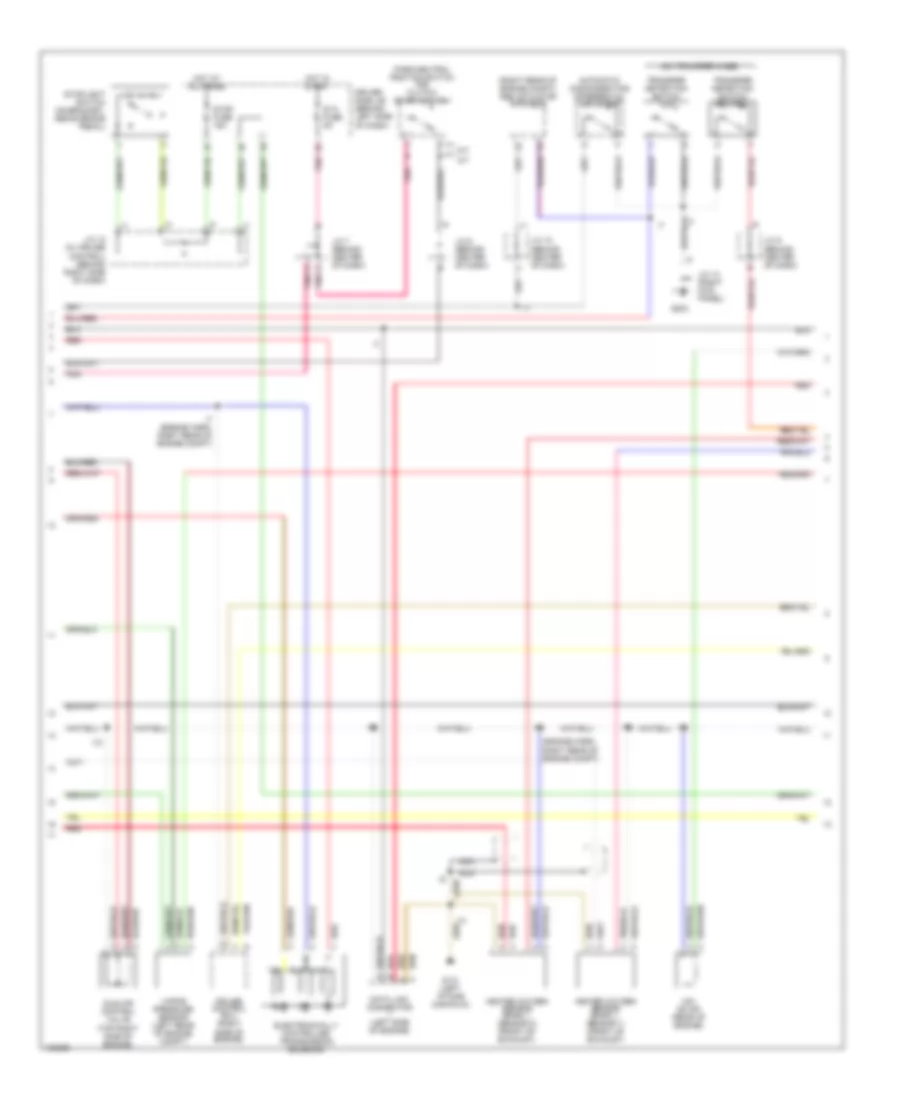
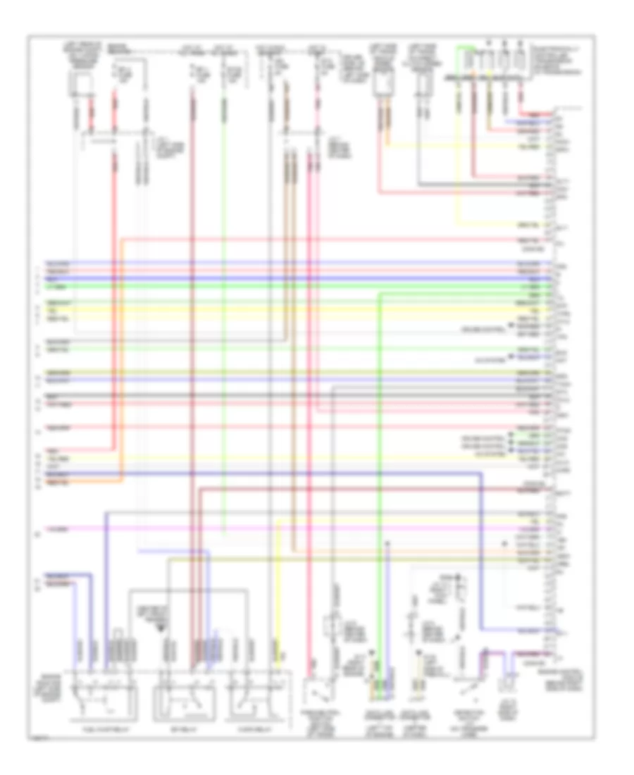
3.4L, Engine Performance Wiring Diagrams, Except California (1 of 3) for Toyota Tundra SR5 2000
List of elements for 3.4L, Engine Performance Wiring Diagrams, Except California (1 of 3) for Toyota Tundra SR5 2000:
- (behind left side of dash) driver side j/b
- (engine harn, right rear of engine compt)
- (right side of engine compt) igniter
- (right side of engine compt) noise filter
- (top right of engine)
- 4wd
- A/t oil temperature sensor (top of transmission)
- Acc
- Camshaft position sensor (right front of engine)
- Conn e5
- Conn e6
- Crankshaft position sensor (left front of engine)
- E01
- E02
- E03
- Engine control module (behind right side of dash)
- Engine coolant temperature sensor (top front of engine)
- Fuel injectors
- G131 (left intake manifold)
- Hot at all times
- I11
- I13
- I15
- Igf
- Ignition coil 1
- Ignition coil 2
- Ignition coil 3
- Ignition switch
- Igt1
- Igt2
- Igt3
- Knk1
- Knk2
- Knock sensor 1 (right side of engine block)
- Knock sensor 2 (left side of engine block)
- Lock
- Mass airflow meter (on air intake)
- Nca
- Ne+
- Ne-
- Nsw
- Oil
- Ox1
- Oxs
- Pnk
- Power steering oil pressure switch (front of engine)
- Psw
- Red
- Rsc
- Rso
- Run
- Sp2+
- Spd-
- Sta
- Start
- Tha
- Throttle position sensor (on throttle body)
- Thw
- Vehicle speed sensor (a/t) (on trans)
- Vta
3.4L, Engine Performance Wiring Diagrams, Except California (2 of 3) for Toyota Tundra SR5 2000
List of elements for 3.4L, Engine Performance Wiring Diagrams, Except California (2 of 3) for Toyota Tundra SR5 2000:
- (engine harn, right rear of engine compt)
- (on transfer case)
- (right rear of engine compt) abs actuator with ecu
- A pnk
- A/t
- Automatic disconnecting differential actuator
- Cruise control ecu (right side of engine)
- Data link connector (left side of engine)
- Driver side j/b (behind left side of dash)
- Electronically controlled transmission solenoid
- G131 (left intake manifold)
- G203
- Heated oxygen sensor (bank 1, sensor 1) (front of exhaust)
- Heated oxygen sensor (bank 1, sensor 2) (front of exhaust)
- Hot at all times
- Hot in start
- I12
- I14
- I7 (engine harn, right rear of engine compt)
- Idle air control valve (top right side of engine)
- J/c 10 (behind center of dash)
- J/c 12 (w/ cruise control) (behind right side of dash)
- J/c 13 (right kick panel)
- J/c 6 (behind center of dash)
- J/c 7 (behind center of dash)
- J/c 9 (behind center of dash)
- M/t
- Nca
- Park/neutral position switch (or) clutch start switch
- Pnk
- Red
- Sta fuse 5a
- Stop fuse 15a
- Stoplight switch (on bracket, above brake pedal)
- Transfer detection switch (l4)
- Transfer detection switch (neutral)
- Vapor pressure sensor (left rear of engine compt)
- Vsv (evap) (rear of engine)
3.4L, Engine Performance Wiring Diagrams, Except California (3 of 3) for Toyota Tundra SR5 2000
List of elements for 3.4L, Engine Performance Wiring Diagrams, Except California (3 of 3) for Toyota Tundra SR5 2000:
- (center of dash) diode
- (center of left front fender) g100
- 11f
- 11g
- 13a
- 15b
- A/c system
- A/t indicator light switch
- A/t oil temp
- Ac1
- Acc fuse 15a
- Act
- Batt
- C/opn relay
- Combination meter
- Conn e3
- Conn e4
- Control unit
- Data link connector (center of dash)
- Driver side j/b
- Driver side j/b (behind left side of dash)
- E2g
- Efi 1 fuse 15a
- Efi relay
- Engine control module (behind right side of dash)
- Engine room r/b (left side of engine compt)
- Evp1
- Fuel pump (in fuel tank)
- G131 (left intake manifold)
- G200
- G203 (right kick panel)
- Gauge fuse 10a
- Hot at all times
- Hot in run or acc
- Hot in run or start
- Hts hts
- I14
- Idlo idlo
- Ig+
- Ign fuse 5a
- J/c
- J/c 1 (left side of engine compt)
- J/c 11 (right side of dash)
- J/c 3 (left kick panel)
- J/c 5 (behind center of dash)
- J/c 7 (behind center of dash)
- Malf ind lamp
- Nca
- O/d main switch (center of dash)
- O/d off ind
- Od1
- Od2
- Oilw
- Ptnk
- Red
- Sil
- Sp1
- Stp
- Te1
- Tfn
- Tpc
- Vehicle speed sensor (on trans)
- Vsv (vapor pressure sensor) (left rear of engine compt)
4.7L
4.7L, Engine Performance Wiring Diagrams (1 of 3) for Toyota Tundra SR5 2000
List of elements for 4.7L, Engine Performance Wiring Diagrams (1 of 3) for Toyota Tundra SR5 2000:
- (behind left side of dash) driver side j/b
- (engine harn, right side of firewall)
- (engine harn, right side of firewall) i7
- (rear of engine compt)
- (right rear of engine) g117
- A/t oil temperature sensor (top of transmission)
- Acc
- Accelerator position sensor (top front of engine)
- Camshaft position sensor (left front of engine)
- Cl+
- Cl-
- Conn e6
- Conn e7
- Crankshaft position sensor (left front of engine)
- E01
- E02
- E03
- Engine control module (behind right side of dash)
- Engine coolant temperature sensor (top front of engine)
- Evg
- Fuel injectors
- G117 (right rear of engine)
- Ge01
- Hot at all times
- Htl
- Htr
- I7 (engine harn, right side of firewall)
- Igf1
- Igf2
- Igniters & ignition coils
- Ignition switch
- Igt1
- Igt2
- Igt3
- Igt4
- Igt5
- Igt6
- Igt7
- Igt8
- Knkl
- Knkr
- Lock
- Mass airflow meter (on air intake)
- Me01
- Nca
- Ne+
- Ne-
- Noise filter
- Oxl1
- Oxr1
- Pnk
- Prg
- Red
- Run
- Start
- Tha
- Throttle control motor (left front of engine)
- Throttle position sensor (on throttle body)
- Thw
- Vapor pressure sensor (left rear of engine compt)
- Vpa
- Vpa2
- Vta
- Vta2
4.7L, Engine Performance Wiring Diagrams (2 of 3) for Toyota Tundra SR5 2000
List of elements for 4.7L, Engine Performance Wiring Diagrams (2 of 3) for Toyota Tundra SR5 2000:
- (engine harn, right side of firewall)
- (left kick panel) j/c 3
- (on bracket, above brake pedal) stoplight switch
- 11g
- 13a
- 15b
- A/t indicator light switch (integral to park/neutral position switch) (on transaxle)
- A/t oil temp
- Acc fuse 15a
- C j/c 12 (right side of dash)
- Combination meter
- Control unit
- Diode (a/t) (center of dash)
- Driver side j/b
- Driver side j/b (behind left side of dash)
- Fuel pump (in fuel tank)
- Fuel pump resistor (left side of engine compt)
- G116 (left side of firewall)
- G117 (right rear of engine)
- G200
- G203 (right kick panel)
- Gauge fuse 10a
- Heated oxygen sensor (bank 1 sensor 1) (on exhaust manifold, left side of engine)
- Heated oxygen sensor (bank 1 sensor 2) (on exhaust pipe, left underside of vehicle)
- Heated oxygen sensor (bank 2 sensor 1) (on exhaust manifold, right side of engine)
- Heated oxygen sensor (bank 2 sensor 2) (on exhaust pipe, right underside of vehicle)
- Hot at all times
- Hot in run or acc
- Hot in run or start
- I10
- Ig+
- Integration relay
- J/c
- J/c 10 (behind center of dash)
- J/c 11 (right side of dash)
- J/c 6 (center of dash)
- J/c 7 (behind center of dash)
- J/c 8 (center of dash)
- Knock sensor 1 (left side of engine block)
- Knock sensor 2 (right side of engine block)
- Malf ind lamp
- Nca
- O/d main switch (center of dash)
- O/d off ind
- Red
- Stop fuse 15a
- Tail fuse 15a
- Vehicle speed sensor (on trans)
- Vsv (evap) (top left side of engine)
4.7L, Engine Performance Wiring Diagrams (3 of 3) for Toyota Tundra SR5 2000
List of elements for 4.7L, Engine Performance Wiring Diagrams (3 of 3) for Toyota Tundra SR5 2000:
- (center of left front fender) g100
- (left rear of engine compt) vsv (vapor pressure sensor
- (left side of trans) o/d direct clutch speed sensor
- (left side of trans) vehicle speed sensor
- +b1
- +bm
- 11f
- A pnk
- A/c
- A/c system
- Act
- Batt
- C/opn relay
- Ccs
- Cms
- Conn e3
- Conn e4
- Conn e5
- Cruise control
- D red
- Data link connector (center of dash)
- Data link connector (left top of engine)
- Detection switch (l4) (on transfer case)
- Driver side j/b (behind left side of dash)
- Efi 1 fuse 15a
- Efi 2 fuse 15a
- Efi relay
- Electronically controlled transmission solenoid (in transmission)
- Els
- Engine control module (behind right side of dash)
- Engine room r/b
- Engine room r/b (left side of engine compt)
- Etcs fuse 15a
- Fpr
- Fuel pump relay
- G116 (left side of firewall)
- G117 (right rear of engine)
- G203
- Hot at all times
- Hot in run or start
- Hot in start
- Htl2
- Htr2
- Ign fuse 5a
- Igsw
- J/c 1 (left side of engine compt)
- J/c 12 (right side of dash)
- J/c 13 (right kick panel)
- J/c 5 (behind center of dash)
- J/c 6 (behind center of dash)
- J/c 7 (behind center of dash)
- Mrel
- Nco+
- Nco-
- Nsw
- Od2
- Oil
- Oilw
- Oxl2
- Oxr2
- Park/neutral position switch (left side of trans)
- Pnk
- Ptnk
- Red
- Sil
- Slt
- Slt+
- Slt-
- Sp2+
- Sp2-
- Spd
- St1-
- Sta
- Sta fuse 5a
- Stp
- Tach
- Tpc