ENGINE PERFORMANCE
2.7L
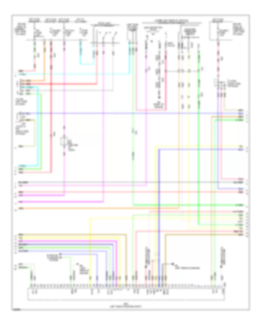
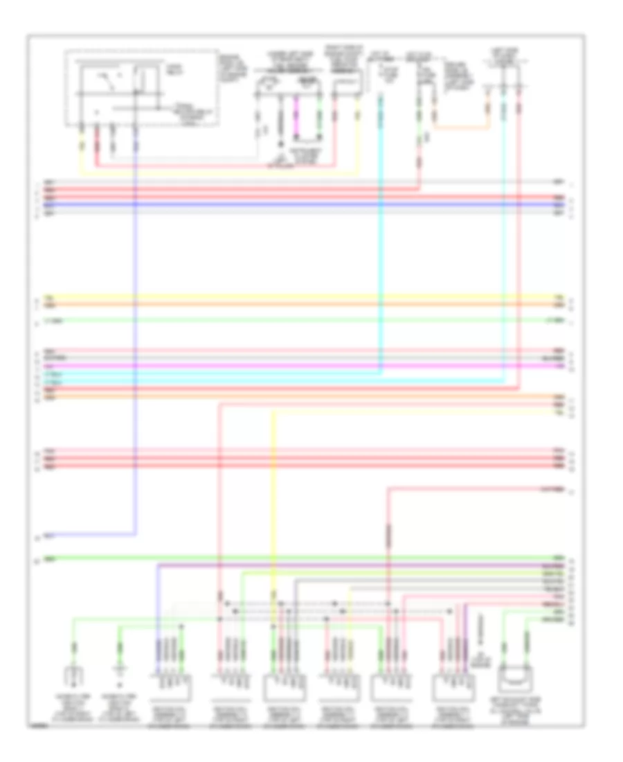
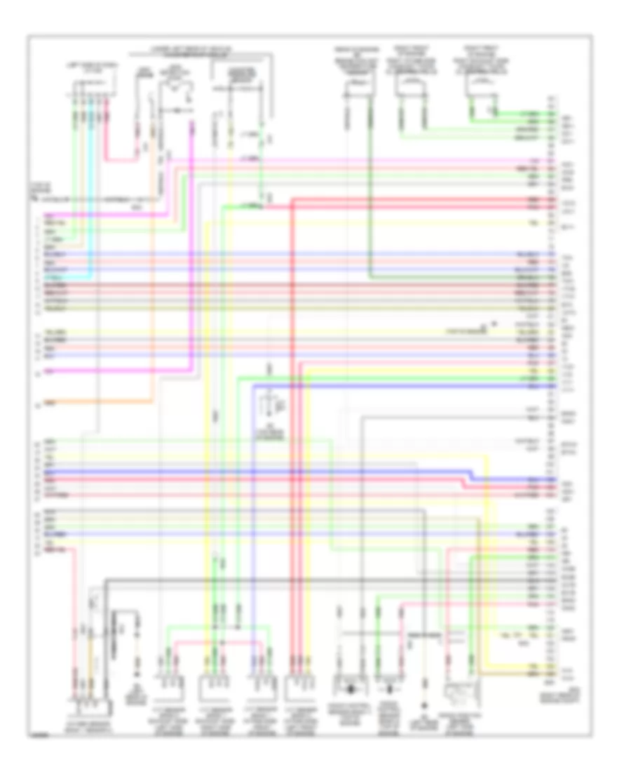
2.7L, Engine Performance Wiring Diagram (1 of 4) for Toyota Venza LE 2013

List of elements for 2.7L, Engine Performance Wiring Diagram (1 of 4) for Toyota Venza LE 2013:
- (left "c" pillar) l3
- (left side of dash) j/c a46
- (under left side of rear seat) fuel sender gauge assembly
- +b2
- +bm
- A43
- A49
- A5 (left side of dash)
- Accelerator position sensor (accelerator pedal assembly) (left side of dash)
- Ae1
- Anti-theft system
- Ba2
- Batt
- C/opn relay
- Camshaft timing oil control valve (bank 1 exhaust side) (top right of engine)
- Camshaft timing oil control valve (bank 1 intake side) (right side of engine)
- Canh
- Canl
- Cann
- Canp
- Ccs
- Computer data lines system
- Cooling fans system
- Cruise control system
- D42
- D55
- Da5
- Ecm (left side of engine compt)
- Ef2
- Efi 1 fuse 10a
- Efi 2 fuse 15a
- Efi 3 fuse 10a
- Efi 4 fuse 20a
- Efi main 2 relay
- Efi main fuse 20a
- Efi main relay
- Engine room j/b (left side of engine compt)
- Engine room r/b (left side of engine compt)
- Epa
- Epa2
- Etcs fuse 10a
- F10
- F12
- Fanh
- Fanl
- Gauge
- Hot at all times
- I1 (driver's door)
- Id2
- Igsw
- Imi
- Imo
- Instrument cluster system
- J/c a43 & d55 (left side of dash)
- J/c a43 (left side of dash)
- J/c d58 (center of dash)
- J/c d62 (center of dash)
- La1
- Mpmp
- Mrel
- Neo
- Park/neutral position switch assembly (top of transmission)
- Pnk
- Power management control ecu (w/ smart key system) (right side of dash)
- Pump
- Red
- Sftd
- Sftu
- Short pin
- Spd
- St1-
- Sta
- Starting/charging system
- Stp
- Tach
- Transmission control ecu assembly (left front of engine compt)
- Transmission control switch
- Transmissions system
- Vcp2
- Vcpa
- Vpa
- Vpa2
- Vpmp
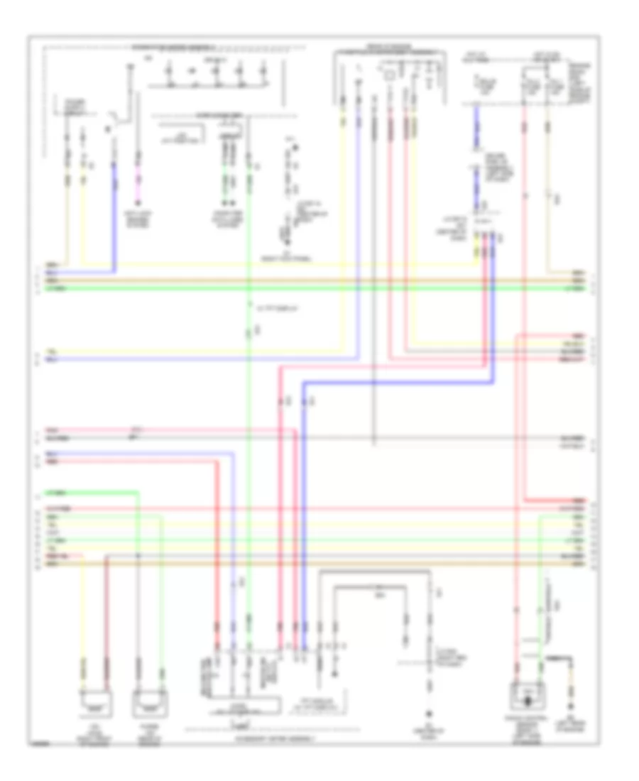
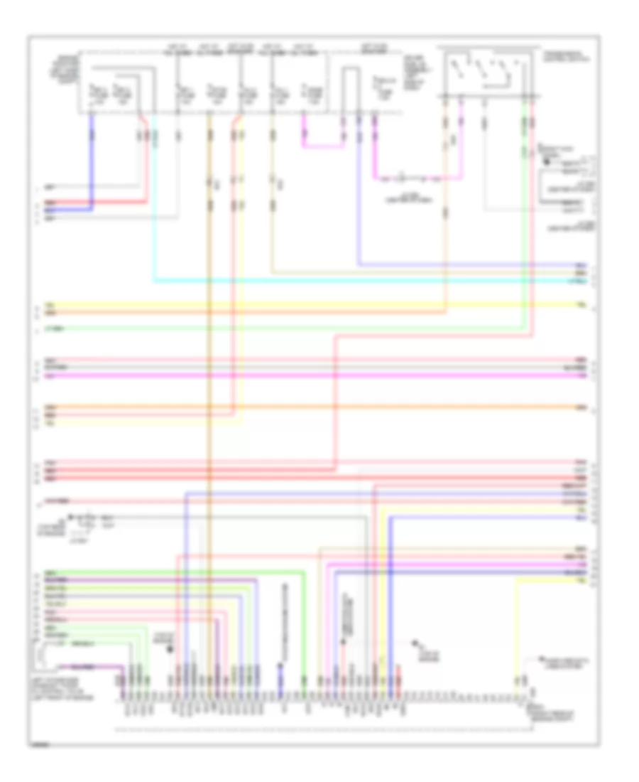
2.7L, Engine Performance Wiring Diagram (2 of 4) for Toyota Venza LE 2013
List of elements for 2.7L, Engine Performance Wiring Diagram (2 of 4) for Toyota Venza LE 2013:
- (left side of dash) j/c a46
- (under left rear of vehicle) canister pump module
- Acis
- Alt
- B4 (front of engine)
- B58
- B6 (left rear of engine)
- Ba1
- Ba2
- C16
- Can+
- Can-
- Canister pressure sensor
- Computer data lines system
- D57
- Da2
- De2
- Driver side j/b assembly (left side of dash)
- E04
- E31
- Ecm (left side of engine compt)
- Ecu-ig 2 fuse 7.5a
- G25
- G38
- Gauge 1 fuse 10a
- Gauge 2 fuse 7.5a
- Ge01
- Ha1a
- Hot at all times
- Hot in on or start
- Ht1b
- Ia1+
- Ia1-
- Igf1
- Ign fuse 10a
- J/c a45 (left side of dash)
- J/c d63 (center of dash)
- J/c e31 & d57 (right side of dash)
- J/c e32 (right end of dash)
- K29
- K36
- La1
- Leak detection pump
- Lines system computer data
- Me01
- Mgnd
- Mtrb
- Nsw
- Oc1+
- Oc1-
- Oe1+
- Oe1-
- Pnk
- Prg
- Red
- Sgnd
- Starting/ charging system
- Stop fuse 10a
- Stop light switch assembly
- Vcc
- Vent valve
- Vgnd
- Vlvb
- Vout
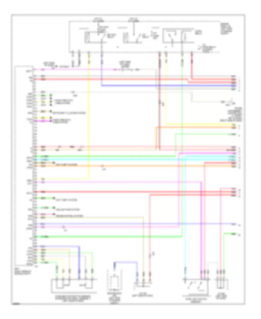
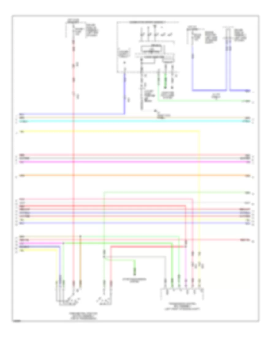
2.7L, Engine Performance Wiring Diagram (3 of 4) for Toyota Venza LE 2013
List of elements for 2.7L, Engine Performance Wiring Diagram (3 of 4) for Toyota Venza LE 2013:
- (center of dash)
- (rear of engine) throttle w/ motor body assembly
- (right end of dash)
- Accessory meter assembly
- Anti-lock brakes system
- B5 (left rear of engine)
- Ba2
- Bu2
- C24
- Can i/f
- Canh
- Canl
- Chk
- Combination meter assembly
- Computer data lines system
- D1 (right kick panel)
- D57
- Display) (w/ tft master ind
- Drive ic
- Driver side j/b assembly (left side of dash)
- E1 (center of dash)
- E31
- Ecu-b fuse 10a
- Ef1
- Ef2
- Engine room r/b (left side of engine compt)
- Hot at all times
- Hot in on or start
- Ig+
- Ig2
- Indicator lamp malfunction
- Inj 1 fuse 15a
- Inj 2 fuse 15a
- J/c d57 & e31
- J/c e31 & d57 (center of dash) d57
- J/c e32
- Knock control sensor (bank 1) (left side of engine)
- Lcd
- Lcd (a/t position)
- Micro (w/ lcd display)
- Micro computer
- Nca
- Pnk
- Purge vsv (rear of engine)
- Red
- Sg7
- Sgnd
- Tft module (w/ tft display)
- Vsv (acis) (right front of engine)
- Vta
- Vta2
- W/ tft display
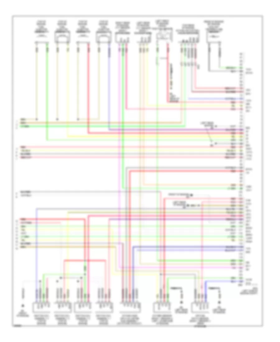
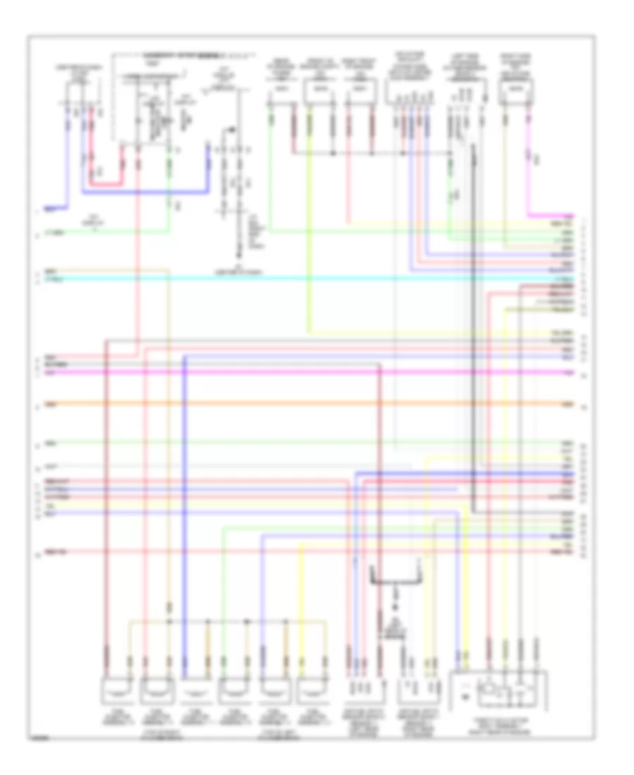
2.7L, Engine Performance Wiring Diagram (4 of 4) for Toyota Venza LE 2013
List of elements for 2.7L, Engine Performance Wiring Diagram (4 of 4) for Toyota Venza LE 2013:
- (front of engine)
- (front of engine) b4
- (left front of engine) crank position sensor
- (left rear engine) b6
- (left rear of engine)
- (left rear of engine) b5
- (left rear of engine) vvt sensor (bank 1 exhaust side)
- (rear of engine) efi engine coolant temperature sensor
- (right rear of engine) vvt sensor (bank 1 intake side)
- (top of engine) fuel injector assembly 1
- (top of engine) fuel injector assembly 2
- (top of engine) fuel injector assembly 3
- (top of engine) fuel injector assembly 4
- (top rear of engine) intake air control valve actuator
- A1a+
- A1a-
- Air fuel ratio sensor (bank 1 sensor 1) (rear of engine)
- B5 (left rear of engine)
- B58
- Bu2
- E01
- E02
- E03
- E2g
- Ecm (left side of engine compt)
- Eia1
- Eknk
- Eppm
- Eta
- Etha
- Ethw
- Ev1+
- Ev1-
- G2+
- G2-
- Gnd
- Ha1a
- Ht1b
- Iac1
- Igf
- Ignition coil assembly 1 (top of engine)
- Ignition coil assembly 2 (top of engine)
- Ignition coil assembly 3 (top of engine)
- Ignition coil assembly 4 (top of engine)
- Igt1
- Igt2
- Igt3
- Igt4
- Intake mass air flow meter sub assembly (on intake air duct)
- Knk1
- Nca
- Ne+
- Ne-
- O1b-
- Out
- Ox1b
- Oxygen sensor (bank 1 sensor 2) (left lower side of engine)
- Pnk
- Ppmp
- Red
- Tha
- Thw
- Vc2
- Vce1
- Vcia
- Vcpp
- Vcta
- Vcv1
- Vdd
- Vta1
- Vta2
- Vve+
- Vve-
- Vvi+
- Vvi-
3.5L
3.5L, Engine Performance Wiring Diagram (1 of 6) for Toyota Venza LE 2013
List of elements for 3.5L, Engine Performance Wiring Diagram (1 of 6) for Toyota Venza LE 2013:
- (left side of dash) a5
- (left side of dash) j/c a43
- +b2
- A/f fuse 20a
- A/f relay
- A41
- Accelerator position sensor (accelerator pedal assembly) (left side of dash)
- Ae1
- Anti-theft system
- Ba1
- Ba2
- Batt
- C/opn relay
- Canh
- Canl
- Cann
- Canp
- Ccs
- Computer data lines system
- Cooling fans system
- Cruise control system
- D42
- Da5
- Ecm (right rear of engine compt)
- Ef2
- Efi main fuse 25a
- Efi main relay
- Engine room j/b (left side of engine compt)
- Engine room r/b (left side of engine compt)
- Epa
- Epa2
- F12
- F18
- Fpr
- Hot at all times
- Igsw
- Imi
- Imo
- Instrument cluster system
- J/c a45 (left side of dash)
- La1
- Mpmp
- Mrel
- Neo
- Pnk
- Power management control ecu (w/ smart key system) (right side of dash)
- Red
- Rfc
- Sftd
- Sftu
- Spd
- St relay
- St1-
- Sta
- Stop light switch assembly
- Tach
- To f/pmp relay (diagram 2 of 6)
- Vcp2
- Vcpa
- Vpa
- Vpa2
- Vpmp
3.5L, Engine Performance Wiring Diagram (2 of 6) for Toyota Venza LE 2013
List of elements for 3.5L, Engine Performance Wiring Diagram (2 of 6) for Toyota Venza LE 2013:
- (left side of dash) j/c a45
- (right side of engine compt) fuel pump resistor assembly
- (under left side of rear seat) fuel sender gauge assembly
- B1 (top of engine)
- C16
- Da2
- Driver side j/b assembly (left side of dash)
- Engine room j/b (left side of engine compt)
- F/pmp relay
- F10
- F11
- F13
- From c/opn relay (diagram 1 of 6)
- Gauge
- Gnd
- Hot at all times
- Hot in on or start
- Igf
- Ign fuse 10a
- Ignition coil assembly 1 (top of right cylinder bank)
- Ignition coil assembly 2 (top of left cylinder bank)
- Ignition coil assembly 3 (top of right cylinder bank)
- Ignition coil assembly 4 (top of left cylinder bank)
- Ignition coil assembly 5 (top of right cylinder bank)
- Ignition coil assembly 6 (top of left cylinder bank)
- Igt1
- Igt2
- Igt3
- Igt4
- Igt5
- Igt6
- Instrument cluster system
- K29
- L3 (left "c" pillar)
- La1
- Left exhaust side camshaft timing oil control valve (left side of engine)
- Noise filter (ignition bank 1) (top of right cylinder bank)
- Noise filter (ignition bank 2) (top of left cylinder bank)
- Pnk
- Pump
- Red
- Stop fuse 10a
3.5L, Engine Performance Wiring Diagram (3 of 6) for Toyota Venza LE 2013
List of elements for 3.5L, Engine Performance Wiring Diagram (3 of 6) for Toyota Venza LE 2013:
- (right kick panel) da5
- (top of engine)
- +bm
- Alt
- B1 (top of engine)
- B3 (top rear of engine)
- B39
- Ba1
- Ba2
- C27
- Can+
- Can-
- Computer data lines system
- Da5
- Dome fuse 7.5a
- Driver side j/b assembly (left side of dash)
- Ecm (right rear of engine compt)
- Ecu-ig fuse 7.5a
- Efi 1 fuse 10a
- Efi 2 fuse 15a
- Efi 3 fuse 10a
- Engine room r/b (left side of engine compt)
- Eo1
- Eo2
- Eo3
- Eo4
- Eo5
- Etcs fuse 10a
- F20
- Ge01
- Ha1a
- Ha2a
- Hot at all times
- Hot in on or start
- Ht1b
- Ht2b
- Igt1
- Igt2
- Igt3
- Igt4
- Igt5
- Igt6
- Inj 1 fuse 15a
- Inj 2 fuse 15a
- J/c b41
- J/c d58 (center of dash)
- J/c d62 (center of dash)
- J/c d63 (center of dash)
- K36
- Left intake side camshaft timing oil control valve (left front of engine)
- Lines system computer data
- Oc2+
- Oc2-
- Oe2+
- Oe2-
- Pnk
- Red
- Starting/charging system
- Stp
- Transmission control switch
3.5L, Engine Performance Wiring Diagram (4 of 6) for Toyota Venza LE 2013
List of elements for 3.5L, Engine Performance Wiring Diagram (4 of 6) for Toyota Venza LE 2013:
- Ba1
- Ba2
- C24
- Can i/f
- Canh
- Canl
- Combination meter assembly
- Computer data lines system
- D1 (right kick panel)
- Da2
- De1
- Drive ic
- Driver side j/b assembly (left end of dash)
- Driver side j/b assembly (left side of dash)
- E31
- Ecu-b fuse 10a
- Engine room r/b (left side of engine compt)
- G38
- Gauge 1 fuse 10a
- Hot at all times
- Hot in on or start
- Ig2
- J/c d57 & e31 (center of d57 dash)
- Lcd (a/t position)
- Micro computer
- Nsw
- Park/neutral position switch assembly (top of transmission)
- Pnk
- Red
- Sta
- Starting/charging system
- Stp
- Transmission control ecu assembly (left front of engine compt)
- W/ tft display
3.5L, Engine Performance Wiring Diagram (5 of 6) for Toyota Venza LE 2013
List of elements for 3.5L, Engine Performance Wiring Diagram (5 of 6) for Toyota Venza LE 2013:
- (center of dash) j/c d57 & e31
- (front of engine compt) vsv (acm)
- (left side of engine) oxygen sensor (bank 2 sensor 2)
- (on intake air duct)
- (rear of engine) purge vsv
- (right front of engine)
- (right rear of engine)
- (right side of engine) vsv (air intake control)
- (top of left cylinder bank)
- (top of right cylinder bank)
- A1a+
- A1a-
- A2a+
- A2a-
- Accessory meter assembly
- Air fuel ratio sensor (bank 1 sensor 1) (right rear of engine)
- Air fuel ratio sensor (bank 2 sensor 1) (left rear of engine)
- B2 (left rear of engine)
- Ba1
- Ba2
- D57
- E1 (center of dash)
- E2g
- E31
- Ef1
- Ef2
- Fuel injector assembly 1
- Fuel injector assembly 2
- Fuel injector assembly 3
- Fuel injector assembly 4
- Fuel injector assembly 5
- Fuel injector assembly 6
- Ha1a
- Ha2a
- Ht2b
- Intake mass air flow meter sub assembly
- J/c e32 (right end of dash)
- Lcd
- Lcd display
- Malfunction indicator lamp
- Master ind
- Micro (lcd display)
- Nca
- Ox2b
- Pnk
- Red
- Tft display
- Tft module (tft display)
- Tha
- Throttle w/ motor body assembly
- Vsv (acis)
3.5L, Engine Performance Wiring Diagram (6 of 6) for Toyota Venza LE 2013
List of elements for 3.5L, Engine Performance Wiring Diagram (6 of 6) for Toyota Venza LE 2013:
- (front of engine)
- (left side of dash) j/c a46
- (rear of engine) efi engine coolant temperature sensor
- (right front of engine)
- (top of engine) b1
- (under left rear of vehicle)
- A1a+
- A1a-
- A2a+
- A2a-
- Acis
- Acm
- Aicv
- B1 (top of engine)
- B2 (left rear of engine)
- B3 (top rear of engine)
- B39
- Ba1
- Ba2
- Bu1
- Canister pressure sensor
- Canister pump module
- Crank position sensor (left side of engine)
- E2g
- Ecm (right rear of engine compt)
- Ekn2
- Eknk
- Eta
- Etha
- Ethw
- Ev1+
- Ev2+
- Ex+
- Ex-
- Ex1b
- Ex2b
- Ht1b
- Igf1
- J/c b41
- Knk1
- Knk2
- Knock control sensor (bank 1) (top of engine)
- Knock control sensor (bank 2) (top of engine)
- La1
- Leak detection pump
- Meo1
- Nca
- Ne+
- Ne-
- Nsw
- Oc1+
- Oc1-
- Oe1+
- Oe1-
- Ox1b
- Ox2b
- Oxygen sensor (bank 1 sensor 2)
- Pnk
- Ppmp
- Prg
- Red
- Right exhaust side camshaft timing oil control valve
- Right intake side camshaft timing oil control valve
- Tha
- Thw
- Vc2
- Vcta
- Vcv1
- Vcv2
- Vent valve
- Vta1
- Vta2
- Vv1+
- Vv1-
- Vv2+
- Vv2-
- Vvl+
- Vvl-
- Vvr+
- Vvr-
- Vvt sensor (bank 1 exhaust side) (right side of engine)
- Vvt sensor (bank 1 intake side)
- Vvt sensor (bank 2 exhaust side) (left side of engine)
- Vvt sensor (bank 2 intake side) (left front of engine)