ENGINE PERFORMANCE
1.8L TURBO
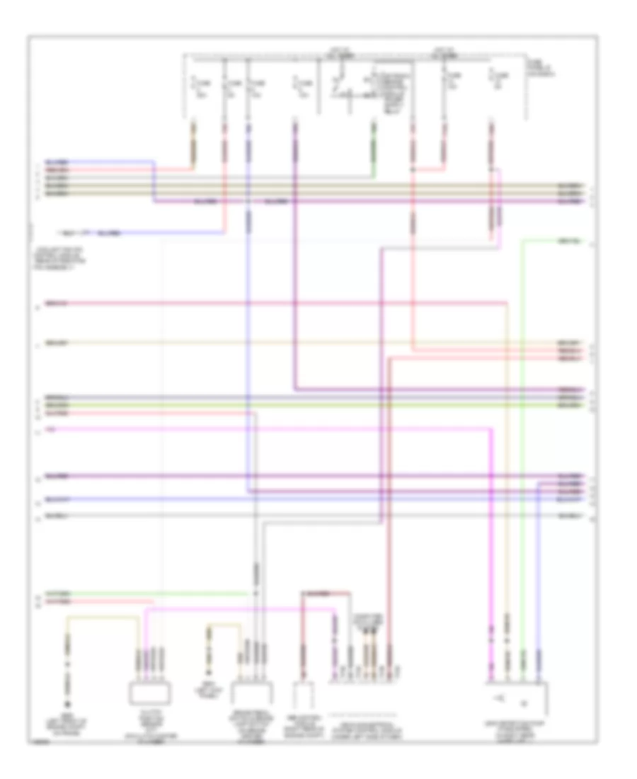
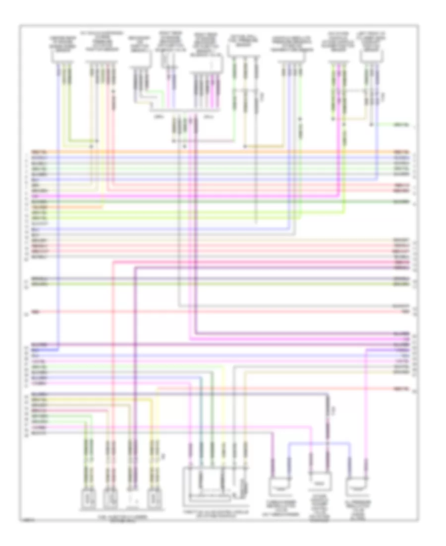
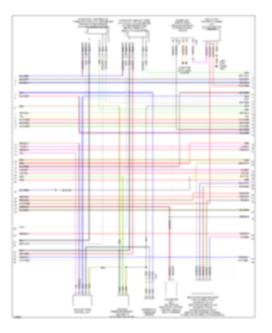
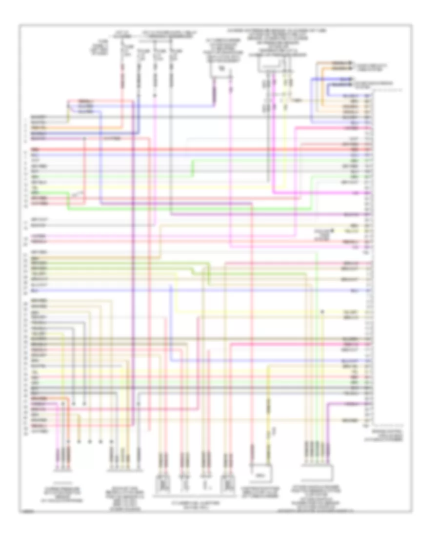
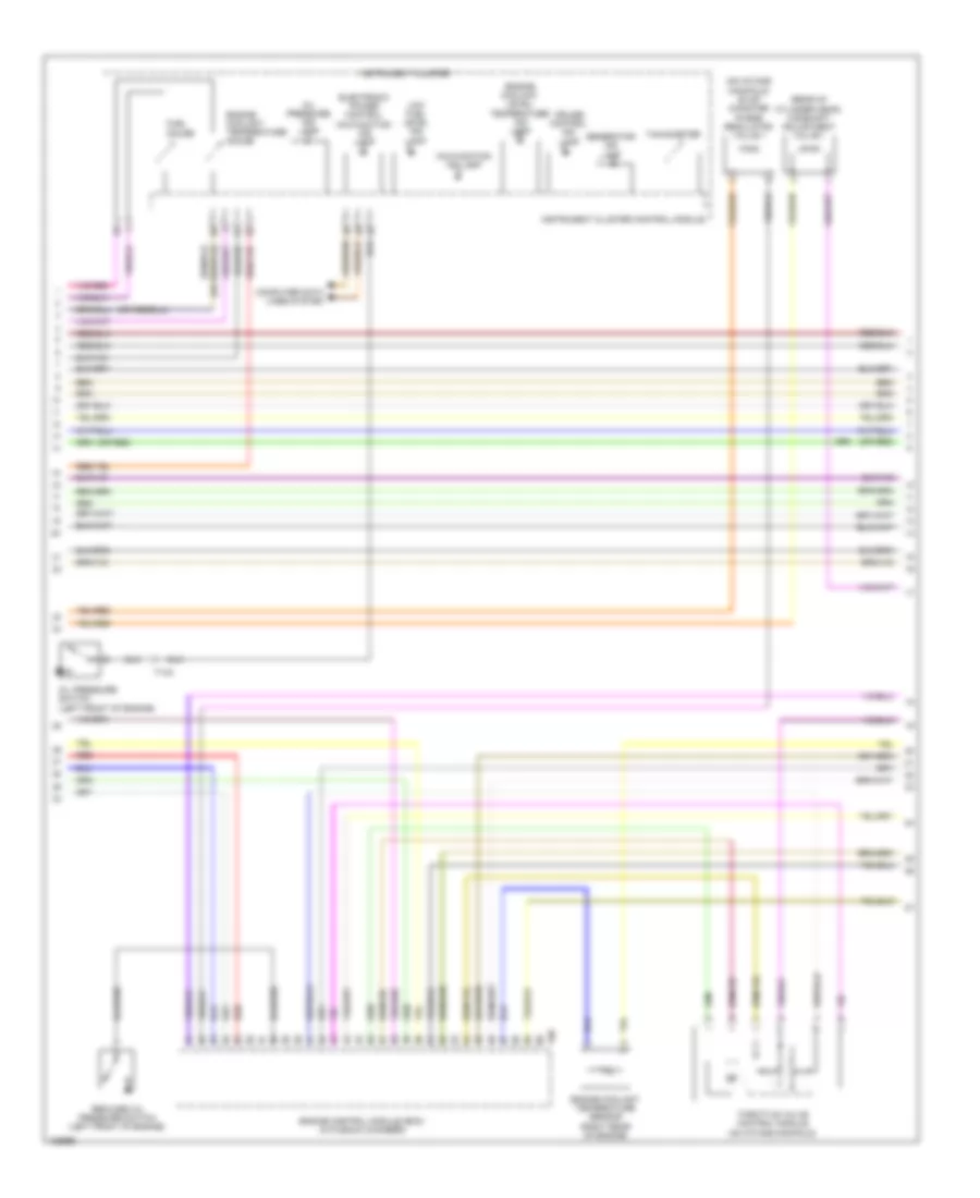
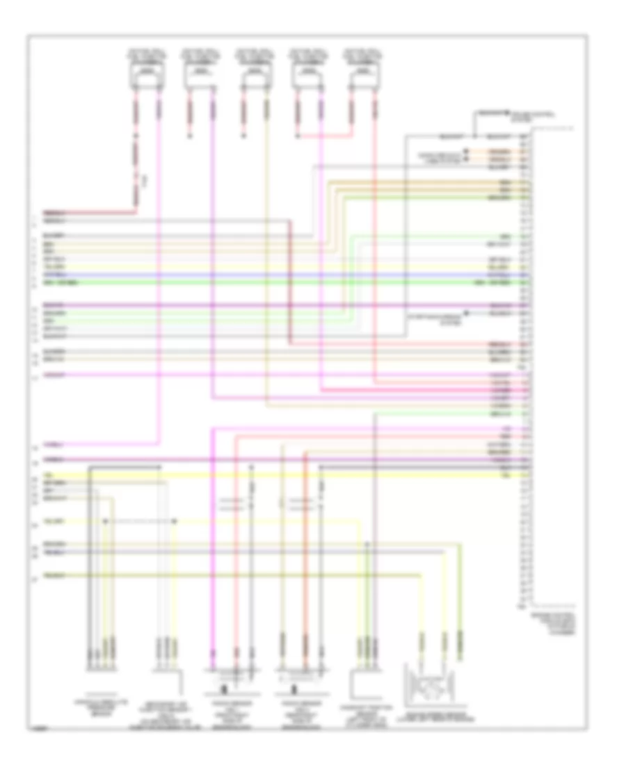
1.8L Turbo, Engine Performance Wiring Diagram (1 of 6) for Volkswagen Beetle 2014

List of elements for 1.8L Turbo, Engine Performance Wiring Diagram (1 of 6) for Volkswagen Beetle 2014:
- (left front of engine compt, on frame) g655
- (left rear of engine) secondary air injection pump motor
- Accelerator pedal position sensor
- Accelerator pedal position sensor 1 & 2 (above accelerator pedal)
- Accelerator pedal position sensor 2
- Charge air pressure sensor (on charge air tube)
- Cooling fans system
- Engine control module (in plenum chamber)
- Engine coolant temperature sensor (in radiator outlet)
- F21a
- F33
- F81
- F82
- F85
- Fuse 40a
- Fuse panel b (on e-box)
- G642 (left front of engine compt, on frame)
- Heated oxygen sensor
- Heater for oxygen sensor 1 after catalytic converter
- Hot at all times
- Nca
- Oxygen sensor 1 after catalytic converter
- Oxygen sensor 1 before catalytic converter
- Oxygen sensor after three way catalytic converter
- Oxygen sensor heater
- Secondary air injection pump relay
- Starting/ charging system
- T14a
- T91
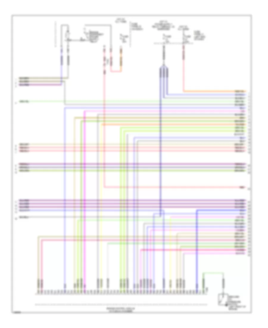
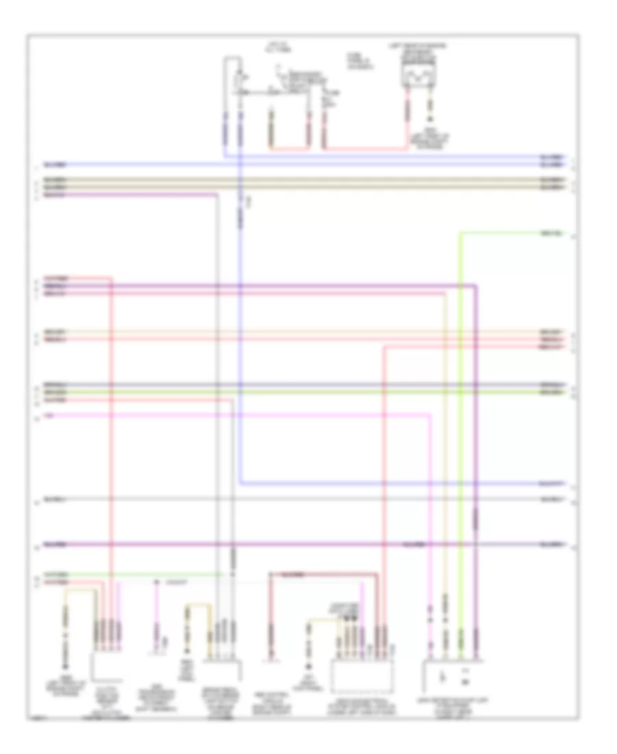
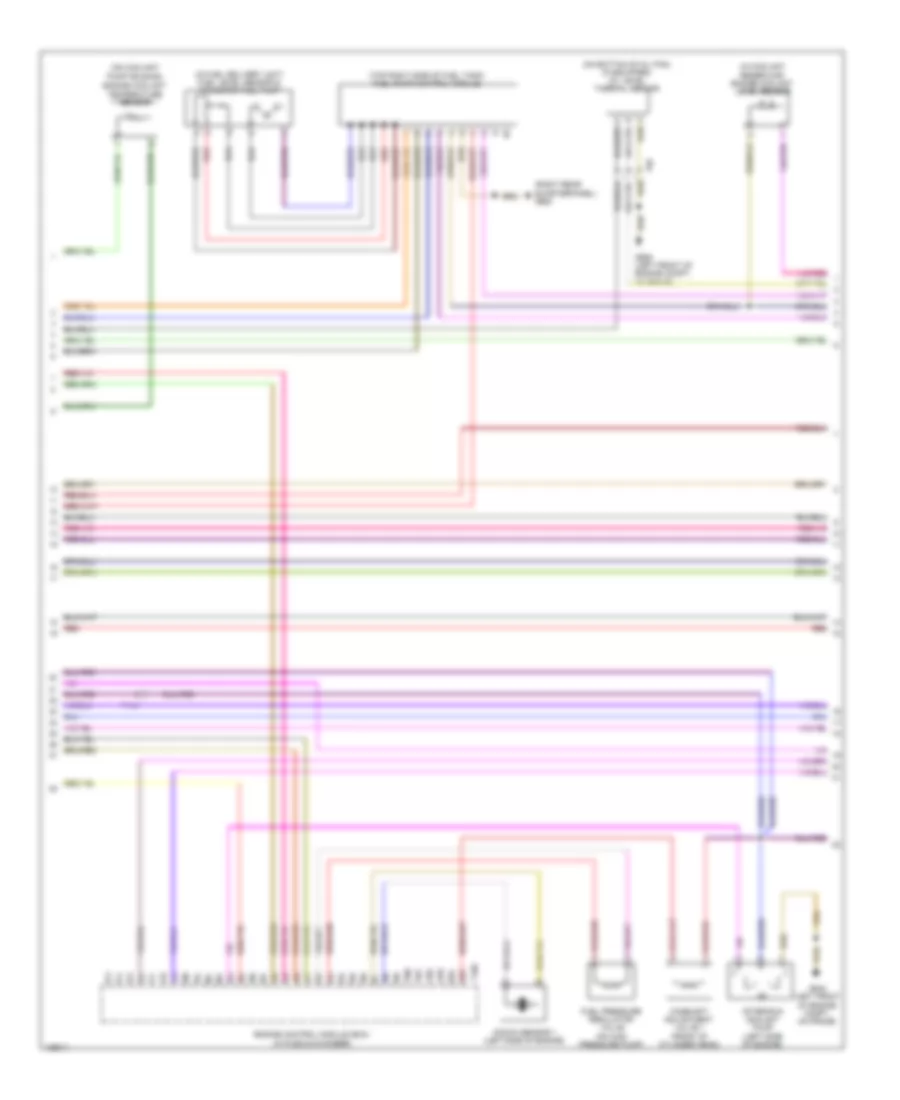
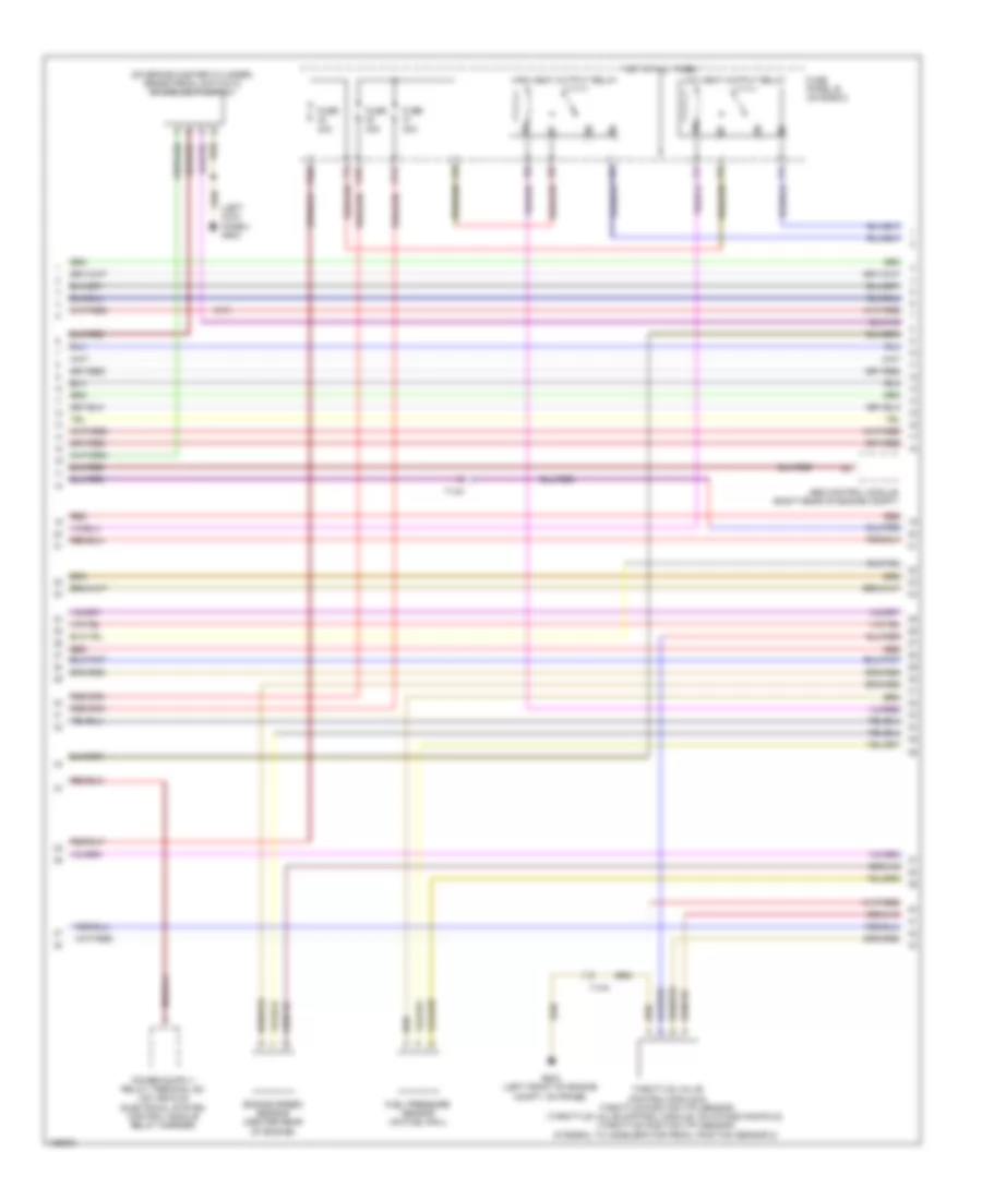
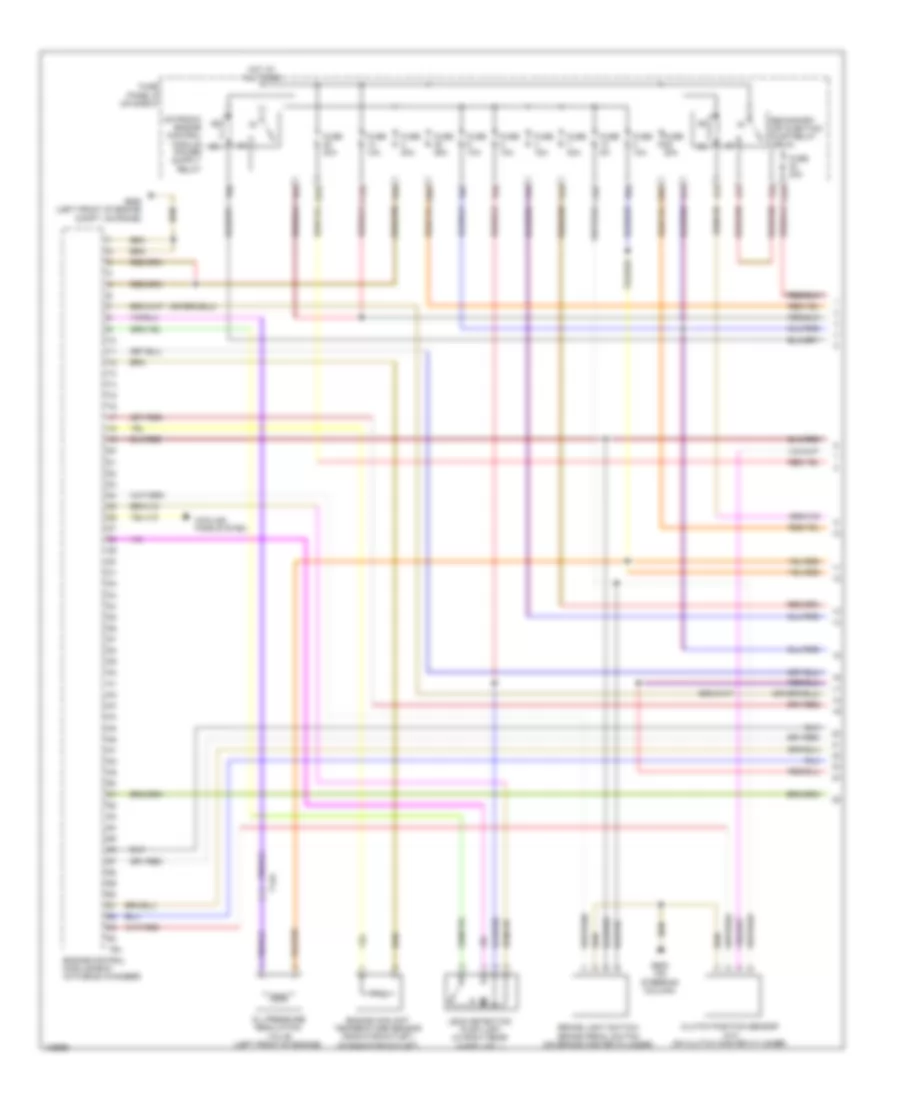
1.8L Turbo, Engine Performance Wiring Diagram (2 of 6) for Volkswagen Beetle 2014
List of elements for 1.8L Turbo, Engine Performance Wiring Diagram (2 of 6) for Volkswagen Beetle 2014:
- (rear of radiator
- (under left side of dash)
- Abs control module (right rear of engine compt)
- Brake pedal switch & brake lamp switch (on brake master cylinder)
- Clutch position sensor (m/t) (on clutch master cylinder)
- Computer data lines system
- Control module
- Coolant fan (fc)
- F10a
- F14a
- F2a
- F3a
- F5a
- F61
- F62
- F6a
- Fan assembly)
- Fuse 10a
- Fuse 30a
- Fuse 5a
- Fuse panel b (on e-box)
- G602 (left kick panel)
- G655 (left front of engine compt, on frame)
- Hot at all times
- Leak detection pump (if equipped) (in right rear wheelwell)
- T73a
- T73b
- Vehicle electrical system control module
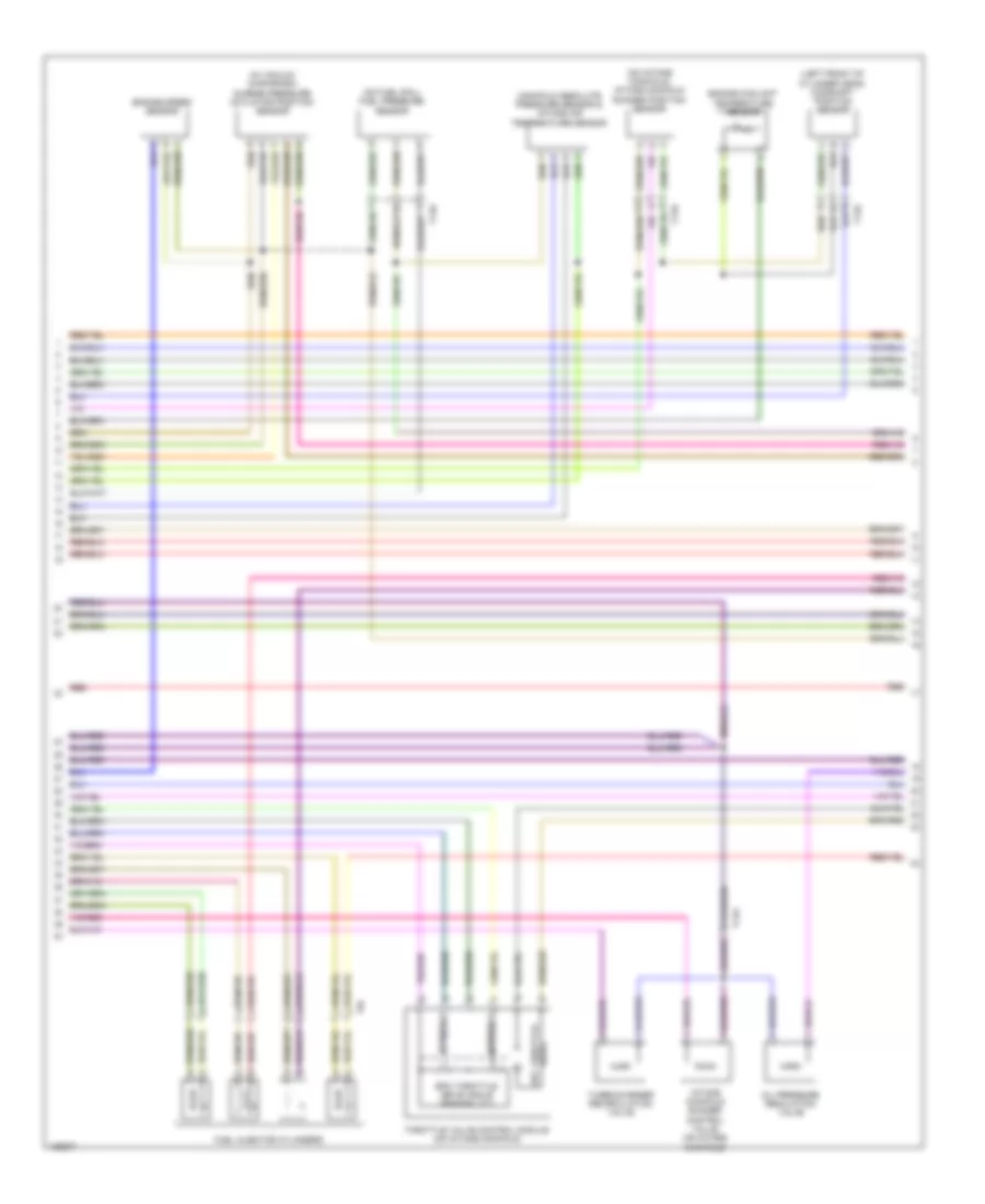
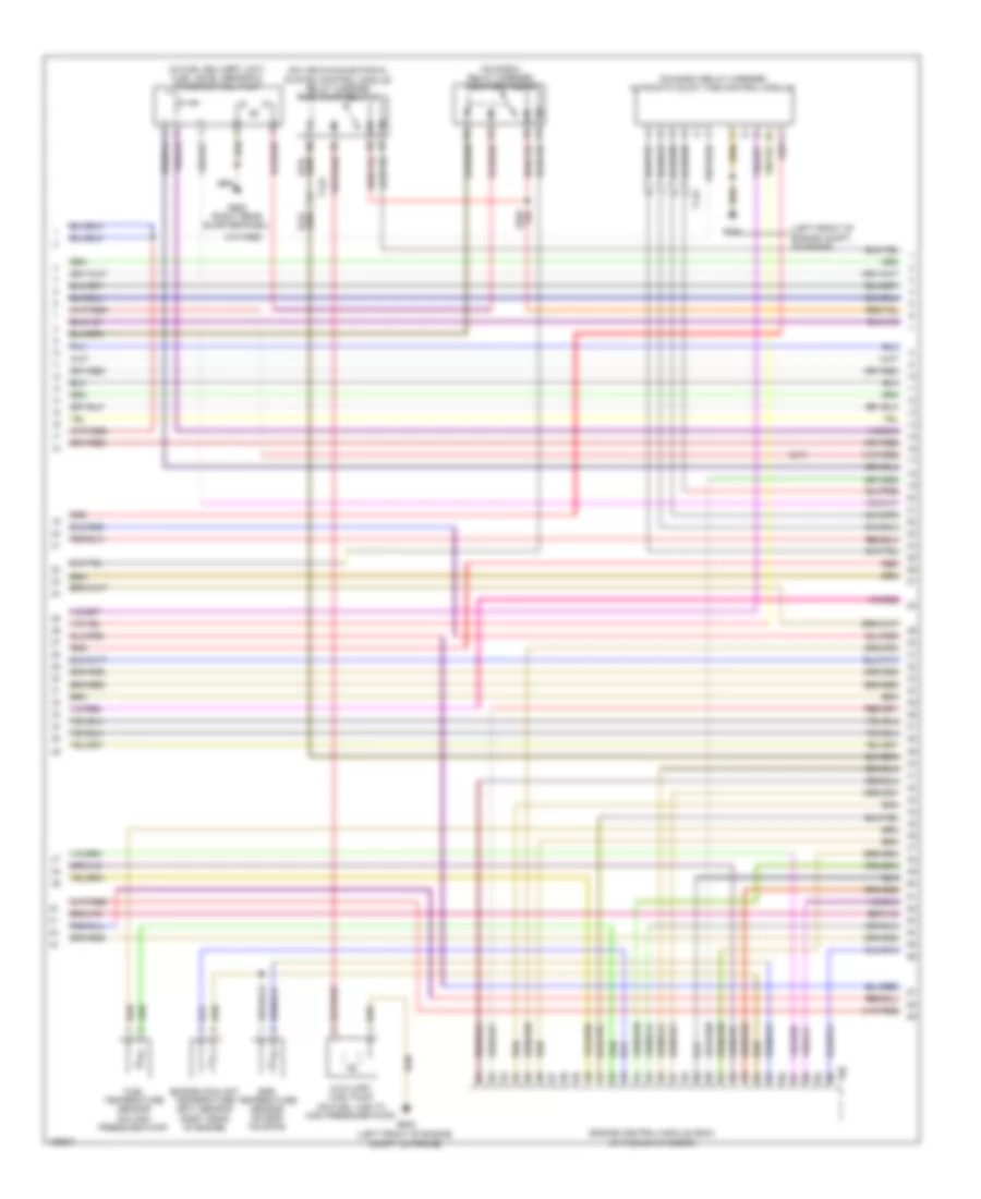
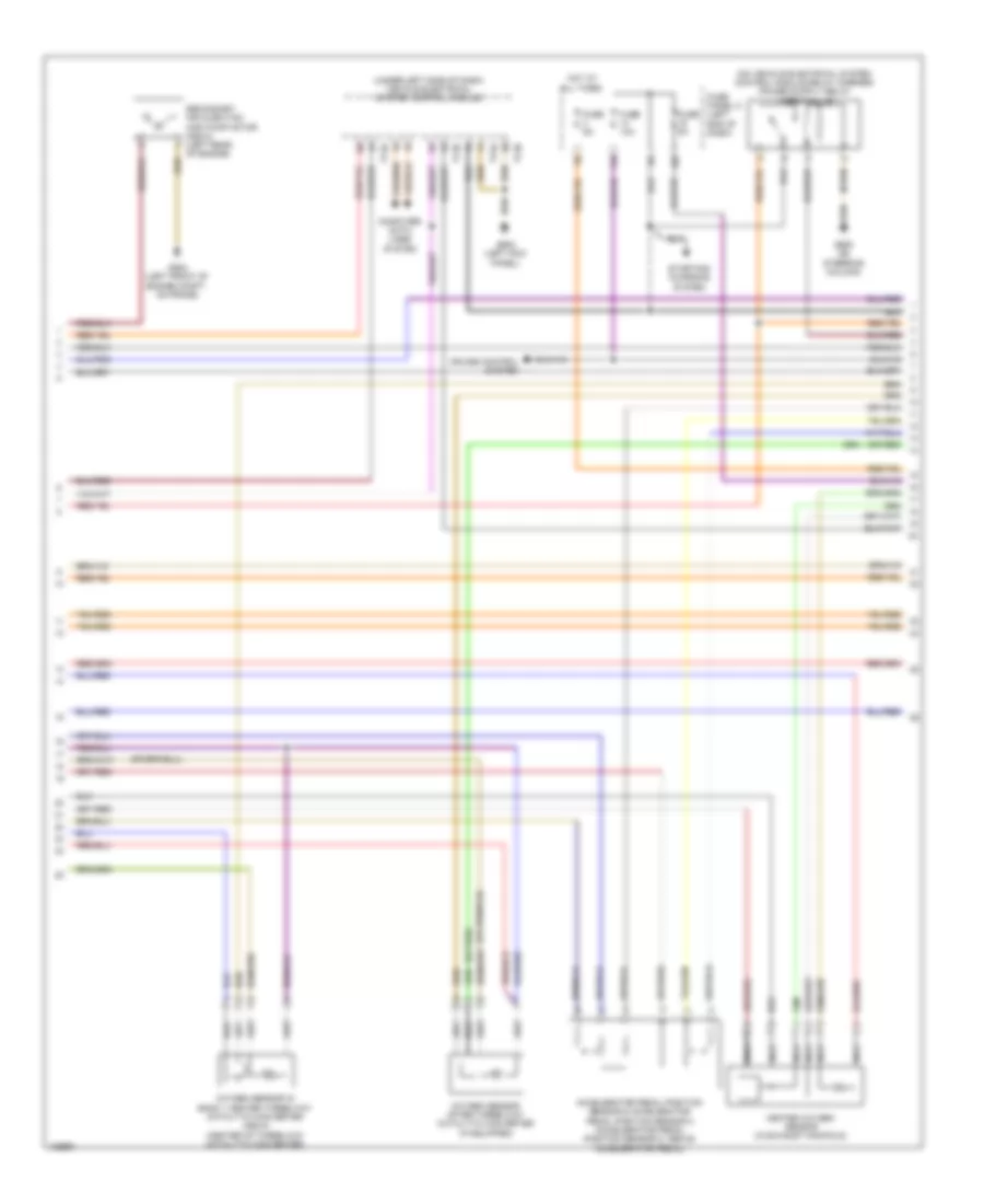
1.8L Turbo, Engine Performance Wiring Diagram (3 of 6) for Volkswagen Beetle 2014
List of elements for 1.8L Turbo, Engine Performance Wiring Diagram (3 of 6) for Volkswagen Beetle 2014:
- 14b
- 47b
- Engine control module (in plenum chamber)
- F28a
- F51
- F52
- F53
- F55
- Fuse 10a
- Fuse 20a
- Fuse panel b (on e-box)
- Fuse panel c (left end of dash)
- Hot at all times
- Red
- Reduced oil pressure switch (left front of engine)
- T105
- T14a
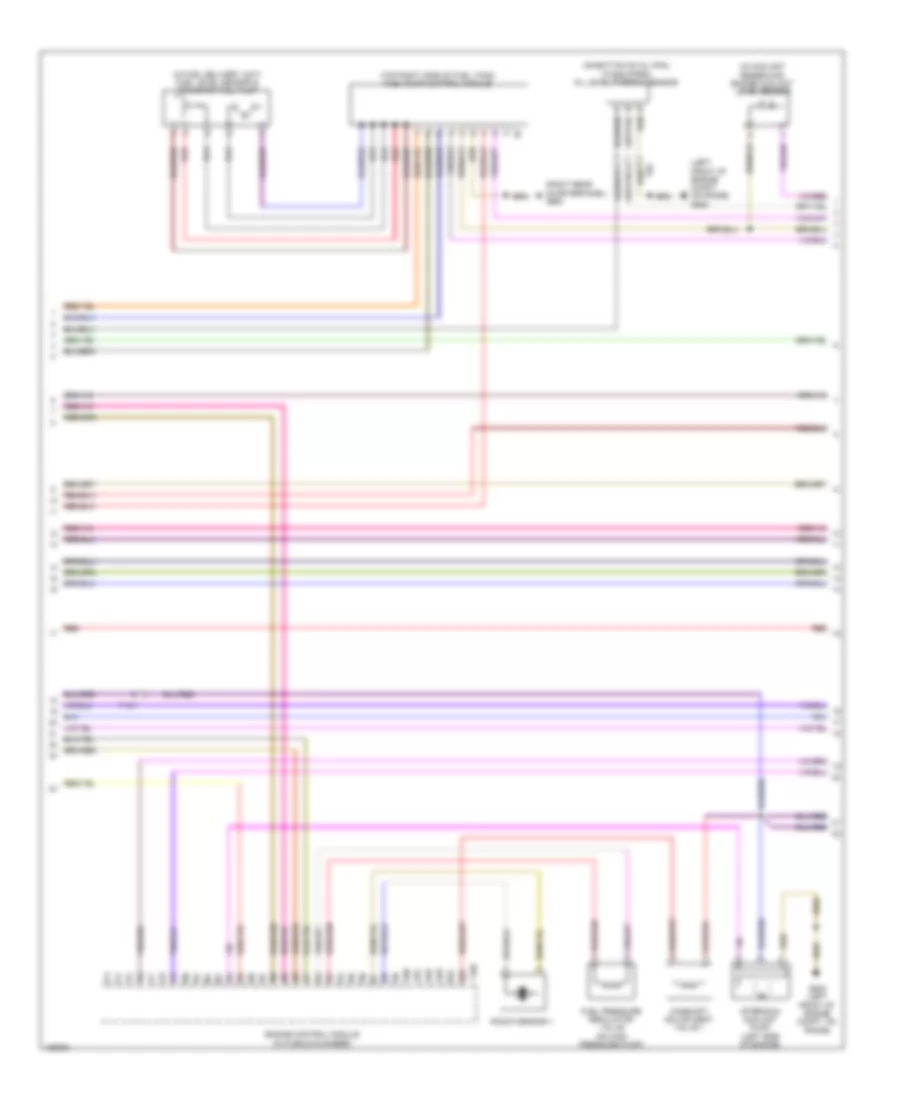
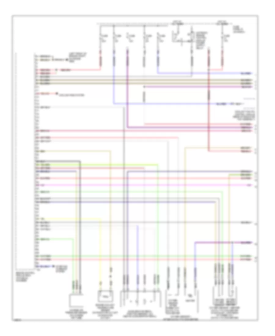
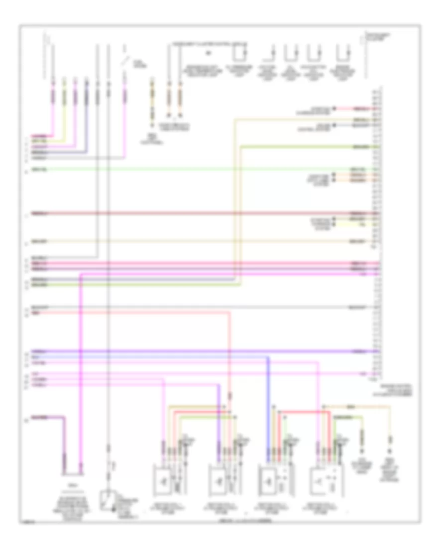
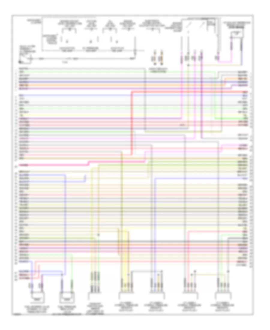
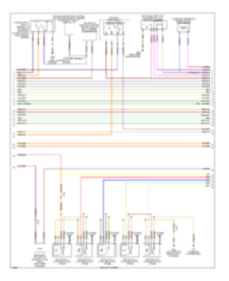
1.8L Turbo, Engine Performance Wiring Diagram (4 of 6) for Volkswagen Beetle 2014
List of elements for 1.8L Turbo, Engine Performance Wiring Diagram (4 of 6) for Volkswagen Beetle 2014:
- (in vacuum diaphragm) charge pressure actuator position sensor
- (left front of cylinder head) camshaft position sensor
- (on fuel rail) fuel pressure sensor
- (on intake manifold) intake manifold runner position sensor
- Drive epc throttle
- Engine coolant temperature sensor
- Engine speed sensor
- Epc throttle drive angle sensor 1 & 2
- Fuel injector cylinders
- Intake manifold runner control valve (on intake manifold)
- Manifold absolute pressure sensor & intake air temperature sensor
- Oil pressure regulation valve
- Red
- Sensor 1
- Sensor 2
- T14a
- T14e
- T8i
- Throttle valve control module (on intake manifold)
- Turbocharger recirculation valve
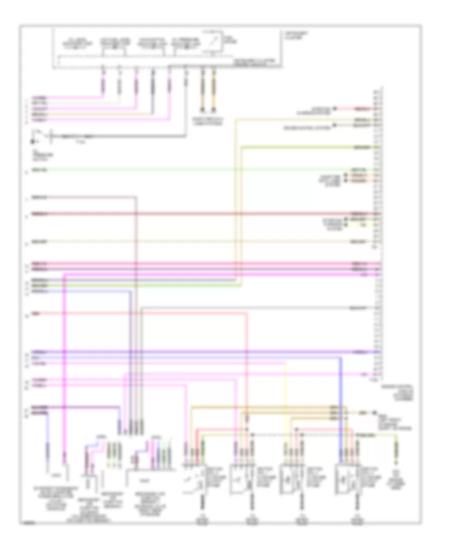
1.8L Turbo, Engine Performance Wiring Diagram (5 of 6) for Volkswagen Beetle 2014
List of elements for 1.8L Turbo, Engine Performance Wiring Diagram (5 of 6) for Volkswagen Beetle 2014:
- (in coolant reservoir) engine coolant level sensor
- (in fuel delivery unit) fuel level sensor & transfer fuel pump
- (left front of engine compt, on frame) g655
- (on bottom of oil pan) (if equipped) oil level thermal sensor
- (right rear quarterpanel) g663
- (top right side of fuel tank) fuel pump control module
- After-run coolant pump (left side of engine)
- Camshaft adjustment valve 1
- Engine control module (in plenum chamber)
- Fuel pressure regulator valve (on high pressure pump)
- G642 (left front of engine compt, on frame)
- Knock sensor 1
- Red
- T105
- T14a
- T6z
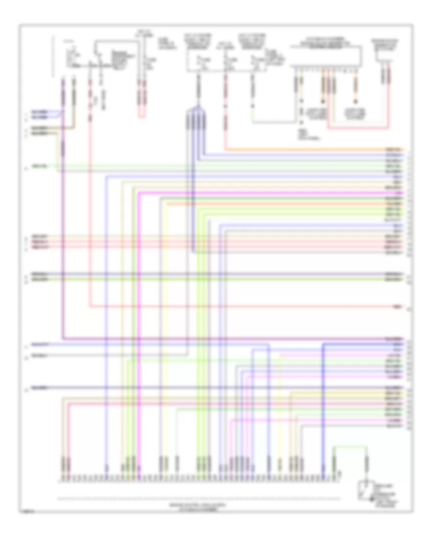
1.8L Turbo, Engine Performance Wiring Diagram (6 of 6) for Volkswagen Beetle 2014
List of elements for 1.8L Turbo, Engine Performance Wiring Diagram (6 of 6) for Volkswagen Beetle 2014:
- Computer data lines system
- Computer data lines systems
- Cpka
- Cpra
- Cruise control system
- Engine control module (in plenum chamber)
- Evaporative emission (evap) canister purge regulator valve 1 (on intake manifold)
- Fuel gauge
- G15 (on engine cylinder head)
- G642 (left front of engine compt, on frame)
- Ignition coil 1 w/ power output stage
- Ignition coil 2 w/ power output stage
- Ignition coil 3 w/ power output stage
- Ignition coil 4 w/ power output stage
- Instrument cluster
- Instrument cluster control module
- Low fuel level indicator lamp
- Malfunction indicator lamp
- Nca
- Oil level indicator lamp
- Oil pressure indicator lamp
- Oil pressure switch
- Red
- Secondary air injection sensor 1/ solenoid valve (right rear of engine)
- Secondary air injection sensor 2
- Secondary air injection solenoid valve/secondary air injection sensor 1
- Starting/ charging system
- T105
- T14a
- T91
- To spark plug
2.0L TURBO
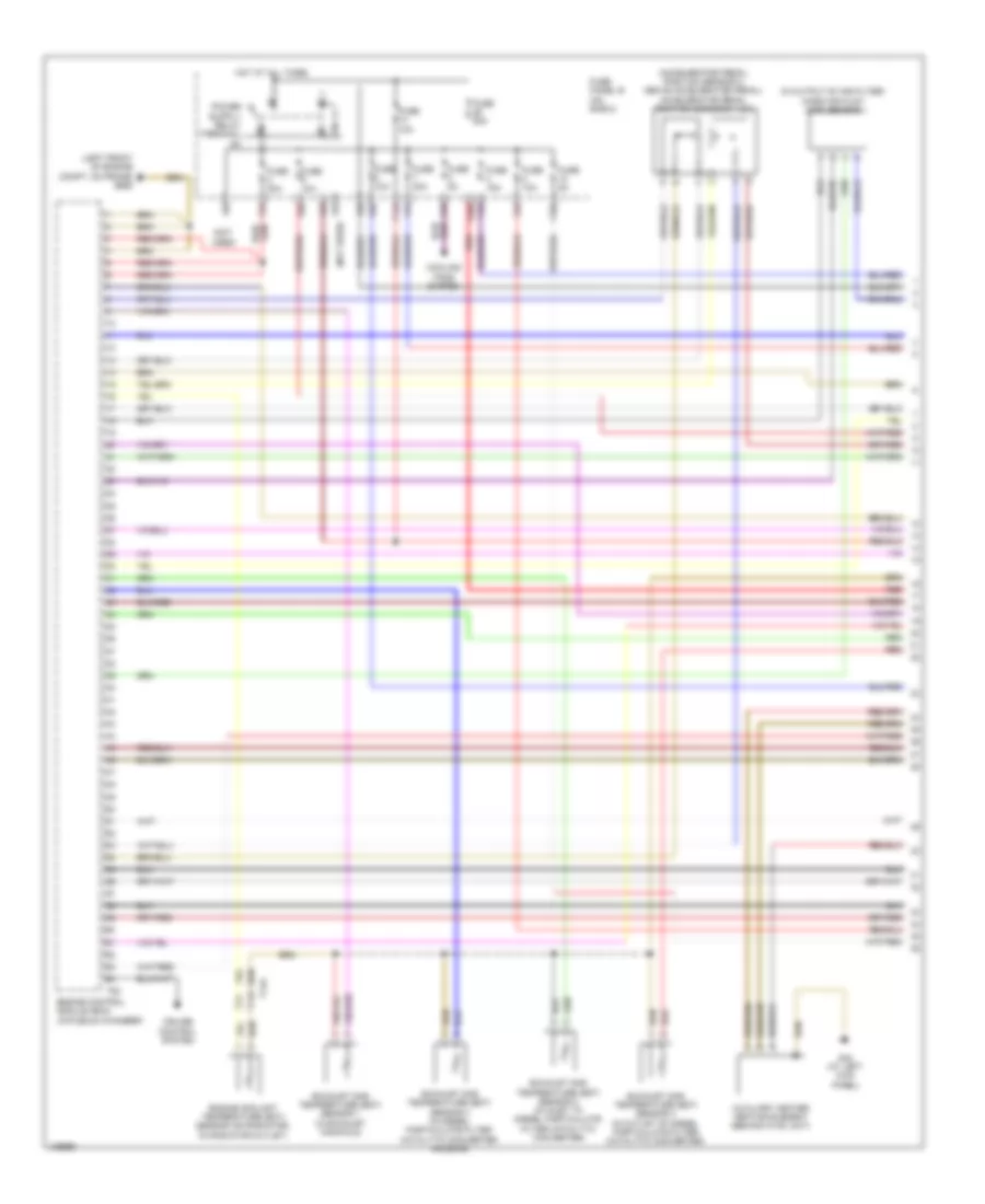
2.0L Turbo, Engine Performance Wiring Diagram (1 of 6) for Volkswagen Beetle 2014
List of elements for 2.0L Turbo, Engine Performance Wiring Diagram (1 of 6) for Volkswagen Beetle 2014:
- (left front of engine compt, on frame) g655
- Accelerator pedal position sensor 1 & 2 (above accelerator pedal)
- Charge air pressure sensor (on charge air tube)
- Coolant fan (fc) control module (rear of radiator fan assembly)
- Cooling fans system
- Engine control module (ecm) (in plenum chamber)
- Engine coolant temperature sensor (on radiator outlet) (in radiator outlet)
- F10a
- F14a
- F2a
- F3a
- F5a
- F61
- F62
- F6a
- Fuse 10a
- Fuse 30a
- Fuse 5a
- Fuse panel b (on e-box)
- Heated oxygen sensor
- Heater
- Hot at all times
- Nca
- Oxygen sensor 1 after catalytic converter
- Oxygen sensor 1 before catalytic converter (in exhaust, upstream of three way catalytic converter)
- Oxygen sensor after three way catalytic converter
- Oxygen sensor heater
- Starting/ charging system
- T91
2.0L Turbo, Engine Performance Wiring Diagram (2 of 6) for Volkswagen Beetle 2014
List of elements for 2.0L Turbo, Engine Performance Wiring Diagram (2 of 6) for Volkswagen Beetle 2014:
- (left rear of engine)
- (under left side of dash)
- Abs control
- Brake pedal switch/brake lamp switch (on brake master cylinder)
- Clutch position sensor (m/t) (on clutch master cylinder)
- Computer data lines system
- Dsg transmission mechatronic (in direct shift gearbox)
- F21a
- F33
- F81
- F82
- F85
- Fuse 50a
- Fuse panel b (on e-box)
- G47 (right kick panel)
- G602 (left kick panel)
- G642 (left front of engine compt, on frame)
- G655 (left front of engine compt, on frame)
- Hot at all times
- Leak detection pump (ldp) (if equipped) (in right rear wheelwell)
- Module (right rear of engine compt)
- Secondary air injection pump motor
- Secondary air injection pump relay
- T14a
- T20e
- T73a
- T73b
- Vehicle electrical system control module
2.0L Turbo, Engine Performance Wiring Diagram (3 of 6) for Volkswagen Beetle 2014
List of elements for 2.0L Turbo, Engine Performance Wiring Diagram (3 of 6) for Volkswagen Beetle 2014:
- (in plenum chamber) engine sound generator control module
- (not used)
- 14b
- 15b
- 47b
- 87a
- Computer data lines systems
- Engine control module (ecm) (in plenum chamber)
- Engine sound generator actuator 1
- F28a
- F51
- F52
- F53
- F54
- F55
- Fuse 10a
- Fuse 20a
- Fuse 5a
- Fuse panel b (on e-box)
- Fuse panel c (left end of dash)
- G602 (left kick panel)
- Hot at all times
- Red
- Reduced oil pressure switch (left front of engine)
- T105
- T14a
2.0L Turbo, Engine Performance Wiring Diagram (4 of 6) for Volkswagen Beetle 2014
List of elements for 2.0L Turbo, Engine Performance Wiring Diagram (4 of 6) for Volkswagen Beetle 2014:
- (center rear of engine)
- (in vacuum diaphragm) charge pressure actuator position sensor
- (left front of cylinder head) camshaft position sensor
- (on fuel rail) fuel pressure sensor
- (on intake manifold) intake manifold runner position sensor
- (right rear of engine) secondary air injection sensor 1/ solenoid valve
- (right rear of engine) secondary air injection solenoid valve
- Cpla
- Cppa
- Engine speed sensor
- Fuel injector cylinders (on fuel rail)
- Intake manifold runner control valve (on intake manifold)
- Manifold absolute pressure sensor & intake air temperature sensor
- Oil pressure regulation valve (inside oil pan)
- Red
- Secondary air injection sensor 2
- Sensor 1
- Sensor 2
- T14a
- T14e
- T8i
- Throttle drive
- Throttle valve control module (on intake manifold)
- Turbocharger recirculation valve (on turbocharger)
2.0L Turbo, Engine Performance Wiring Diagram (5 of 6) for Volkswagen Beetle 2014
List of elements for 2.0L Turbo, Engine Performance Wiring Diagram (5 of 6) for Volkswagen Beetle 2014:
- (in coolant reservoir) engine coolant level sensor
- (in fuel delivery unit) fuel level sensor & transfer fuel pump
- (on bottom of oil pan) (if equipped) oil level thermal sensor
- (on coolant pump housing)
- (right rear quarterpanel) g663
- (top right side of fuel tank) fuel pump control module
- After-run coolant pump (left side of engine)
- Camshaft adjustment valve 1 (front of cylinder head)
- Engine control module (ecm) (in plenum chamber)
- Engine coolant temperature sensor
- Fuel pressure regulator valve (on high pressure pump)
- G642 (left front of engine compt, on frame)
- G655 (left front of engine compt, on frame)
- Knock sensor 1 (left side of engine)
- Red
- T105
- T14a
- T6z
2.0L Turbo, Engine Performance Wiring Diagram (6 of 6) for Volkswagen Beetle 2014
List of elements for 2.0L Turbo, Engine Performance Wiring Diagram (6 of 6) for Volkswagen Beetle 2014:
- (above 1, 2, 3 & 4 cylinders)
- Computer data lines system
- Computer data lines systems
- Cruise control system
- Engine control module (ecm) (in plenum chamber)
- Engine coolant level/temperature indicator lamp
- Engine electronics indicator lamp
- Evaporative emission (evap) canister purge regulator valve 1 (on intake manifold)
- Fuel gauge
- G15 (on engine cylinder head)
- G602 (left kick panel)
- G642 (left front of engine compt, on frame)
- Ignition coil 1 w/ power output stage
- Ignition coil 2 w/ power output stage
- Ignition coil 3 w/ power output stage
- Ignition coil 4 w/ power output stage
- Instrument cluster
- Instrument cluster control module
- Low fuel level indicator lamp
- Malfunction (mil) indicator lamp
- Nca
- Oil level indicator lamp
- Oil pressure indicator lamp
- Oil pressure switch (on oil filter assembly)
- Red
- Starting/ charging system
- T105
- T14a
- T91
- To spark plug
2.0L TURBO DIESEL
2.0L Turbo Diesel, Engine Performance Wiring Diagram (1 of 6) for Volkswagen Beetle 2014
List of elements for 2.0L Turbo Diesel, Engine Performance Wiring Diagram (1 of 6) for Volkswagen Beetle 2014:
- (accelerator pedal position sensor 2: above accelerator pedal) accelerator pedal position sensors 1 & 2
- (in output of air filter) mass air flow (maf) sensor
- (left front of engine compt, on frame) g655
- (not used)
- Auxiliary heater heating element (behind hvac unit)
- Cooling fans system
- Cruise control system
- Engine control module (ecm) (in plenum chamber)
- Engine coolant temperature (ect) sensor (on radiator) (in radiator outlet)
- Exhaust gas temperature (egt) sensor 1 (in exhaust manifold)
- Exhaust gas temperature (egt) sensor 2 (in inlet to diesel particulate filter catalytic converter)
- Exhaust gas temperature (egt) sensor 3 (in diesel particulate filter catalytic converter housing)
- Exhaust gas temperature (egt) sensor 4 (in outlet of diesel particulate filter catalytic converter)
- F10a
- F14a
- F26a
- F2a
- F3a
- F4a
- F5a
- F61
- F62
- F65
- F67
- F7a
- F8a
- F9a
- Fuse 10a
- Fuse 15a
- Fuse 20a
- Fuse 30a
- Fuse 50a
- Fuse 5a
- Fuse panel b (on e-box)
- G44 (at left kick panel)
- Hot at all times
- Red
- T14a
- T94
2.0L Turbo Diesel, Engine Performance Wiring Diagram (2 of 6) for Volkswagen Beetle 2014
List of elements for 2.0L Turbo Diesel, Engine Performance Wiring Diagram (2 of 6) for Volkswagen Beetle 2014:
- (in exhaust, behind three way catalytic converter) oxygen sensor (o2s) behind three way catalytic converter
- (in exhaust, upstream of three way catalytic converter) heated oxygen sensor & oxygen sensor heater
- (left kick panel) g602
- (on clutch master cylinder) (m/t) clutch position sensor
- (under left side of dash) vehicle electrical system control module
- Computer data lines system
- Converter box (on vehicle electrical system control module relay carrier)
- Differential pressure sensor
- Egr potentiometer & egr vacuum regulator solenoid valve (egr vacuum regulator solenoid valve: intake manifold input) (egr potentiometer: integral w/ egr vacuum regulator solenoid)
- Exhaust door control unit
- Exhaust pressure sensor 1 (bolted to auxiliary fuel pump)
- Nca
- Red
- T14a
- T73a
- T73b
2.0L Turbo Diesel, Engine Performance Wiring Diagram (3 of 6) for Volkswagen Beetle 2014
List of elements for 2.0L Turbo Diesel, Engine Performance Wiring Diagram (3 of 6) for Volkswagen Beetle 2014:
- (left kick panel) g602
- (m/t)
- (on brake master cylinder) brake pedal switch & brake light switch
- Abs control module (right rear of engine compt)
- Engine speed sensor (center rear of engine)
- F21a
- F22a
- F32a
- F33
- F34
- F71
- F72
- F75
- F81
- F82
- F85
- Fuel pressure sensor (on fuel rail)
- Fuse 40a
- Fuse panel b (on e-box)
- G642 (left front of engine compt, on frame)
- High heat output relay
- Hot at all times
- Low heat output relay
- Red
- T14a
- Throttle valve control module & throttle position (tp) sensor (throttle valve control module: on intake manifold) (throttle position (tp) sensor: integral to accelerator pedal position sensor 2)
2.0L Turbo Diesel, Engine Performance Wiring Diagram (4 of 6) for Volkswagen Beetle 2014
List of elements for 2.0L Turbo Diesel, Engine Performance Wiring Diagram (4 of 6) for Volkswagen Beetle 2014:
- (in fuel delivery unit) fuel level sensor & transfer fuel pump
- (left front of engine compt, on frame)
- (m/t)
- (on e-box relay carrier) automatic glow time control module
- (on e-box relay carrier) fuel pump relay
- (on vehicle electrical system control module relay carrier) fuel pump relay 2
- Auxiliary fuel pump (on fuel line to high pressure pump)
- Compt, on frame)
- Egr temperature sensor (on egr housing)
- Engine control module (ecm) (in plenum chamber)
- Engine coolant temperature (ect) sensor (right rear of engine)
- Fuel temperature sensor (on high pressure pump)
- G642
- G642 (left front of engine
- G663 (right rear quarterpanel)
- Red
- T14a
- T60
2.0L Turbo Diesel, Engine Performance Wiring Diagram (5 of 6) for Volkswagen Beetle 2014
List of elements for 2.0L Turbo Diesel, Engine Performance Wiring Diagram (5 of 6) for Volkswagen Beetle 2014:
- (in coolant reservoir) engine coolant level sensor
- (m/t)
- (on oil filter assembly) oil pressure switch
- Camshaft position (cmp) sensor (left front of cylinder head)
- Computer data lines system
- Cylinder 1 internal pressure sensor & glow plug 1
- Cylinder 2 internal pressure sensor & glow plug 2
- Cylinder 3 internal pressure sensor & glow plug 3
- Cylinder 4 internal pressure sensor & glow plug 4
- Electronic power control malfunction ind lamp
- Engine coolant level/temperature ind lamp
- Engine coolant temperature gauge
- Engine electronics ind lamp
- Fuel gauge
- Fuel metering valve (integral w/ high pressure pump)
- Fuel pressure regulator valve (on high pressure pump)
- Glow plug ind lamp
- Instrument cluster
- Instrument cluster control module
- Low fuel level ind lamp
- Malfunction ind lamp
- Nca
- Oil level ind lamp
- Oil pressure ind lamp
- Red
- T14a
2.0L Turbo Diesel, Engine Performance Wiring Diagram (6 of 6) for Volkswagen Beetle 2014
List of elements for 2.0L Turbo Diesel, Engine Performance Wiring Diagram (6 of 6) for Volkswagen Beetle 2014:
- (charge air pressure sensor: on charge air tube) (intake air temperature (iat) sensor: integrated w/ charge air pressure sensor) intake air temperature (iat) & charge air pressure sensor
- (in turbocharger intake scoop) (if equipped) positive crankcase ventilation (pcv) heating element
- 14b
- 15b
- 16b
- 47b
- Charge pressure actuator position sensor (in vacuum diaphragm)
- Computer data lines system
- Cooling fans system
- Cylinder fuel injectors (on fuel rail)
- Engine control module (ecm) (in plenum chamber)
- Exhaust gas recirculation (egr) position sensor 2 & egr valve 2 (egr valve 2: on egr housing)
- Fuse 10a
- Fuse 20a
- Fuse 5a
- Fuse panel c (left end of dash)
- Hot at all times
- Intake manifold runner position sensor & intake flap motor (intake manifold runner position sensor: on intake manifold) (intake flap motor: in intake manifold)
- M/t
- Red
- Starting/charging system
- T14a
- T4bw
- T60
- T94
- Wastegate bypass regulator valve (on turbocharger)
2.5L
2.5L, Engine Performance Wiring Diagram (1 of 5) for Volkswagen Beetle 2014
List of elements for 2.5L, Engine Performance Wiring Diagram (1 of 5) for Volkswagen Beetle 2014:
- Brake light switch/ brake pedal switch (on brake master cylinder)
- Clutch position sensor (m/t) (on clutch master cylinder)
- Cooling fans system
- Engine control module (ecm) (in plenum chamber)
- Engine coolant temperature sensor (radiator outlet) (in radiator outlet)
- F10a
- F14a
- F20a
- F25a
- F28a
- F2a
- F32a
- F34
- F4a
- F5a
- F61
- F62
- F6a
- F71
- F72
- F75
- F7a
- F8a
- Fuse 10a
- Fuse 15a
- Fuse 20a
- Fuse 25a
- Fuse 30a
- Fuse 40a
- Fuse 5a
- Fuse panel b (on e-box)
- G605 (on steering column)
- G655 (left front of engine compt, on frame)
- Hot at all times
- Leak detection pump (ldp) (in right rear wheelwell)
- Oil pressure regulation valve (left front of engine)
- Secondary air injection pump relay (cbua)
- T14a
- T94
2.5L, Engine Performance Wiring Diagram (2 of 5) for Volkswagen Beetle 2014
List of elements for 2.5L, Engine Performance Wiring Diagram (2 of 5) for Volkswagen Beetle 2014:
- (or red)
- (under left side of dash) vehicle electrical system control module
- 14b
- 16b
- Accelerator pedal position sensor & accelerator pedal position sensor 2 (accelerator pedal position sensor 2: above accelerator pedal)
- Computer data lines system
- Cruise control system
- Fuse 10a
- Fuse 5a
- Fuse panel c (left end of dash)
- G602 (left kick panel)
- G605 (on steering column)
- G642 (left front of engine compt, on frame)
- Heated oxygen sensor (in exhaust manifold)
- Hot at all times
- Nca
- Oxygen sensor after three way catalytic converter (if equipped)
- Oxygen sensor in bank 1 center three way catalytic converter (cbua) (center of three way catalytic converter)
- Secondary air injection (air) pump motor (cbua) (left rear of engine)
- Starting/ charging system
- T73a
- T73b
2.5L, Engine Performance Wiring Diagram (3 of 5) for Volkswagen Beetle 2014
List of elements for 2.5L, Engine Performance Wiring Diagram (3 of 5) for Volkswagen Beetle 2014:
- (above cylinders)
- (in coolant reservoir) engine coolant level sensor
- (in fuel delivery unit) transfer fuel pump/ fuel level sensor
- (on e-box) fuse panel b
- (on vehicle electrical system control module relay carrier) converter box
- (or red)
- F51
- F52
- F53
- F55
- Fuel pump relay
- G15 (on engine cylinder head)
- G605 (on steering column)
- G642 (left front of engine compt, on frame)
- G663 (right rear quarterpanel)
- Ignition coil 1 w/ power output stage
- Ignition coil 2 w/ power output stage
- Ignition coil 3 w/ power output stage
- Ignition coil 4 w/ power output stage
- Ignition coil 5 w/ power output stage
- Nca
- Power distribution system
- Red
- Secondary air injection solenoid valve (cbua) (right rear of engine)
- T14a
- To spark plug
2.5L, Engine Performance Wiring Diagram (4 of 5) for Volkswagen Beetle 2014
List of elements for 2.5L, Engine Performance Wiring Diagram (4 of 5) for Volkswagen Beetle 2014:
- (on intake manifold) evap canister purge regulator valve 1
- (or red)
- (rear of cylinder head) camshaft adjustment valve 1
- Computer data lines system
- Cruise control ind lamp
- Electronic power control malfunction ind lamp
- Engine control module (ecm) (in plenum chamber)
- Engine coolant level/ temperature ind lamp
- Engine coolant temperature gauge
- Engine coolant temperature sensor (right rear of engine)
- Fuel gauge
- Generator ind lamp
- Instrument cluster
- Instrument cluster control module
- Low fuel level ind lamp
- Malfunction ind lamp
- Oil pressure ind lamp
- Oil pressure switch (left front of engine)
- Red
- Reduced oil pressure switch (left front of engine)
- T14a
- T60
- Tachometer
- Throttle valve control module (on intake manifold)
2.5L, Engine Performance Wiring Diagram (5 of 5) for Volkswagen Beetle 2014
List of elements for 2.5L, Engine Performance Wiring Diagram (5 of 5) for Volkswagen Beetle 2014:
- (on fuel rail) fuel injector cylinder 1
- (on fuel rail) fuel injector cylinder 2
- (on fuel rail) fuel injector cylinder 3
- (on fuel rail) fuel injector cylinder 4
- (on fuel rail) fuel injector cylinder 5
- (or red)
- Camshaft position sensor (left front of cylinder head)
- Computer data lines system
- Cruise control system
- Engine control module (ecm) (in plenum chamber)
- Engine speed sensor (lower left rear of engine)
- Knock sensor (ks) 1 (front right side of engine block)
- Knock sensor (ks) 2 (rear right side of engine block)
- Manifold absolute pressure sensor
- Nca
- Red
- Secondary air injection sensor 1 (cbua) (on secondary air injection solenoid valve)
- Starting/charging system
- T14a
- T60
- T94