ENGINE PERFORMANCE
1.9L TURBO DIESEL
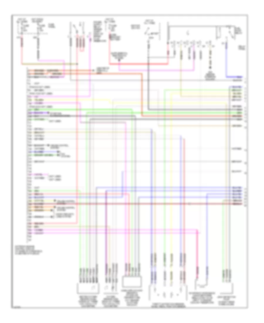
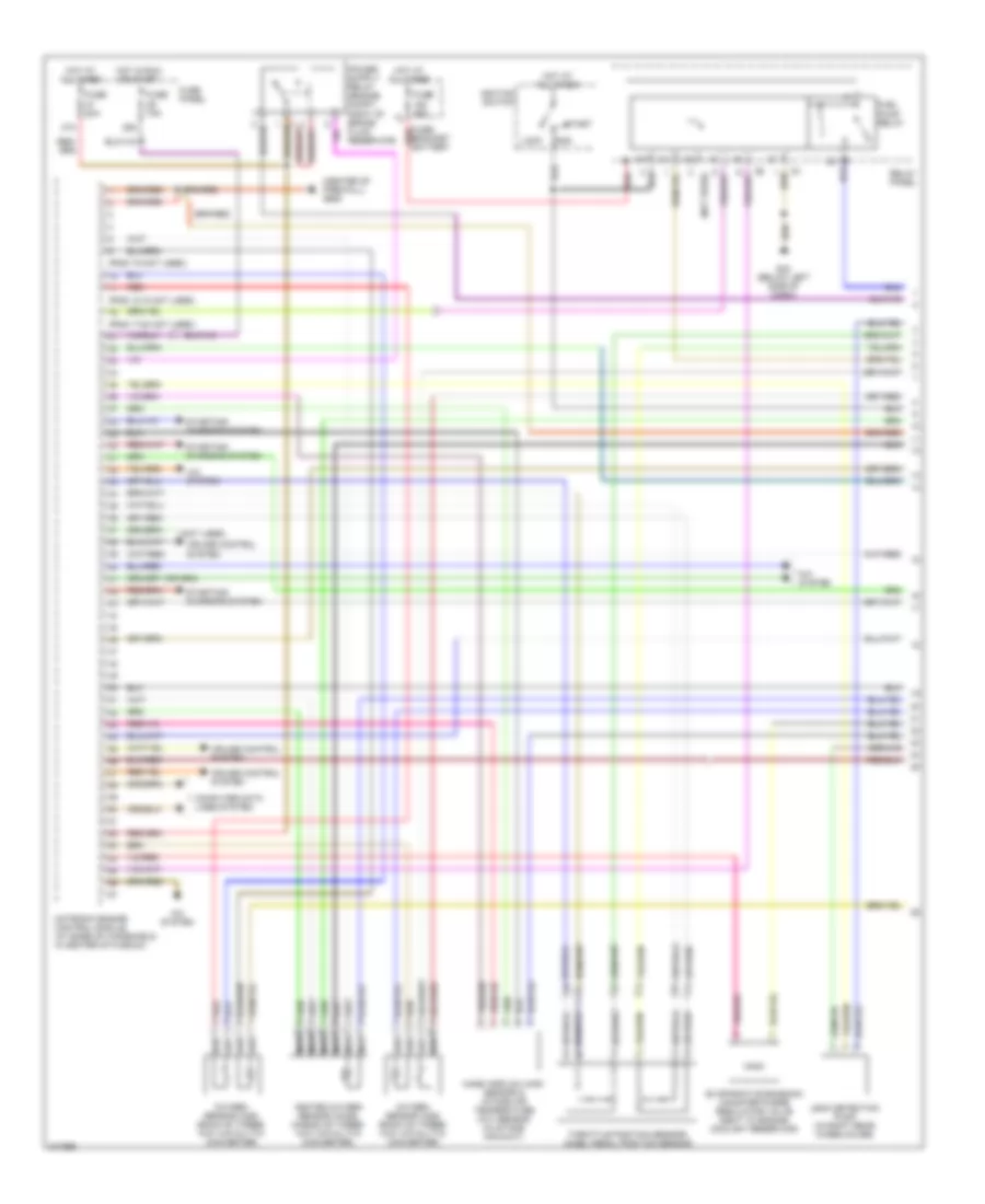
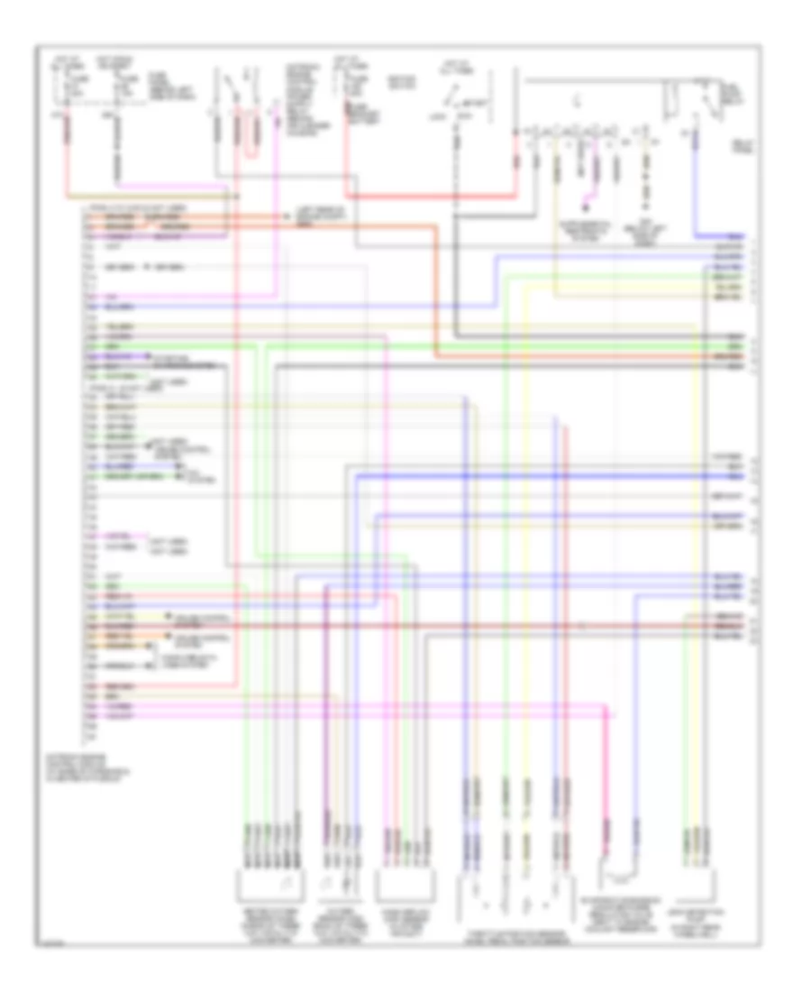
1.9L Turbo Diesel, Engine Performance Wiring Diagram (1 of 4) for Volkswagen Golf GL 2006

List of elements for 1.9L Turbo Diesel, Engine Performance Wiring Diagram (1 of 4) for Volkswagen Golf GL 2006:
- (not used)
- 29a
- 37a
- A/c & cooling fans system
- A/c system
- Acc
- Clutch pedal switch (above clutch pedal)
- Cruise control system
- Diesel direct fuel injection (dfi) engine control module (ecm) (base of windshield, center of plenum)
- Exterior lights system
- Fuse 10a
- Fuse 15a
- Fuse 30a
- Fuse 5a
- Fuse bracket/ bracket (behind battery)
- Fuse panel (behind left side of dash)
- Fuse s176 110a
- G608 (left rear of eng compt)
- G608 (left rear of engine compt)
- Heated oxygen sensor (below vehicle, front of 3-way catalytic conv)
- Hot at all times
- Ignition switch
- Lock
- M/t
- Mass airflow (maf) sensor (right side of air cleaner housing)
- Nca
- Positive crankcase ventilation (pcv) heating element (in pcv hose)
- Red
- Relay panel
- Run
- Start
- T94
- Throttle position (tp) sensor/ closed throttle position (ctp) switch/kickdown switch (above accelerator pedal)
- W/ pcv heating element
- W/o pcv heating element
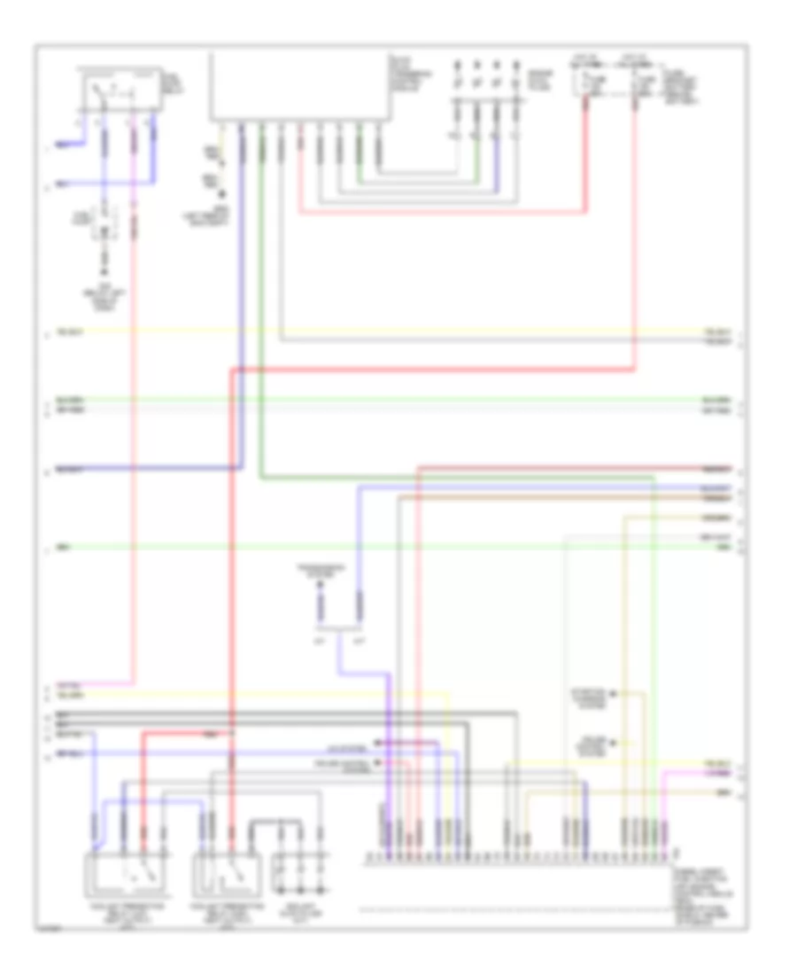
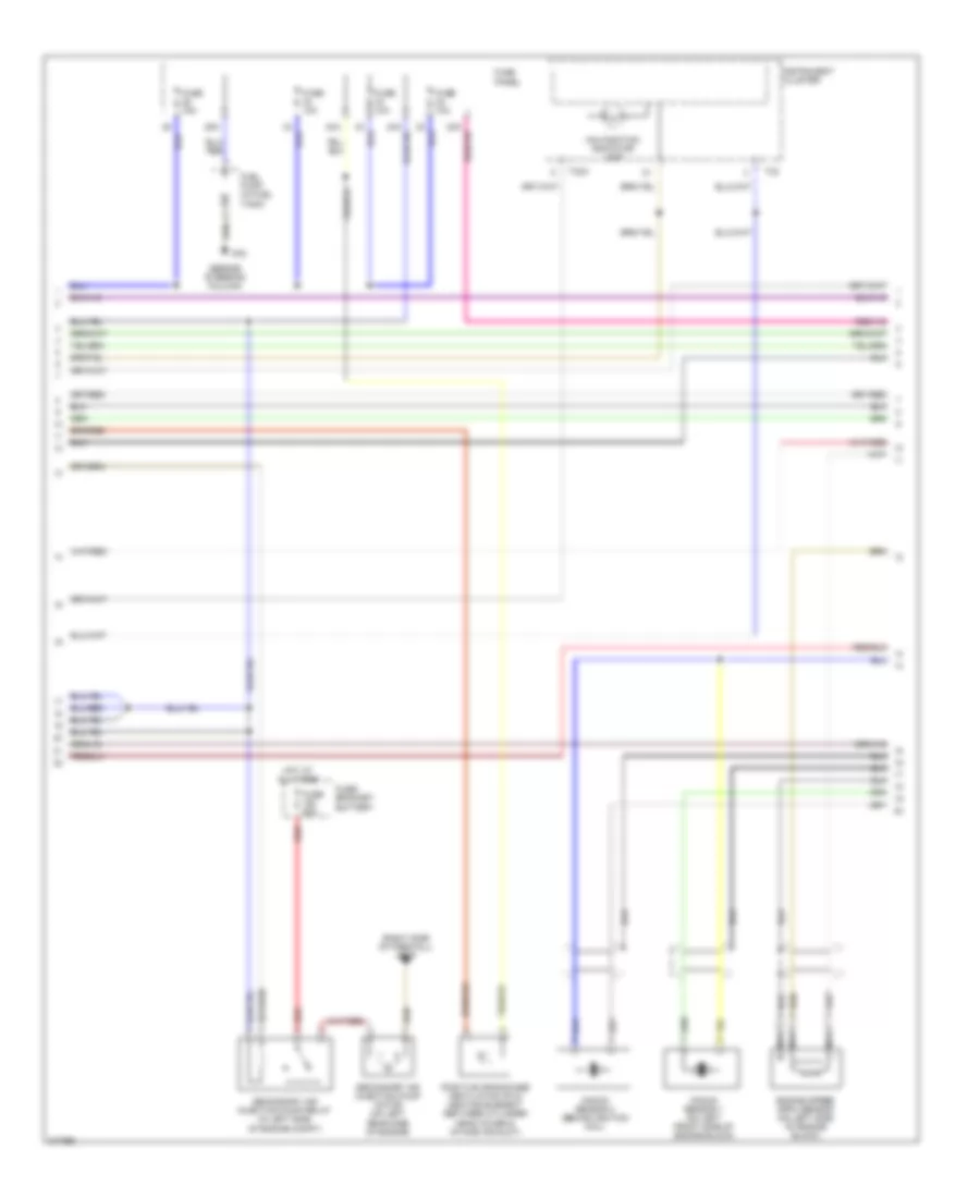
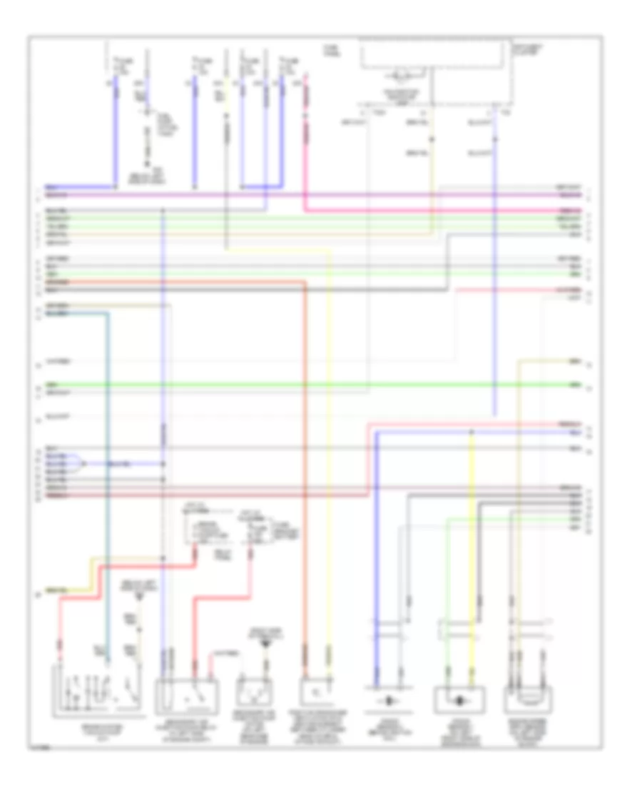
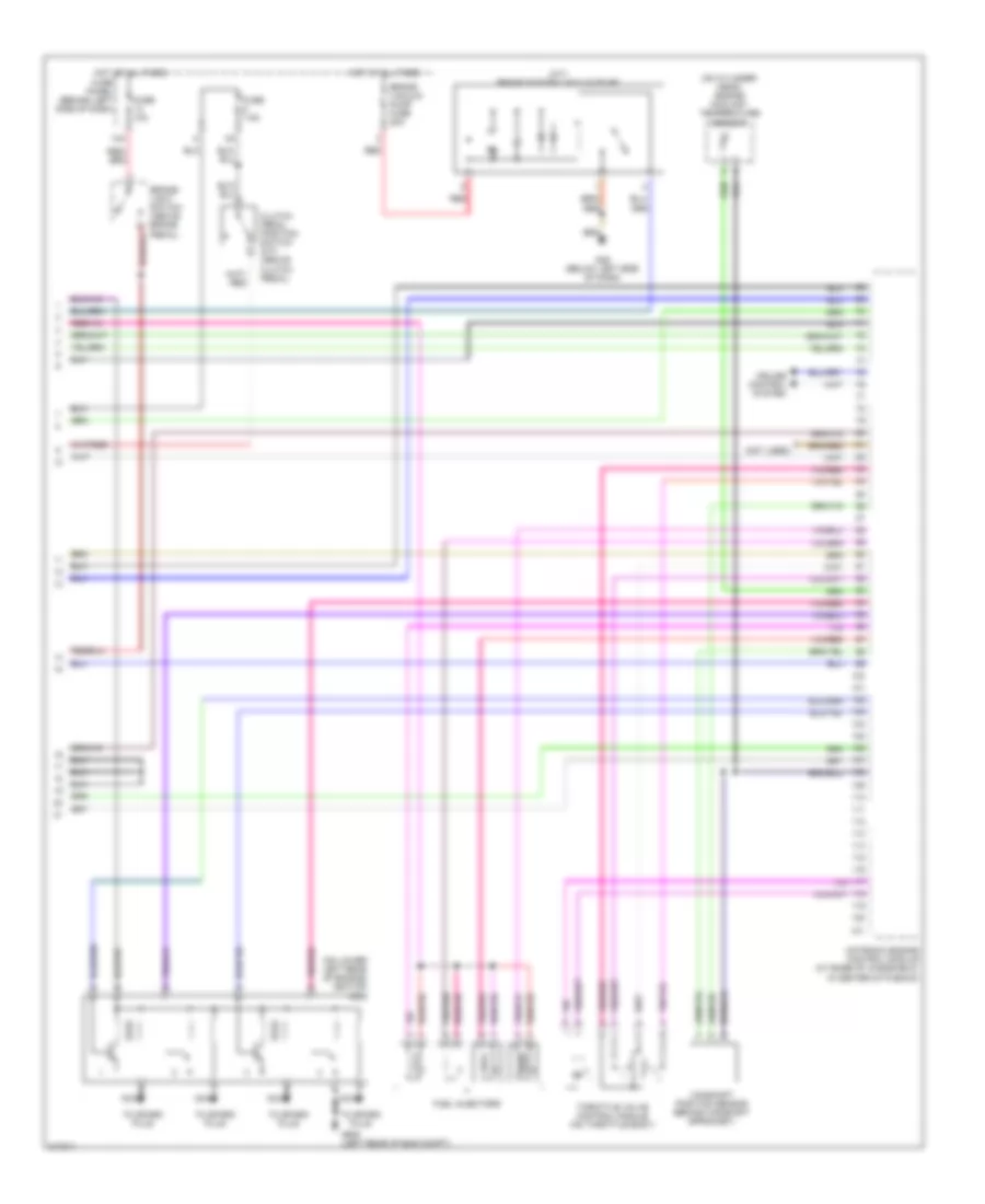
1.9L Turbo Diesel, Engine Performance Wiring Diagram (2 of 4) for Volkswagen Golf GL 2006
List of elements for 1.9L Turbo Diesel, Engine Performance Wiring Diagram (2 of 4) for Volkswagen Golf GL 2006:
- A/c system
- A/t
- Coolant glow plugs (m/t)
- Coolant preheating relay (high heat output) (m/t)
- Coolant preheating relay (low heat output) (m/t)
- Cruise control system
- Diesel direct fuel injection (dfi) engine control module (ecm) (base of wind- shield, center of plenum)
- Engine glow plugs
- Fuel pump
- Fuel pump relay
- Fuse 50a
- Fuse/ bracket battery (behind battery)
- G42 (below left side of dash)
- G608 (left rear of eng compt)
- Glow plug triggering control module
- Hot at all times
- M/t
- Red
- Starting/ charging system
- T94
- Transmission system
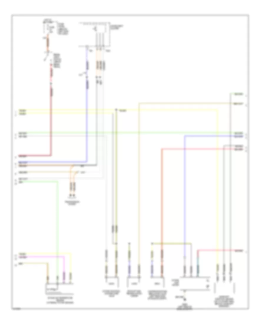
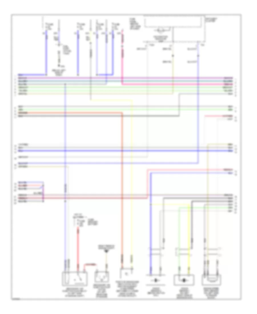
1.9L Turbo Diesel, Engine Performance Wiring Diagram (3 of 4) for Volkswagen Golf GL 2006
List of elements for 1.9L Turbo Diesel, Engine Performance Wiring Diagram (3 of 4) for Volkswagen Golf GL 2006:
- Brake- light switch (above brake pedal)
- Camshaft position sensor (on cylinder head, behind camshaft sprocket)
- Exhaust gas recirculation cooler
- Fuse 10a
- Fuse panel (behind left side of dash)
- G608 (left rear of engine compt)
- Hot at all times
- Instrument cluster
- Intake air temperature sensor (integral to map sensor)
- Intake flap motor
- Intake manifold change-over valve
- M/t
- Nca
- T32
- T32a
- Transmission system
- Wastegate bypass regulator valve (left rear side of engine compt)
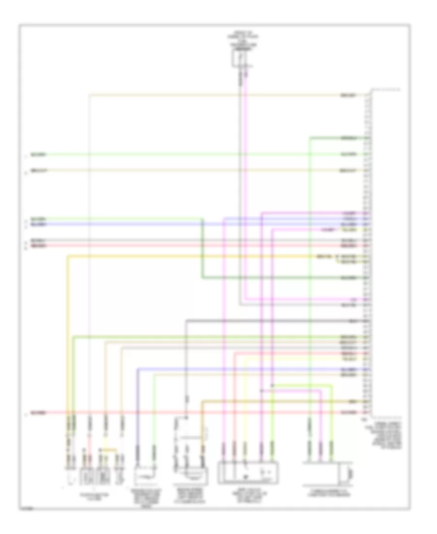
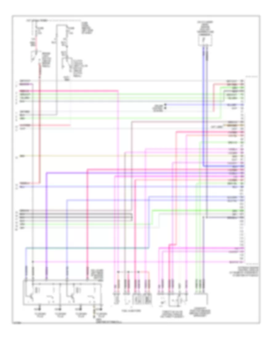
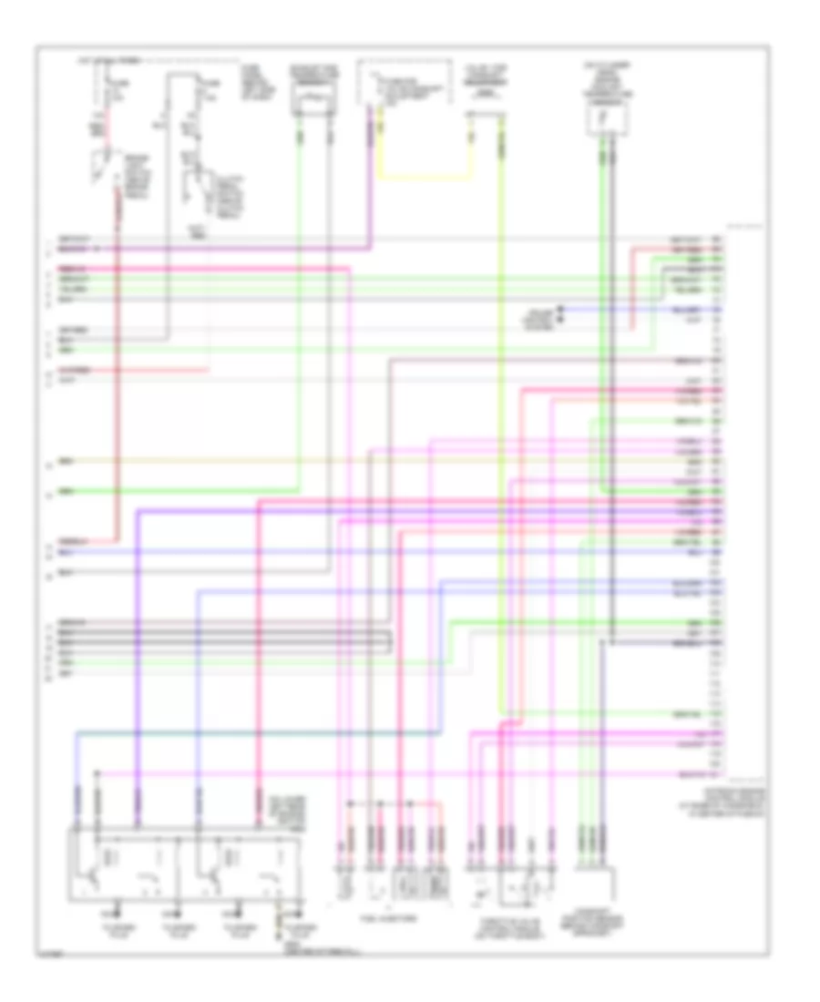
1.9L Turbo Diesel, Engine Performance Wiring Diagram (4 of 4) for Volkswagen Golf GL 2006
List of elements for 1.9L Turbo Diesel, Engine Performance Wiring Diagram (4 of 4) for Volkswagen Golf GL 2006:
- (front of diesel dfi pump) fuel temperature sensor
- Diesel direct fuel injection (dfi) engine control module (ecm) (base of wind- shield, center of plenum)
- Egr vacuum regulator valve (on left side of firewall)
- Engine coolant temperature (ect) sensor (on cylinder head)
- Engine speed (rpm) sensor (left rear of cylinder block)
- Nca
- Pump/injector valves
- Red
- T60
- Turbocharger (tc) vane position sensor
2.0L
2.0L, Engine Performance Wiring Diagram, Engine Code AVH (1 of 3) for Volkswagen Golf GL 2006
List of elements for 2.0L, Engine Performance Wiring Diagram, Engine Code AVH (1 of 3) for Volkswagen Golf GL 2006:
- (center of firewall) g608
- (not used)
- (pins 10-20 not used)
- (pins 22-24 not used)
- (pins 6-8 not used)
- A/c system
- Computer data lines system
- Cruise control system
- Evaporative emission canister purge regulator valve (next to engine coolant reservoir)
- Fuel pump relay
- Fuse 15a
- Fuse 20a
- Fuse 50a
- Fuse panel
- Fuse/ red bracket battery
- G42 (beside steering column)
- Heated oxygen sensor (ho2s) (ahead of three- way catalytic converter)
- Hot at all times
- Hot in run or start
- Ignition switch
- Leak detection pump (in right rear wheelhouse)
- Mass airflow (maf) sensor & intake air temperature (iat) sensor (in intake air duct)
- Motronic engine control module (at base of windshield, in center of plenum)
- Nca
- Oxygen sensor (o2s) (back of three- way catalytic converter)
- Red
- Relay panel
- Run
- Start
- Starting/ charging system
- Throttle position sensor/ accel pedal position sensor
2.0L, Engine Performance Wiring Diagram, Engine Code AVH (2 of 3) for Volkswagen Golf GL 2006
List of elements for 2.0L, Engine Performance Wiring Diagram, Engine Code AVH (2 of 3) for Volkswagen Golf GL 2006:
- (beside steering column)
- (right side of firewall) g609
- 28a
- 34a
- Engine speed (rpm) sensor (on left side of engine block)
- Fuel pump (in fuel tank)
- Fuse 10a
- Fuse 15a
- Fuse 50a
- Fuse panel
- Fuse/ bracket battery
- G42
- Hot at all times
- Instrument cluster
- Knock sensor 1 (on left front side of engine block)
- Knock sensor 2 (behind ignition coil)
- Malfunction indicator lamp
- Nca
- Positive crankcase ventilation (pvc) heating element (between cylinder head cover & intake air duct)
- Red
- Secondary air injection pump motor (on left rear side of engine)
- Secondary air injection pump relay (in left side of engine compt)
- T32
- T32a
2.0L, Engine Performance Wiring Diagram, Engine Code AVH (3 of 3) for Volkswagen Golf GL 2006
List of elements for 2.0L, Engine Performance Wiring Diagram, Engine Code AVH (3 of 3) for Volkswagen Golf GL 2006:
- (on cylinder head) engine coolant temperature sensor
- (on lower left rear of engine) ignition coil
- 13a
- Brake- light switch (above brake pedal)
- Camshaft position sensor (behind camshaft sprocket)
- Clutch vacuum vent valve switch (above clutch pedal)
- Cruise control system
- Fuel injectors
- Fuse 10a
- Fuse 7.5a
- Fuse panel (behind left side of dash)
- G608 (center of firewall)
- Hot at all times
- Motronic engine control module (at base of windshield, in center of plenum)
- Nca
- Not used
- Throttle valve control module (on throttle body)
- To spark plug
2.0L, Engine Performance Wiring Diagram, Engine Code BBW (1 of 3) for Volkswagen Golf GL 2006
List of elements for 2.0L, Engine Performance Wiring Diagram, Engine Code BBW (1 of 3) for Volkswagen Golf GL 2006:
- (center of firewall) g608
- (not used)
- (pins 12-15 not used)
- (pins 17-20 not used)
- (pins 7-9 not used)
- 29a
- 37a
- A/c system
- Computer data lines system
- Cruise control system
- Evaporative emission canister purge regulator valve (next to engine coolant reservoir)
- Fuel pump relay
- Fuse 15a
- Fuse 20a
- Fuse 50a
- Fuse panel
- Fuse/ red bracket battery
- G42 (below left side of dash)
- Heated oxygen sensor (ho2s) (ahead of three- way catalytic converter)
- Hot at all times
- Hot in run or start
- Ignition switch
- Leak detection pump (in right rear wheelhouse)
- Lock
- Mass airflow (maf) sensor & intake air temperature (iat) sensor (in intake air duct)
- Motronic engine control module (at base of windshield, in center of plenum)
- Nca
- Oxygen sensor (o2s) (back of three- way catalytic converter)
- Red
- Relay panel
- Run
- Start
- Starting/ charging system
- Throttle position sensor/ accel pedal position sensor
2.0L, Engine Performance Wiring Diagram, Engine Code BBW (2 of 3) for Volkswagen Golf GL 2006
List of elements for 2.0L, Engine Performance Wiring Diagram, Engine Code BBW (2 of 3) for Volkswagen Golf GL 2006:
- (a/t)
- (below left side of dash)
- (below left side of dash) g42
- (right side of firewall) g609
- 28a
- 34a
- Brake system vacuum pump
- Brake vacuum pump fuse 15a
- Engine speed (rpm) sensor (on left side of engine block)
- Fuel pump (in fuel tank)
- Fuse 10a
- Fuse 15a
- Fuse 50a
- Fuse panel
- Fuse/ bracket battery
- G42
- Hot at all times
- Instument cluster
- Knock sensor 1 (on left front side of engine block)
- Knock sensor 2 (behind ignition coil)
- Malfunction indicator lamp
- Nca
- Positive crankcase ventilation (pvc) heating element (between cylinder head cover & intake air duct)
- Red
- Relay panel
- Secondary air injection pump motor (on left rear side of engine)
- Secondary air injection pump relay (in left side of engine compt)
- T32
- T32a
2.0L, Engine Performance Wiring Diagram, Engine Code BBW (3 of 3) for Volkswagen Golf GL 2006
List of elements for 2.0L, Engine Performance Wiring Diagram, Engine Code BBW (3 of 3) for Volkswagen Golf GL 2006:
- (on cylinder head) engine coolant temperature sensor
- (on lower left rear of engine) ignition coil
- 13a
- Brake- light switch (above brake pedal)
- Camshaft position sensor (behind camshaft sprocket)
- Clutch pedal switch (above clutch pedal)
- Cruise control system
- Exhaust gas temperature sensor 1
- Fuel injectors
- Fuse 10a
- Fuse 7.5a
- Fuse for valve camshaft adjustment 10a
- Fuse panel (behind left side of dash)
- G608 (center of firewall)
- Hot at all times
- Motronic engine control module (at base of windshield, in center of plenum)
- Nca
- Throttle valve control module (on throttle body)
- To spark plug
- Valve 1 for camshaft adjustment
2.0L, Engine Performance Wiring Diagram, Engine Code BEV (1 of 3) for Volkswagen Golf GL 2006
List of elements for 2.0L, Engine Performance Wiring Diagram, Engine Code BEV (1 of 3) for Volkswagen Golf GL 2006:
- (left rear of engine compt) g608
- (not used)
- (pins 31, 32 not used)
- (pins 4,7-8,12-20,23 not used)
- A/c system
- All times
- Computer data lines system
- Cruise control system
- Evaporative emission canister purge regulator valve (next to engine coolant reservoir)
- Fuel pump relay
- Fuse 15a
- Fuse 20a
- Fuse 50a
- Fuse panel (behind left side of dash)
- G42 (below left side of dash)
- Heated oxygen sensor (ho2s) (ahead of three- way catalytic converter)
- Hot at
- Hot at all times
- Hot in run or start
- Ignition switch
- Leak detection pump (in right rear wheelwell)
- Lock
- Mass airflow (maf) sensor (in intake air duct)
- Motronic engine control module (at base of windshield, in center of plenum)
- Nca
- Oxygen sensor (o2s) (back of three- way catalytic converter)
- Red
- Red fuse/ bracket battery
- Relay panel
- Run
- Start
- Starting/ charging system
- Throttle position sensor/ accel pedal position sensor
2.0L, Engine Performance Wiring Diagram, Engine Code BEV (2 of 3) for Volkswagen Golf GL 2006
List of elements for 2.0L, Engine Performance Wiring Diagram, Engine Code BEV (2 of 3) for Volkswagen Golf GL 2006:
- (behind left side of dash)
- (below left side of dash)
- (right rear of engine compt) g609
- 28a
- 34a
- Engine speed (rpm) sensor (on left side of engine block)
- Fuel pump (in fuel tank)
- Fuse 10a
- Fuse 15a
- Fuse 50a
- Fuse panel
- Fuse/ bracket battery
- G42
- Hot at all times
- Instument cluster
- Knock sensor 1 (on left front side of engine block)
- Knock sensor 2 (behind ignition coil)
- Malfunction indicator lamp
- Nca
- Positive crankcase ventilation (pcv) heating element (if equipped) (between cylinder head cover & intake air duct)
- Red
- Secondary air injection pump motor (on left rear side of engine)
- Secondary air injection pump relay (in left side of engine compt)
- T32
- T32a
2.0L, Engine Performance Wiring Diagram, Engine Code BEV (3 of 3) for Volkswagen Golf GL 2006
List of elements for 2.0L, Engine Performance Wiring Diagram, Engine Code BEV (3 of 3) for Volkswagen Golf GL 2006:
- (a/t) brake system vacuum pump
- (not used)
- (on cylinder head) engine coolant temperature sensor
- (on lower left rear of engine) ignition coil
- 13a
- Brake vacuum pump fuse 20a
- Brake- light switch (above brake pedal)
- Camshaft position sensor (behind camshaft sprocket)
- Clutch pedal position switch (m/t) (above clutch pedal)
- Cruise control system
- Fuel injectors
- Fuse 10a
- Fuse 7.5a
- Fuse panel (behind left side of dash)
- G49 (below left side of dash)
- G608 (left rear of eng compt)
- Hot at all times
- Motronic engine control module (at base of windshield, in center of plenum)
- Nca
- Red
- Throttle valve control module (on throttle body)
- To spark plug