ENGINE PERFORMANCE
1.8L
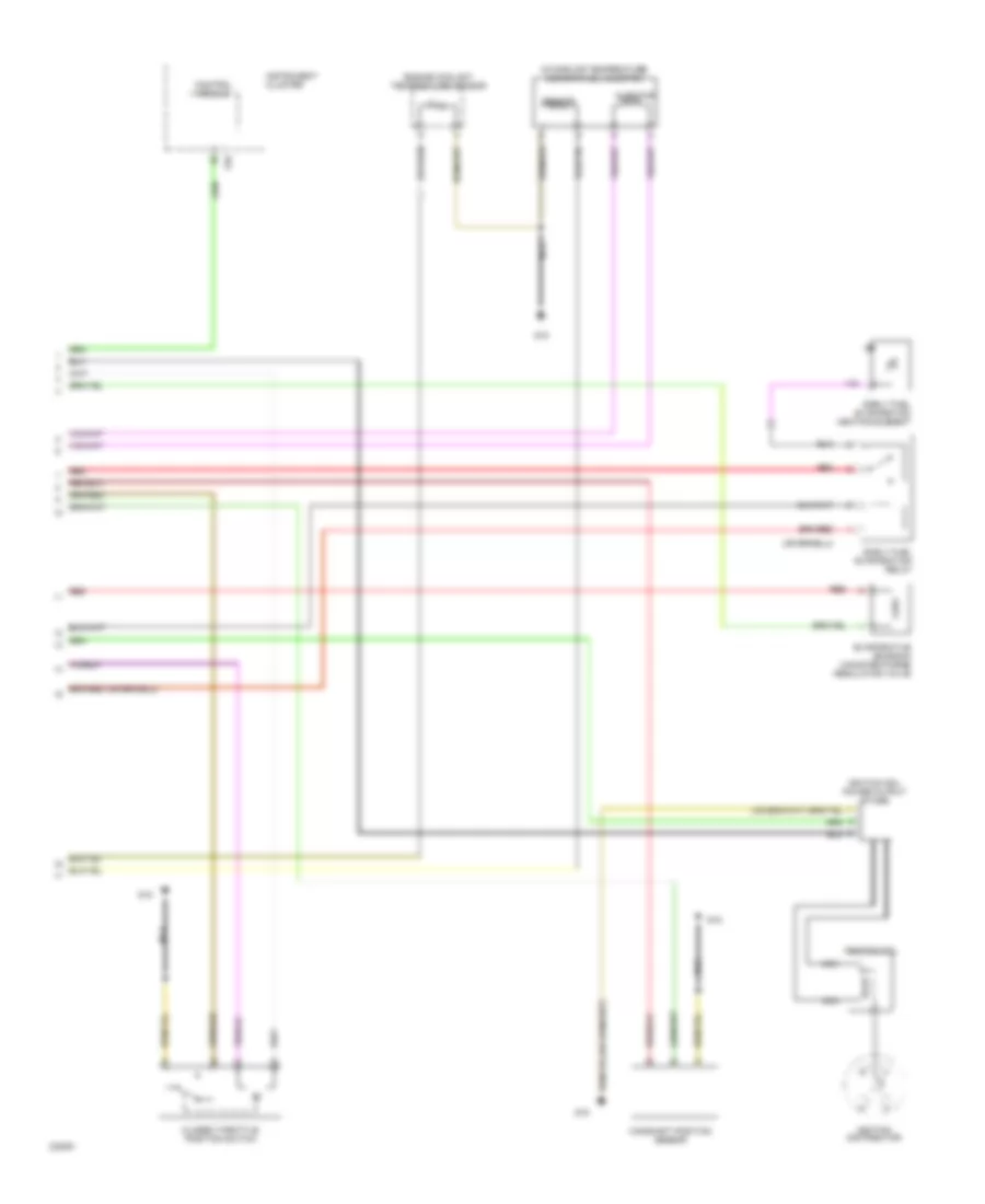
1.8L, Engine Performance Wiring Diagrams (1 of 2) for Volkswagen Golf III GL 1994

List of elements for 1.8L, Engine Performance Wiring Diagrams (1 of 2) for Volkswagen Golf III GL 1994:
- (not used)
- 1995-97
- 30b
- A/c system
- Battery
- Battery ground
- Diagnostic connector
- F/8
- Fuel pump
- Fuel pump relay
- Fuse 10a
- Fuse 20a
- Fuse/ relay panel
- G1/12
- G1/3
- G1/4
- G1/6
- G1/8
- G15
- G2/4
- G2/8
- G2/9
- Heated oxygen sensor (ho2s)
- Hot w/ load reduction relay energized
- Ignition
- J/c (tv2)
- Junction box for on board diagnostics
- M/1
- M/2
- Mono-motronic engine control module
- Nca
- Red
- T2a
- T2b
- Throttle position sensor
- U1/6
- Z/2
1.8L, Engine Performance Wiring Diagrams (2 of 2) for Volkswagen Golf III GL 1994
List of elements for 1.8L, Engine Performance Wiring Diagrams (2 of 2) for Volkswagen Golf III GL 1994:
- Camshaft position sensor
- Closed throttle position switch
- Control module
- Early fuel evaporation heating element
- Early fuel evaporation relay
- Engine coolant temperature sensor
- Evaporative emission canister purge regulator valve
- G15
- Ignition coil
- Ignition coil power output stage
- Ignition distributor
- Injector
- Instrument cluster
- Intake air temperature sensor/fuel injector
- Nca
- Red
- Sensor
- T28
1.9L
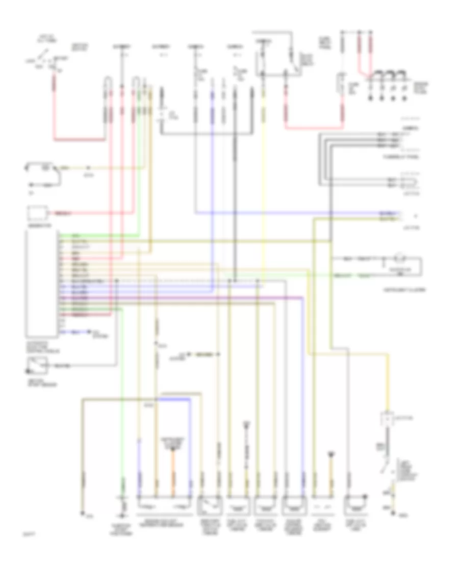
1.9L, Engine Performance Wiring Diagram for Volkswagen Golf III GL 1994
List of elements for 1.9L, Engine Performance Wiring Diagram for Volkswagen Golf III GL 1994:
- A/c system
- Acc
- Automatic glow time control module
- Battery
- D/11
- D/8
- E/2
- Egr part throttle switch (1995-96)
- Engine coolant temperature sensor
- Engine glow plugs
- F/5
- Fuel cut- off valve (1994)
- Fuel cut- off valve (1995-96)
- Fuse 10a
- Fuse 50a
- Fuse/ relay panel
- Fuse/relay panel
- G1/12
- G1/3
- G1/6
- G15
- G2/4
- G2/5
- G202
- G30
- G78
- Generator
- Glow plug ind
- Glow plug relay
- H1/1
- Hot at all times
- Idle air control solenoid (1995-96)
- Ignition
- Ignition start sensor
- Ignition switch
- Injection start positioner
- Instrument cluster
- Instrument cluster system
- J/c (tv15)
- J/c (tv2)
- J/c (tv4)
- J/c (tv5)
- Left front door contact switch
- Lock
- Nca
- Pcv heating element
- Red
- S119
- S131
- S132
- Start
- T28/13
- T28/20
- Two-way egr valve (1995-96)
- U1/8
- U2/1
- Y/1
- Z/1
2.0L
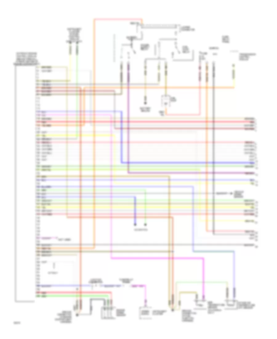
2.0L, Engine Performance Wiring Diagrams (1 of 2) for Volkswagen Golf III GL 1994
List of elements for 2.0L, Engine Performance Wiring Diagrams (1 of 2) for Volkswagen Golf III GL 1994:
- (behind firewall, in rear center of engine compartment)
- (not used)
- A/c switch
- A/t only
- Battery
- Battery ground
- Egr temperature sensor (california only)
- Engine speed sensor
- Fuel pump
- Fuel pump relay
- Fuse 20a
- Fuse/ relay panel
- Fuse/relay panel
- G1/3
- G1/4
- G1/7
- G1/8
- Gi/10
- Ground connection (in engine compartment harness)
- Ground connection (in fuel injection harness)
- Ignition
- Instrument cluster
- Instrument cluster system (control module/ display unit)
- Intake air temperature (iat) sensor
- Jumper connector
- Junction connector
- M/1
- M/2
- Motronic engine control module
- Red
- Speed signal
- Transmission control module
- U2/2
- Vehicle speed sensor
- W/1
- Z/2
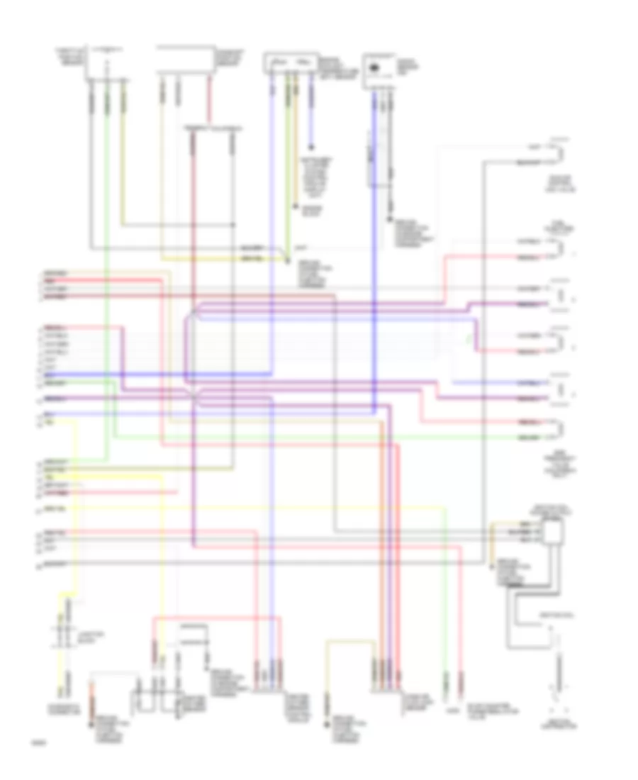
2.0L, Engine Performance Wiring Diagrams (2 of 2) for Volkswagen Golf III GL 1994
List of elements for 2.0L, Engine Performance Wiring Diagrams (2 of 2) for Volkswagen Golf III GL 1994:
- California
- Camshaft position sensor
- Diagnostic connector
- Egr frequency valve (california only)
- Engine block
- Engine coolant temperature (ect) sensor
- Evap canister purge regulator valve
- Federal
- Fuel injectors
- Ground connection (in engine compartment harness)
- Ground connection (in fuel injection harness)
- Heated oxygen sensor
- Heated oxygen sensor control module
- Idle air control (iac) valve
- Ignition coil
- Ignition coil power output stage
- Ignition distributor
- Instrument cluster system (control module/ display unit)
- Junction block
- Knock sensor (ks)
- Mass air flow (maf) sensor
- Nca
- Red
- Throttle position sensor