ENGINE PERFORMANCE
2.0L
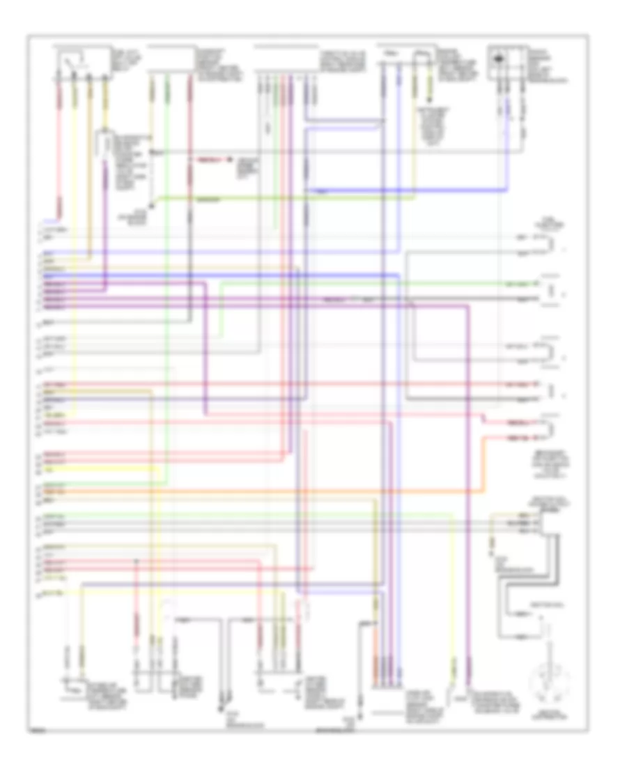
2.0L, Engine Performance Wiring Diagrams (1 of 2) for Volkswagen GTI 1997

List of elements for 2.0L, Engine Performance Wiring Diagrams (1 of 2) for Volkswagen GTI 1997:
- (in engine compartment, on center of plenum)
- 30b
- A/c clutch cut-off relay
- Battery
- Battery ground
- Calif only
- D/8
- Data link connector (center of dash)
- E/2
- Engine speed sensor (front center of engine compt)
- Fuel pump
- Fuel pump relay
- Fuse 10a
- Fuse 20a
- Fuse 30a
- Fuse/ relay panel
- Fuse/relay panel
- G1/3
- G1/4
- G1/6
- G1/8
- G1/9
- G132 (on engine block)
- G2/4
- G2/8
- G2/9
- Ignition
- Instrument cluster
- Instrument cluster system (control module/ display unit)
- Junction block (above fuse/ relay panel)
- Junction connector
- Leak detection pump
- M/1
- M/2
- Malfunction indicator lamp
- Motronic engine control module
- Nca
- Red
- Right seat belt control unit
- Secondary air injection (air) pump motor
- Secondary air injection (air) pump relay
- T28-13
- T28-20
- Transmission control module
- U1/9
- U2/1
- U2/2
- Vehicle speed sensor (m/t)
- Vehicle speed signal
- W/1
- Z/2
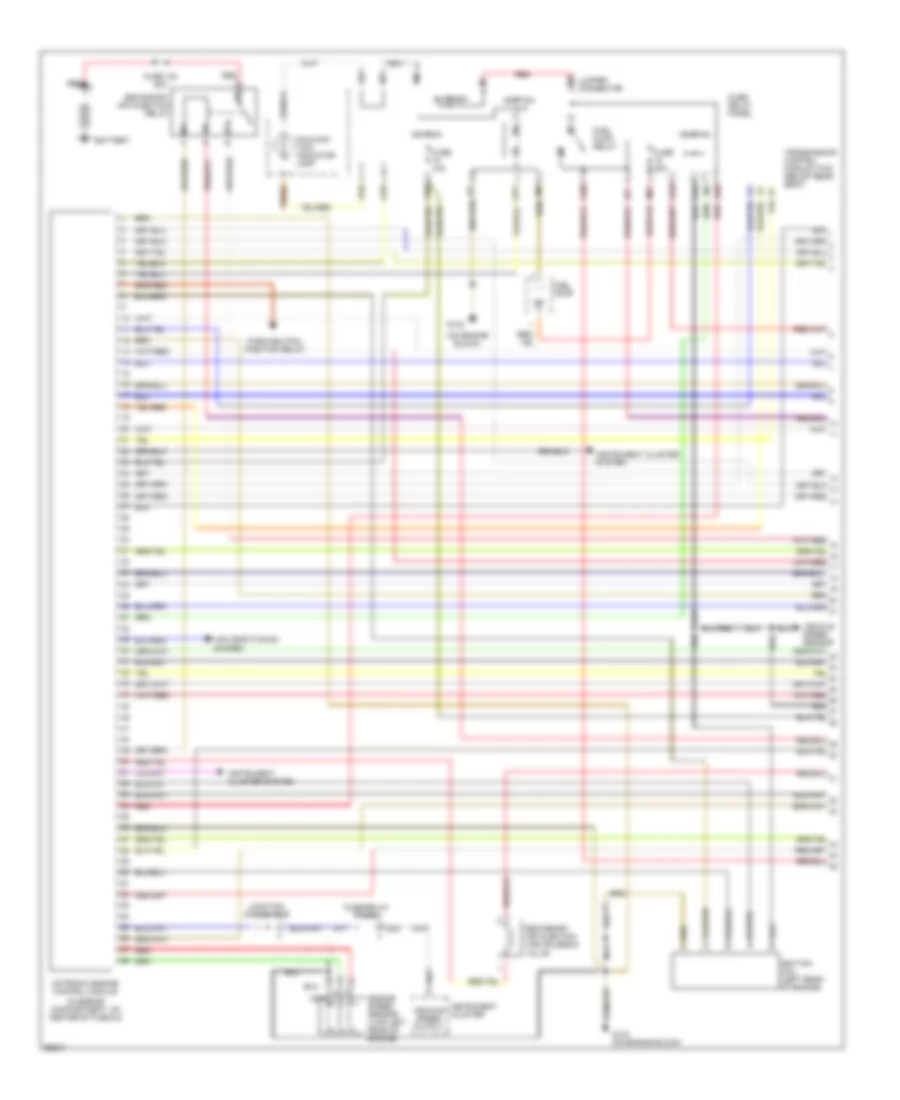
2.0L, Engine Performance Wiring Diagrams (2 of 2) for Volkswagen GTI 1997
List of elements for 2.0L, Engine Performance Wiring Diagrams (2 of 2) for Volkswagen GTI 1997:
- Blu
- Camshaft position sensor (front center of engine compt, on distributor)
- Engine coolant temperature (ect) sensor (front center of eng compt)
- Evaporative emission (evap) canister purge regulator valve (right side of eng compt)
- Evaporative emission (evap) canister purge solenoid valve
- Fuel cut- off valve/ shut off relay
- Fuel injectors
- G132 (on engine block)
- Heated oxygen sensor (ho2s)
- Heated oxygen sensor (ho2s) 2 (right rear of engine compt)
- Ignition coil
- Ignition coil power output stage
- Ignition distributor
- Instrument cluster system (control module/ display unit)
- Intake air temperature (iat) sensor (right center of eng compt)
- Knock sensor (ks) (on left side of engine block)
- Mass air flow (maf) sensor (right side of engine compt, on air duct)
- Nca
- Secondary air injection (air) solenoid valve (calif only)
- Throttle valve control module (right rear side of engine compt)
- Vehicle speed sensor (a/t)
2.8L
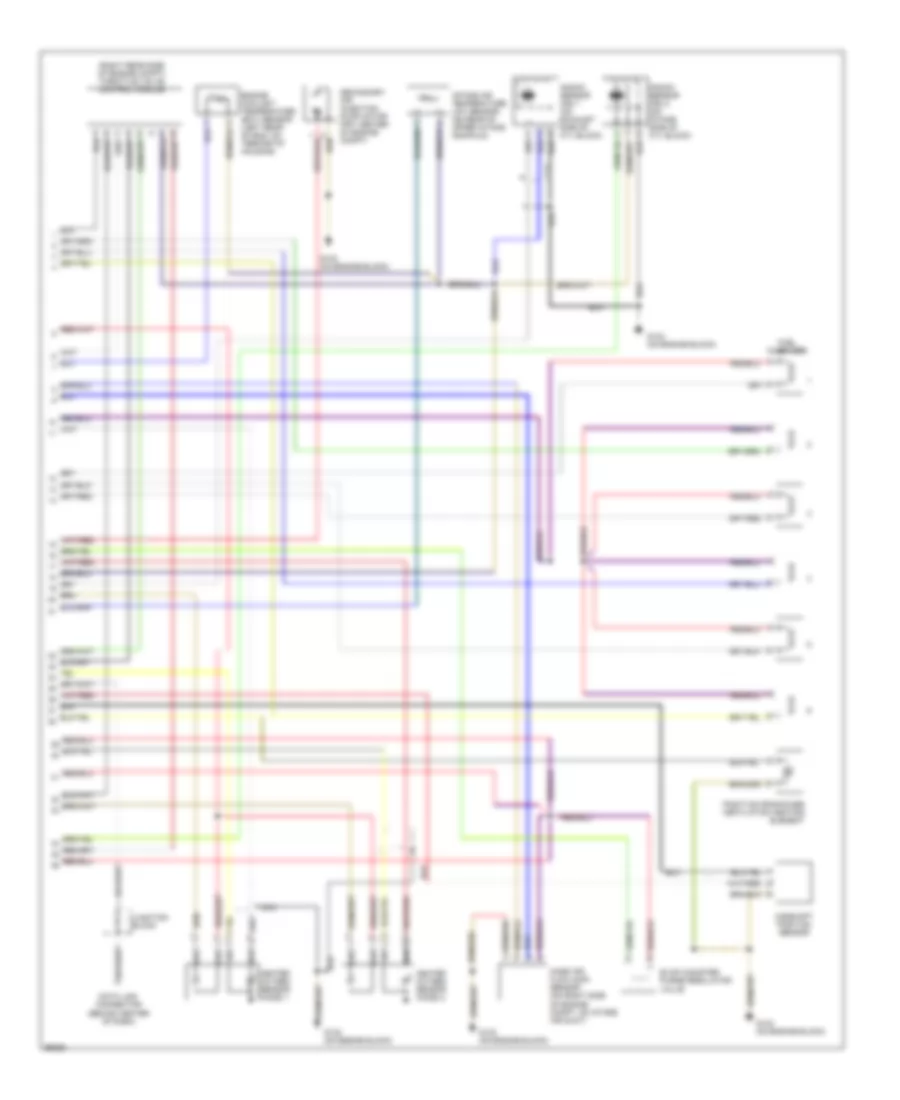
2.8L, Engine Performance Wiring Diagrams (1 of 2) for Volkswagen GTI 1997
List of elements for 2.8L, Engine Performance Wiring Diagrams (1 of 2) for Volkswagen GTI 1997:
- (in engine compartment, on center of plenum)
- (on engine block)
- 30b
- Air conditioning system
- Battery
- D/8
- E/2
- Engine speed sensor (lwr left rear of engine)
- Fuel pump
- Fuel pump relay
- Fuse 10a
- Fuse 130 50a
- Fuse 20a
- Fuse/ relay panel
- Fuse/relay panel
- G1/3
- G1/4
- G1/8
- G1/9
- G132
- G132 (on engine block)
- G2/4
- G2/8
- G2/9
- Ignition
- Ignition coil (left rear of engine)
- Instrument cluster
- Instrument cluster system
- Jumper connector
- Junction connector
- M/1
- M/2
- Malfunc- tion indicator lamp
- Motronic engine control module
- N/1
- Nca
- Park/neutral position relay
- Red
- Secondary air injection (air) solenoid valve
- Secondary air injection relay
- T28/13
- T28/20
- Transmission control module (tcm) (below rear seat)
- U1/9
- U2/1
- U2/2
- Vehicle speed output
- Vehicle speed sensor
- W/1
- Z/1
- Z/2
2.8L, Engine Performance Wiring Diagrams (2 of 2) for Volkswagen GTI 1997
List of elements for 2.8L, Engine Performance Wiring Diagrams (2 of 2) for Volkswagen GTI 1997:
- (right rear side of engine compt) throttle valve control module
- Camshaft position sensor
- Data link connector (behind center of dash)
- Engine coolant temperature (ect) sensor (left rear of eng, on termostat housing)
- Evap canister purge regulator valve
- Fuel injectors
- G132 (on engine block)
- Heated oxygen sensor (ho2s) 1
- Heated oxygen sensor (ho2s) 2
- Intake air temperature (iat) sensor (on rear of upper intake manifold)
- Junction block
- Knock sensor (ks) 1 (on exhaust side of cyl block)
- Knock sensor (ks) 2 (on intake side of cyl block)
- Mass air flow (maf) sensor (on right side of engine compt, on intake air duct)
- Nca
- Positive crankcase ventilation heating element
- Secondary air injection pump motor (frt center of engine compt)