ENGINE PERFORMANCE
1.8L
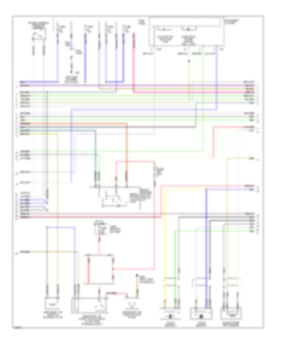
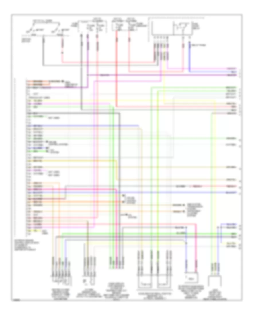
1.8L Turbo, Engine Performance Wiring Diagrams (1 of 3) for Volkswagen GTI 2002

List of elements for 1.8L Turbo, Engine Performance Wiring Diagrams (1 of 3) for Volkswagen GTI 2002:
- (a/t)
- (not used)
- (pins 10-20 not used)
- (pins 23, 24 & 26 not used)
- (pins 6-8 not used)
- 10a
- 29a
- 31a
- A/c system
- Accelerator pedal position sensors 1 & 2 (in the pedal assembly)
- Computer data lines system
- Cruise control system
- Early production or late production w/ m/t
- Evaporative emission canister purge regulator valve
- Fuel pump relay
- Fuse 15a
- Fuse 20a
- Fuse 50a
- Fuse panel
- Fuse/ red bracket battery
- G42 (left side of steer- ing column)
- G608 (left side of firewall)
- Heated oxygen sensor (ho2s)
- Hot at all times
- Hot in run or start
- Ignition switch
- Late production w/ a/t
- Leak detection pump
- Lock
- Mass airflow sensor
- Motronic engine control module (in protective box, in left rear corner of engine compartment)
- Nca
- Oxygen sensor (o2s) (behind catalytic converter)
- Red
- Relay panel
- Run
- Start
- Starting/ charging system
- Transmission system
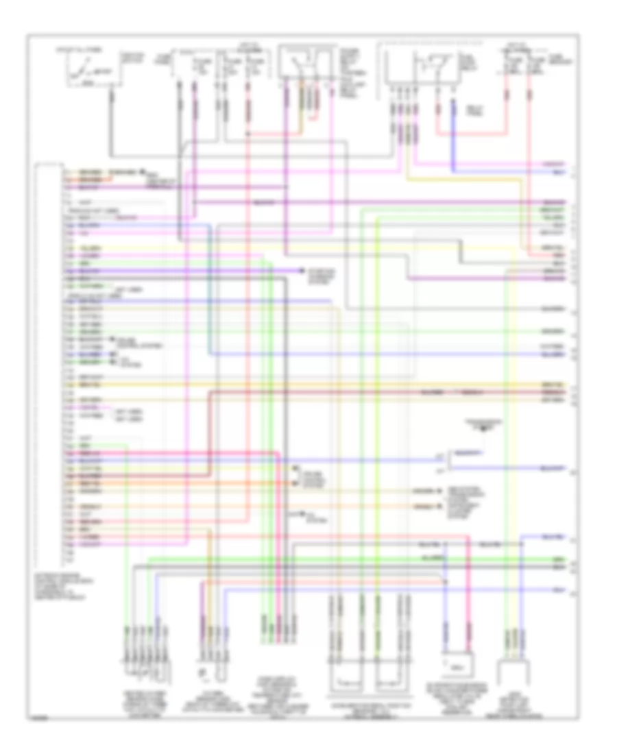
1.8L Turbo, Engine Performance Wiring Diagrams (2 of 3) for Volkswagen GTI 2002
List of elements for 1.8L Turbo, Engine Performance Wiring Diagrams (2 of 3) for Volkswagen GTI 2002:
- (left side of steer- ing column)
- 28a
- A/t
- Brake booster control module (a/t)
- Brake system vacuum pump
- Electronic power control fault light
- Engine speed (rpm) sensor
- Fuel pump
- Fuse 10a
- Fuse 15a
- Fuse 50a
- Fuse panel
- Fuse s51 20a
- Fuse/ bracket battery
- G42
- G609 (right side of firewall)
- Hot at all times
- Instrument cluster
- Knock sensor 1
- Knock sensor 2
- M/t
- Malfunction indicator lamp
- Nca
- Power steering pressure switch
- Red
- Secondary air injection pump motor
- Secondary air injection pump relay (in left side of engine compt)
- Secondary air injection solenoid valve
- T32
- T32a
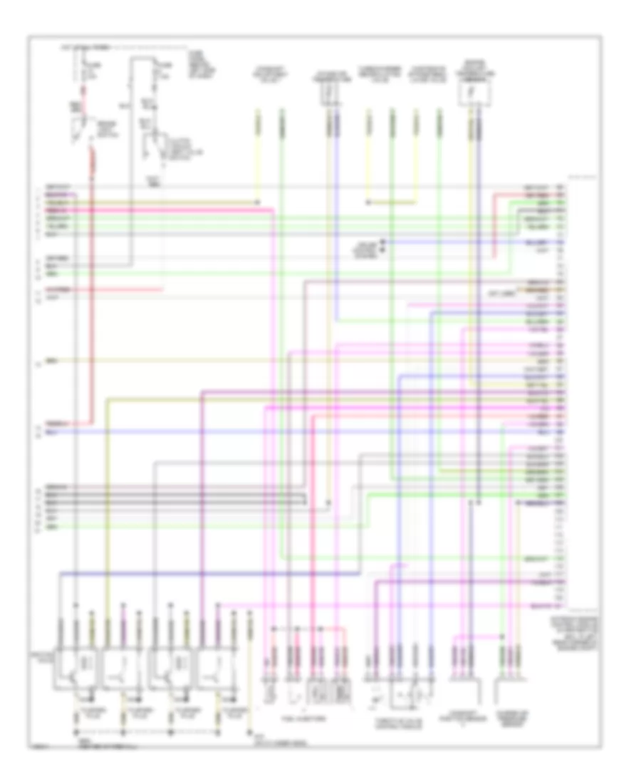
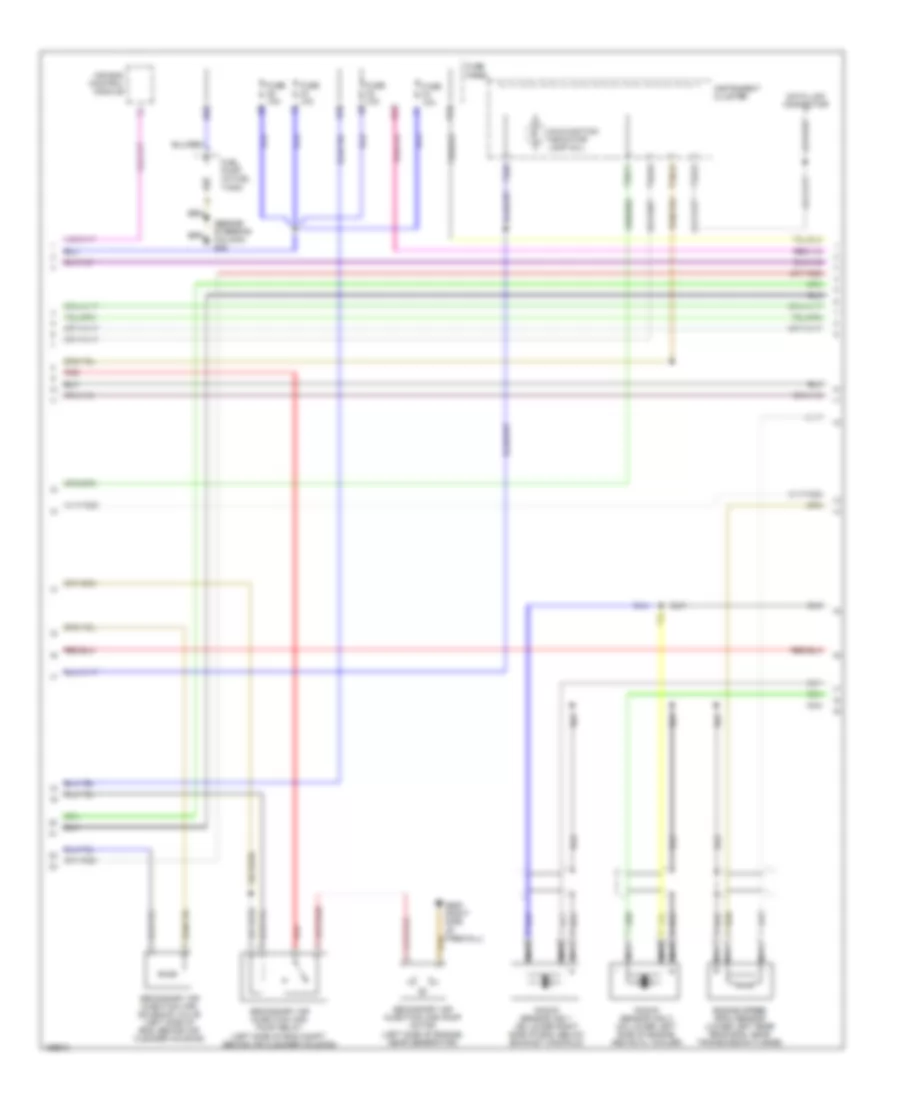
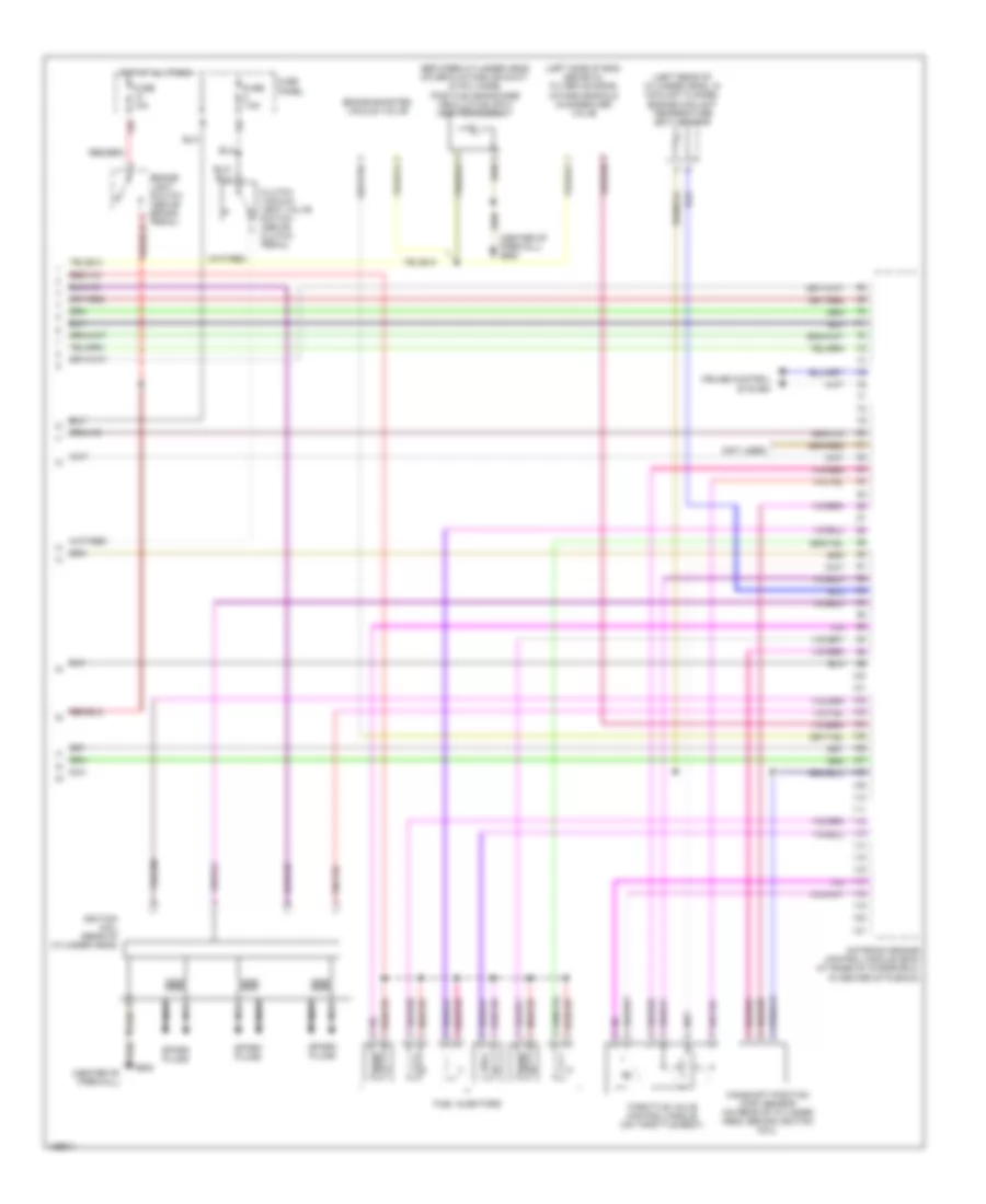
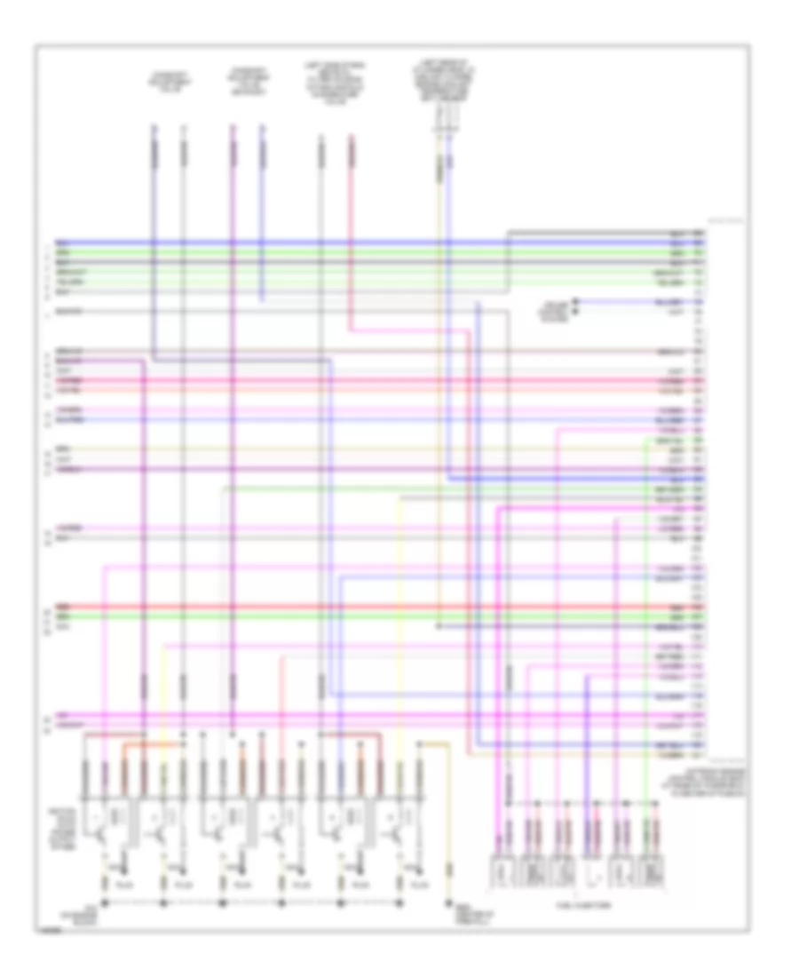
1.8L Turbo, Engine Performance Wiring Diagrams (3 of 3) for Volkswagen GTI 2002
List of elements for 1.8L Turbo, Engine Performance Wiring Diagrams (3 of 3) for Volkswagen GTI 2002:
- 13a
- Brake- light switch
- Camshaft adjustment valve 1
- Camshaft position sensor
- Charge air pressure sensor
- Clutch vacuum vent valve switch
- Cruise control system
- Engine coolant temperature sensor
- Fuel injectors
- Fuse 10a
- Fuse 7.5a
- Fuse panel (behind left side of dash)
- G15 (on cylinder head)
- G608 (center of firewall)
- Hot at all times
- Ignition coils
- Intake air temperature
- Motronic engine control module (in protective box, in left rear corner of engine compt)
- Nca
- Not used
- Throttle valve control module
- To spark plug
- Turbocharger recirculating valve
- Wastegate bypass regu- lator valve
2.8L
2.8L, Engine Performance Wiring Diagrams, Early Production (1 of 3) for Volkswagen GTI 2002
List of elements for 2.8L, Engine Performance Wiring Diagrams, Early Production (1 of 3) for Volkswagen GTI 2002:
- (not used)
- (pins 6-24 not used)
- 10a
- 29a
- A/c system
- Abs system, transmission system, instrument cluster system
- Accelerator pedal position sensors 1 & 2 (in pedal assembly)
- Cruise control system
- Evaporative emission (evap) canister purge regulator valve (next to eng coolant reservoir)
- Fuel pump relay
- Fuse 15a
- Fuse 50a
- Fuse bracket
- Fuse panel
- G608 (center of firewall)
- Heated oxygen sensor (ho2s) (ahead of three way catalytic converter)
- Hot at all times
- Ignition switch
- Leak detection pump (ldp) (inside right rear wheelhousing)
- Mass airflow (maf) sensor & intake air temperature (iat) sensor (between air cleaner housing & throttle body)
- Motronic engine control module (ecm) (at base of windshield, in center of plenum)
- Nca
- Off
- Oxygen sensor (o2s) (back of three-way catalytic converter)
- Red
- Relay panel
- Run
- S3/1
- S3/2
- S3/3
- S3/5
- S3/6
- Start
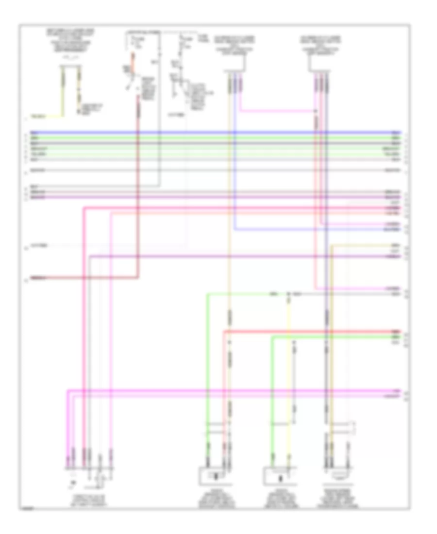
2.8L, Engine Performance Wiring Diagrams, Early Production (2 of 3) for Volkswagen GTI 2002
List of elements for 2.8L, Engine Performance Wiring Diagrams, Early Production (2 of 3) for Volkswagen GTI 2002:
- (beside steering column) g42
- (mil)
- 28a
- 32a
- 34a
- 43a
- Air bag control module
- Data link connector
- Engine speed (rpm) sensor (lower left rear rear eng, near transmission flange)
- Fuel pump (in fuel tank)
- Fuse 10a
- Fuse panel
- G609 (right side of firewall)
- Instrument cluster
- Knock sensor (ks) 1 (on lower right side of eng, below exhaust manifold)
- Knock sensor (ks) 2 (on lower left side of engine, above oil cooler)
- Malfunction indicator lamp
- Nca
- Red
- Secondary air injection (air) pump motor (left side of engine, near generator)
- Secondary air injection (air) pump relay (left side of eng compt, behind air cleaner housing)
- Secondary air injection (air) solenoid valve (left side of eng, behind air cleaner housing)
- T32/11
- T32/21
- T32/25
- T32/3
- T32a/5
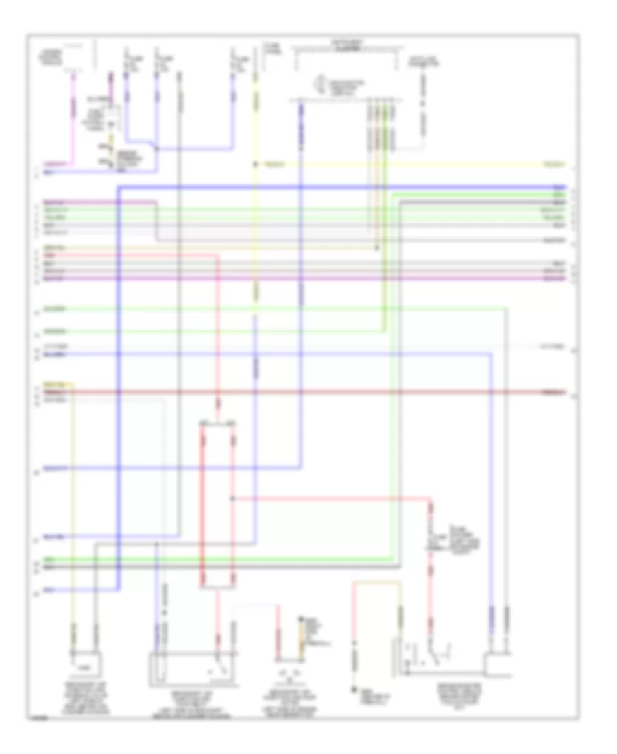
2.8L, Engine Performance Wiring Diagrams, Early Production (3 of 3) for Volkswagen GTI 2002
List of elements for 2.8L, Engine Performance Wiring Diagrams, Early Production (3 of 3) for Volkswagen GTI 2002:
- (between cylinder head cover & intake air duct, in pcv hose) positive crankcase ventilation (pcv) heating element
- (center of firewall)
- (center of firewall) g608
- (left rear of cylinder head, in coolant flange) engine coolant temperature (ect) sensor
- (left side of eng, above oil filter housing)
- (not used)
- 13a
- Brake booster vacuum valve
- Brake- light switch (above brake pedal)
- Camshaft position (cmp) sensor (on rear of cylinder head, behind ignition coil)
- Clutch vacuum vent valve switch (above clutch pedal)
- Cruise control system
- Fuel injectors
- Fuse 10a
- Fuse 7.5a
- Fuse panel
- G608
- Hot at all times
- Ignition coil (rear of cylinder head)
- Intake manifold change-over valve
- Motronic engine control module (ecm) (at base of windshield, in center of plenum)
- Nca
- Spark plugs
- Throttle valve control module (on throttle body)
2.8L, Engine Performance Wiring Diagrams, Late Production (1 of 4) for Volkswagen GTI 2002
List of elements for 2.8L, Engine Performance Wiring Diagrams, Late Production (1 of 4) for Volkswagen GTI 2002:
- (not used)
- (pins 31-32 not used)
- (pins 6-20 not used)
- 10a
- 29a
- 31a
- A/c system
- A/t
- Abs system, transmission system, instrument cluster system
- Accelerator pedal position sensors 1 & 2 (in pedal assembly)
- Cruise control system
- Evaporative emission (evap) canister purge regulator valve (next to eng coolant reservoir)
- Fuel pump relay
- Fuse 15a
- Fuse 20a
- Fuse 50a
- Fuse bracket
- Fuse panel
- G608 (center of firewall)
- Heated oxygen sensor (ho2s) (ahead of three way catalytic converter)
- Hot at all times
- Ignition switch
- Leak detection pump (ldp) (inside right rear wheelhousing)
- M/t
- Mass airflow (maf) sensor & intake air temperature (iat) sensor (between air cleaner housing & throttle body)
- Motronic engine control module (ecm) (at base of windshield, in center of plenum)
- Nca
- Off
- Oxygen sensor (o2s) (back of three-way catalytic converter)
- Red
- Relay panel
- Run
- S3/1
- S3/3
- S3/5
- S3/6
- Start
- Starting/ charging system
- Transmission system
2.8L, Engine Performance Wiring Diagrams, Late Production (2 of 4) for Volkswagen GTI 2002
List of elements for 2.8L, Engine Performance Wiring Diagrams, Late Production (2 of 4) for Volkswagen GTI 2002:
- (beside steering column) g42
- (mil)
- 28a
- 34a
- 43a
- A/t
- Air bag control module
- Brake booster control module (brake system vacuum pump) (a/t)
- Data link connector
- Fuel pump (in fuel tank)
- Fuse 10a
- Fuse 20a
- Fuse holder (left side of engine compt)
- Fuse panel
- G608 (center of firewall)
- G609 (right side of firewall)
- Instrument cluster
- M/t
- Malfunction indicator lamp
- Red
- Secondary air injection (air) pump motor (left side of engine, near generator)
- Secondary air injection (air) pump relay (left side of eng compt, behind air cleaner housing)
- Secondary air injection (air) solenoid valve (left side of eng, behind air cleaner housing)
- T32/11
- T32/21
- T32/25
- T32/3
- T32a/5
2.8L, Engine Performance Wiring Diagrams, Late Production (3 of 4) for Volkswagen GTI 2002
List of elements for 2.8L, Engine Performance Wiring Diagrams, Late Production (3 of 4) for Volkswagen GTI 2002:
- (between cylinder head cover & intake air duct, in pcv hose) positive crankcase ventilation (pcv) heating element
- (center of firewall) g608
- (on rear of cylinder head, behind ignition coil) camshaft position (cmp) sensor
- (on rear of cylinder head, behind ignition coil) camshaft position (cmp) sensor 2
- 13a
- Brake- light switch (above brake pedal)
- Clutch vacuum vent valve switch (above clutch pedal)
- Engine speed (rpm) sensor (lower left rear rear eng, near transmission flange)
- Fuse 10a
- Fuse 7.5a
- Fuse panel
- Hot at all times
- Knock sensor (ks) 1 (on lower right side of eng, below exhaust manifold)
- Knock sensor (ks) 2 (on lower left side of engine, above oil cooler)
- Nca
- Red
- Throttle valve control module (on throttle body)
2.8L, Engine Performance Wiring Diagrams, Late Production (4 of 4) for Volkswagen GTI 2002
List of elements for 2.8L, Engine Performance Wiring Diagrams, Late Production (4 of 4) for Volkswagen GTI 2002:
- (left rear of cylinder head, in coolant flange) engine coolant temperature (ect) sensor
- (left side of eng, above oil filter housing)
- Camshaft adjustment valve
- Camshaft adjustment valve (exhaust)
- Cruise control system
- Fuel injectors
- G18 (on engine block)
- G608 (center of firewall)
- Ignition coils (with power output stage)
- Intake manifold change-over valve
- Motronic engine control module (ecm) (at base of windshield, in center of plenum)
- Nca
- Plug
- Red