ENGINE PERFORMANCE
2.8L
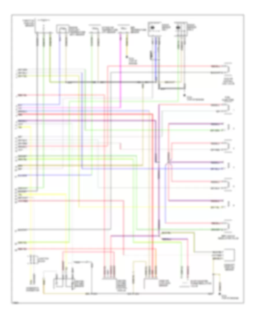
2.8L, Engine Performance Wiring Diagrams (1 of 2) for Volkswagen GTI VR6 1995

List of elements for 2.8L, Engine Performance Wiring Diagrams (1 of 2) for Volkswagen GTI VR6 1995:
- (behind firewall, in rear center of engine compartment)
- A/c system
- A/t control module
- A/t only
- Battery
- Battery ground
- Ecm power relay
- Engine speed sensor
- Fuel pump
- Fuel pump relay
- Fuse 20a
- Fuse 30a
- Fuse/ relay panel
- Fuse/relay panel
- G1/10
- G1/3
- G1/4
- G1/7
- G1/8
- G134 (top of engine)
- G2/8
- Ignition
- Ignition coil
- Instrument cluster
- Instrument cluster system (pin 10)
- Jumper connector
- Junction connector
- M/1
- M/2
- Motronic engine control module
- Nca
- Red
- Secondary air injection pump motor
- Secondary air injection relay
- Secondary air injection solenoid valve
- U2/2
- Vehicle speed output
- Vehicle speed sensor
- W/1
- Warning indicator module (mil)
- Z/2
2.8L, Engine Performance Wiring Diagrams (2 of 2) for Volkswagen GTI VR6 1995
List of elements for 2.8L, Engine Performance Wiring Diagrams (2 of 2) for Volkswagen GTI VR6 1995:
- Camshaft position sensor
- Diagnostic connector
- Egr temperature sensor
- Egr vacuum regulator valve
- Engine coolant temperature (ect) sensor
- Evap canister purge regulator valve
- Fuel injectors
- G134 (top of engine)
- Heated oxygen sensor
- Heated oxygen sensor control module
- Idle air control (iac) valve
- Intake air temperature (iat) sensor
- Junction block
- Knock sensor (ks) 1
- Knock sensor (ks) 2
- Mass air flow (maf) sensor
- Nca
- Red
- Throttle position sensor