ENGINE PERFORMANCE
2.3L
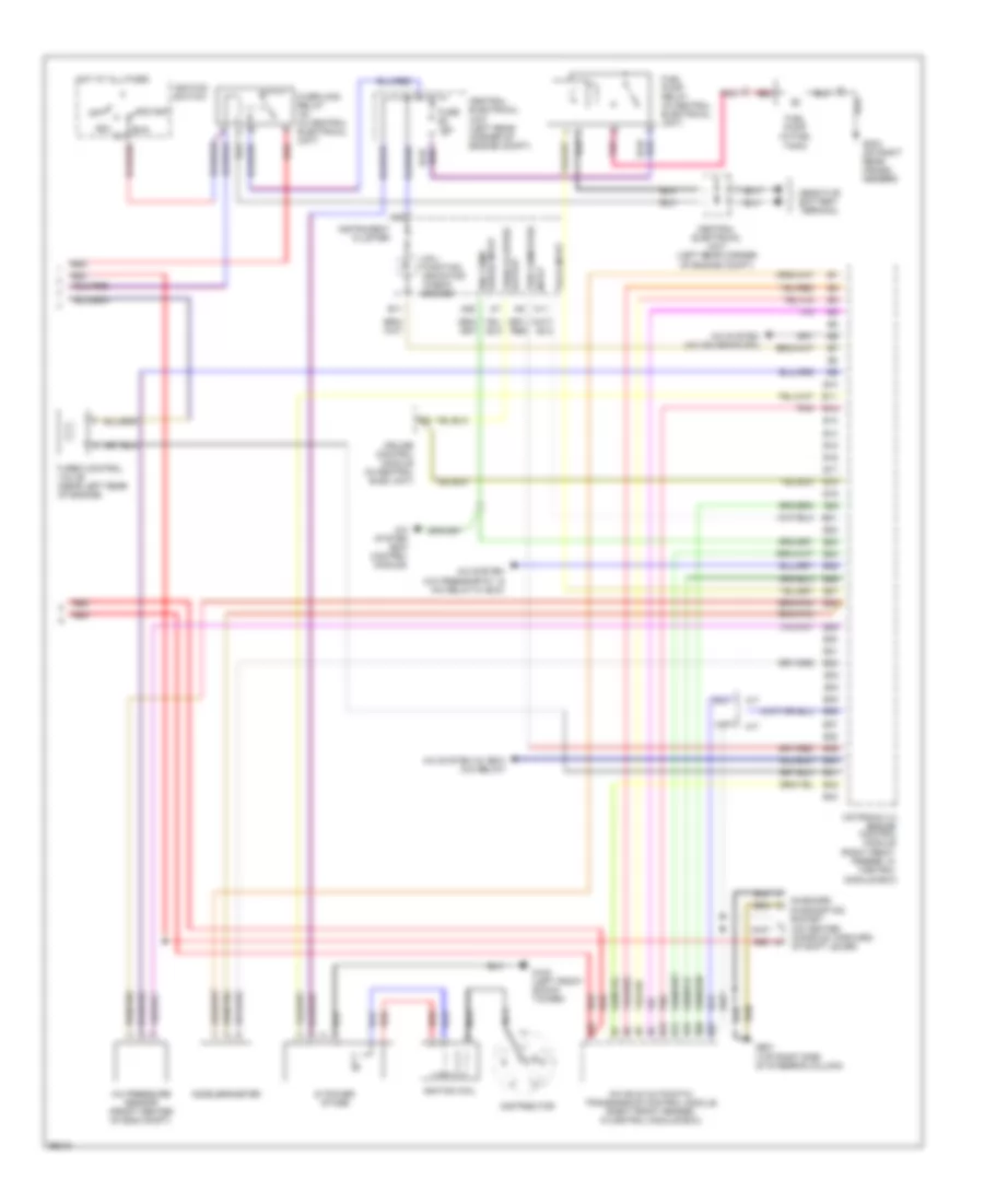
2.3L Turbo, Engine Performance Wiring Diagrams (1 of 2) for Volvo 850 GLT 1997

List of elements for 2.3L Turbo, Engine Performance Wiring Diagrams (1 of 2) for Volvo 850 GLT 1997:
- (a/t)
- (left front of eng compt) evap valve
- (m/t)
- (rear) (lower front of eng block)
- A/t
- A10
- A11
- A12
- A13
- A14
- A15
- A16
- A17
- A18
- A19
- A20
- A21
- A22
- A23
- A24
- A25
- A26
- A27
- A28
- A29
- A30
- A31
- A32
- A33
- A34
- A35
- A36
- A37
- A38
- A39
- A40
- A41
- A42
- A43
- Battery
- Camshaft position sensor (right rear of eng)
- Central electrical unit (left rear corner of engine compt)
- Duct)
- Engine coolant temperature sensor (left front of eng)
- Engine cooling fan relay
- Fuel inj
- Fuel system main relay (front of eng compt)
- Fuse #1 15a
- Fuse #15 10a
- G125 (lower front of engine block)
- Heated oxygen sensor (front) (on exhaust pipe, before converter)
- Heated oxygen sensor (rear) (on exhaust pipe, after converter)
- Iac idling valve (left rear of eng)
- Knock sensor (ks)
- Knock sensor (ks) (front) (lower front of eng block)
- M/t
- Mass air flow (maf) sensor (on air intake
- Motronic 4.3 engine control module (right front fender, in control module box)
- Nca
- Pnk
- Ptc resistor pre-heater (on air intake duct)
- Pulse sensor (rear of engine)
- Red
- Throttle position (tp) sensor (on throttle body assembly)
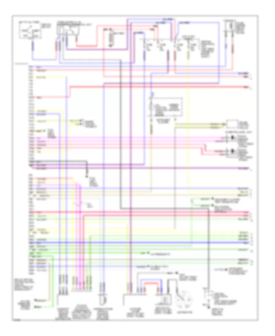
2.3L Turbo, Engine Performance Wiring Diagrams (2 of 2) for Volvo 850 GLT 1997
List of elements for 2.3L Turbo, Engine Performance Wiring Diagrams (2 of 2) for Volvo 850 GLT 1997:
- (on center console, forward of shift lever)
- A/c pressure sensor (front center of eng compt)
- A/c system (a/c pressostat & a/c relay w/ ecc)
- A/c system (a/c solenoid sw)
- A/c system (ecc control module)
- A/c system (w/ ecc) (a/c relay)
- A/t
- A10
- A11
- A18
- A26
- Acc
- Accelerometer
- Aw 50-42 automatic transmission control module (right front fender, in control module box)
- B10
- B11
- B12
- B13
- B14
- B15
- B16
- B17
- B18
- B19
- B20
- B21
- B22
- B23
- B24
- B25
- B26
- B27
- B28
- B29
- B30
- B31
- B32
- B33
- B34
- B35
- B36
- B37
- B38
- B39
- B40
- B41
- B42
- B43
- Central electrical unit (left rear corner of engine compt)
- Cruise control module (in central elec unit)
- Di power stage
- Distributor
- Eng temp gauge input
- Fuel pump (in fuel tank)
- Fuel pump relay (in central electrical unit)
- Fuse #2 15a
- G102 (left front shock tower)
- G303 (on right rear cross- member)
- G901 (top right side of steering column)
- Hot at all times
- Igniti0n coil
- Ignition switch
- Input trip computer
- Instrument cluster
- M/t
- Mal- function indicator "check engine"
- Module box)
- Motronic 4.3 engine control module (right front fender, in control
- Nca
- Off
- On-board diagnostics socket
- Overload relay 15+ (in central electrical unit)
- Pnk
- Red
- Run
- Start
- Tach input
- Turbo control valve (near left rear of engine)
- Vehicle speed output
2.4L
2.4L, Engine Performance Wiring Diagrams (1 of 2) for Volvo 850 GLT 1997
List of elements for 2.4L, Engine Performance Wiring Diagrams (1 of 2) for Volvo 850 GLT 1997:
- (in central elec. unit)
- A/c high pressure sensor (w/ ecc)
- A/c pressostat
- A/c relay pin 4 (w/ ecc)
- A/t only
- A10
- A11
- A12
- A13
- A14
- A15
- A16
- A17
- A18
- A19
- A20
- A21
- A22
- A23
- A24
- A25
- A26
- A27
- A28
- A29
- A30
- Acc
- Aw 50-42 automatic transmission control module (right front of engine compt.)
- B10
- B11
- B12
- B13
- B14
- B15
- B16
- B17
- B18
- B19
- B20
- B21
- B22
- B23
- B24
- B25
- B26
- B27
- B28
- B29
- B30
- Battery
- Camshaft position sensor (behind distributor)
- Central electrical unit (left rear corner of engine compt.)
- Cruise control module
- Di power stage (front of left strut tower)
- Distributor
- Ecc control module pin a23 (optional)
- Engine cooling fan relay
- Ezk (di) ignition system control module (right front of engine compt.)
- Fuse #1 15a
- Fuse #2 15a
- Fuse #33 15a
- Fuse #8 40a
- G102 (on left front shock tower)
- G119 (left front of eng)
- Hot at all times
- Hot in acc or run
- Igniti0n coil (front of left strut tower)
- Ignition switch
- Instrument cluster
- Instrument cluster pin a11 (tachometer)
- Instrument cluster temp. gauge pin a26
- Knock sensor (front) (right front of eng)
- Knock sensor (rear) (left front of eng)
- Mal- function indicator "check engine"
- Nca
- Off
- Overload relay 15+ (in central electrical unit)
- Pnk
- Pulse sensor (below distri- butor)
- Red
- Run
- Speedo- meter (output)
- Start
- Variable intake manifold solenoid (left side of engine)
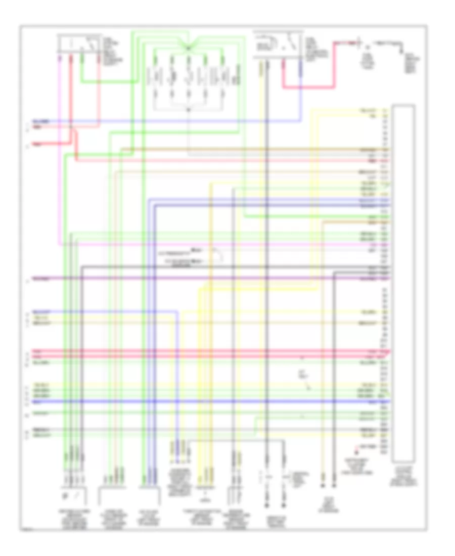
2.4L, Engine Performance Wiring Diagrams (2 of 2) for Volvo 850 GLT 1997
List of elements for 2.4L, Engine Performance Wiring Diagrams (2 of 2) for Volvo 850 GLT 1997:
- A/c pressostat
- A/c solenoid coupling
- A/t only
- A10
- A11
- A12
- A13
- A14
- A15
- A16
- A17
- A18
- A19
- A20
- A21
- A22
- A23
- A24
- A25
- A26
- A27
- A28
- A29
- A30
- B10
- B11
- B12
- B13
- B14
- B15
- B16
- B17
- B18
- B19
- B20
- B21
- B22
- B23
- B24
- B25
- B26
- B27
- B28
- B29
- B30
- Central elec- trical unit
- Engine temperature sensor (right front of engine)
- Fuel injectors
- Fuel pump (in fuel tank)
- Fuel pump relay (in central electrical unit)
- Fuel system main relay (front of engine compt.)
- G119 (left front of engine)
- G310 (behind right rear seat)
- Heated oxygen sensor (on exhaust pipe, before converter)
- Iac idling valve (left front of engine)
- Instrument cluster pin a9 (trip computer)
- Lh 3.2 mfi control module (right front of eng compt)
- Mass air flow sensor (front of air cleaner housing)
- On-board diagnostic socket a (partial) (right front corner of eng compt)
- Pnk
- Red
- Solid state
- Throttle position sensor (left front of engine)